
 ?Mathematical formulae have been encoded as MathML and are displayed in this HTML version using MathJax in order to improve their display. Uncheck the box to turn MathJax off. This feature requires Javascript. Click on a formula to zoom.
ABSTRACT
Among reinforcement methods for 3D concrete printing (3DCP) structures, steel cable reinforcement and reinforced concrete confined by 3DCP formwork (RC-3DPF) methods offer high design freedom and automation. However, the former lacks reinforcement in directions perpendicular to the printing direction, and the latter cannot satisfy constructional requirements. This paper proposed a hybrid approach: the steel rebar reinforced concrete column confined by the steel cable reinforced 3DCP permanent formwork (RC-SC-3DPF). Axial compression tests and theoretical analysis were conducted to study axial performances. Test results showed steel cables and fibres added to 3DCP formwork benefit RC-SC-3DPF structural performances. With a steel cable confinement ratio above 0.534%, RC-SC-3DPF outperforms the traditional case. Steel fibre, compared to PVA fibre, demonstrates greater potential for RC-SC-3DPF due to improved axial load resistance and reduced ductility loss. A theoretical model, based on experimental results, existing standards, and M&T model, was developed to effectively evaluate RC-SC-3DPF structural behaviour.
1. Introduction
In the past few years, 3D printing technology has been paid more attention to in the fields of building and construction owing to the advantages of high design freedom and automation [Citation1–7]. However, the current biggest challenge is to guarantee that 3D concrete printing (3DCP) structural members combining reinforcement can satisfy the requirements of traditional construction [Citation8]. Consequently, a series of investigations have been conducted to determine an effective approach to insert reinforcement into 3DCP structural members.
According to the printing process arrangement, reinforcement addition methods can be categorised as pre-installed reinforcement methods, in-process reinforcement methods, and post-installed reinforcement methods, respectively [Citation9], which are detailed as follows:
| (i) | Pre-installed reinforcement methods: Reinforcement is installed before 3D printing. Hack and Lauer [Citation10] explored a solution for extruding concrete on the pre-printed metal mesh. However, it is difficult to obtain feasible 3DCP materials for this method. Materials with a low yield stress cannot be constrained by mesh formworks, while materials with a high yield stress tend to cause a poor bond with 3D printing mesh. Another method is double-side extrusion on the prefabricated steel cage, which has been accepted by several industry companies [Citation11,Citation12]. However, the bonding between steel cages and 3DCP members is prone to be poor since steel rebars with a considerable diameter were arranged at interfaces [Citation13]. | ||||
| (ii) | In-process reinforcement methods: Reinforcement is installed together with 3D printing. Based on the studies of [Citation14–16], steel cables can be extruded together with 3DCP cementitious materials and benefit the flexural performances of 3DCP beams. Although the bonding between steel cable and 3D printing concrete is weaker than the bonding between steel cable and cast concrete [Citation14], this problem is not critical due to the sufficient anchorage length. Gebhard et al. [Citation17] confirmed that steel cable positioning at interlayers is also effective in improving the flexural behaviour of 3DCP beams. However, it is worth noting that since steel cables follow the printing direction (PDir), they provide limited reinforcement for the directions perpendicular to PDir. | ||||
| (iii) | Post-installed reinforcement methods: Reinforcement is installed after 3D printing. Marchment et al. [Citation18] proposed an approach of penetrating steel rebars into 3DCP structural members. Although a tube was designed to guide the penetration direction, the pull-out test results indicated that the bonding between the steel rebar and the 3DCP structural member is extremely poor in the upper layers. Another widely used post-installed reinforcement method is to separate reinforcement and 3DCP structural members. The studies of [Citation19,Citation20] introduced a reinforcement method of using unbonded post-tensioning tendons; however, with no transverse reinforcement, the corresponding test results showed that the 3DCP structures had brittle failure modes. Gebhard et al. [Citation17] reported that the structural ductility can be improved by replacing the unbonded post-tensioning tendon with the bonded reinforcement. Accordingly, the revised system can be regarded as reinforced concrete confined by 3DCP permanent formwork (RC-3DPF). Owing to no conflict between reinforcement installation and the printing process, RC-3DPF allows the highest design freedom among all methods. Furthermore, as developed by Du et al. [Citation21] and Teng et al. [Citation22], the automation of realising RC-3DPF can be significantly improved by integrating Building Information Modelling and 3D concrete printers with robotic arms. However, as reported by [Citation23,Citation24], the load resistance of RC-3DPF is significantly lower than that of the traditional case without 3DCP formwork, and the peeling failure of 3DCP formwork could be observed during tests, which can be caused by the poor bond between inner cast concrete and hardened 3D printing concrete [Citation24,Citation25]. | ||||
To summarise, among methods of combining reinforcement and 3DCP structural members, the RC-3DPF and steel cable reinforcement methods have better potential due to high design freedom and automation; however, the load resistance of RC-3DPF does not meet the requirements of traditional construction, and steel cables provide limited reinforcement for the directions perpendicular to PDir.
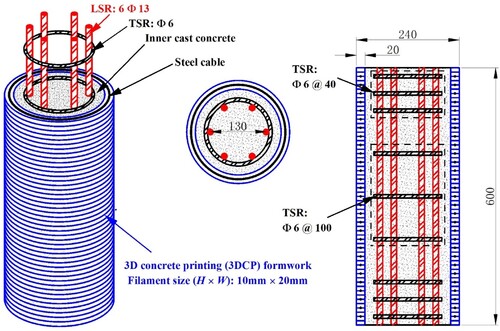
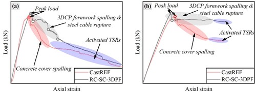
In this paper, a new approach combining the RC-3DPF method and the steel cable reinforcement method is proposed and studied in the column case, which is the steel rebar reinforced concrete column confined by the steel cable reinforced 3DCP permanent formwork (RC-SC-3DPF). As shown in , in RC-SC-3DPF, steel cables inserted into 3DCP formwork were applied to provide confinement for longitudinal steel rebars (LSRs), concrete core, and bonding between 3DCP formwork and inner cast concrete, while LSRs embedded into inner cast concrete replenish the reinforcement in the directions perpendicular to PDir, which the steel cable reinforcement method lacks. To further study the structural performances of RC-SC-3DPF, axial compression tests and theoretical analysis were conducted accordingly.
Figure 1. Concept figure of the steel rebar reinforced column confined by the steel cable reinforced 3DCP permanent formwork (RC-SC-3DPF). (TSR and LSR correspond to transverse steel rebar and longitudinal steel rebar).
2. Experimental programmes
2.1. Fabrication of RC-SC-3DPF
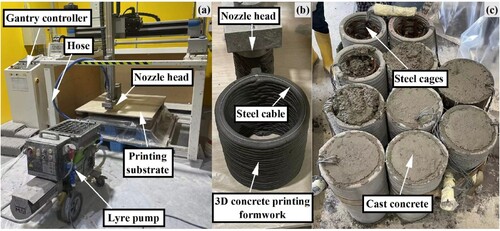
The fabrication of RC-SC-3DPF consists of three steps. Firstly, as shown in (a,b), a printing system including an MAI Lyre pump, a 25.4 mm diameter hose, and a nozzle head was applied to print the 3DCP formwork. The formwork filaments were set as 20 mm in width and 10 mm in height, and steel cables were designed to be inserted at interlayers. The layered printing time gap was set as 1 min for adding the steel cable on the interlayer surface. After 3D printing, the hardened formworks were cured in the laboratory at 22°C temperature and 59% relative humidity for over 30 days. Secondly, the steel cages containing 13 mm-diameter ribbed LSRs and 6 mm-diameter transverse steel rebars (TSRs) without ribs were positioned at the centre of the column. The spacing of TSRs was set as 40 mm in the areas near the boundaries to avoid boundary failure, while in the areas far from the boundaries, the spacing was set as 100 mm. Finally, as shown in (c), fresh concrete was infilled into the 3DCP formwork. A construction vibrator was applied to compact the cast concrete, and the specimens were continuously air-cured for over 30 days till experiments.
Figure 2. (a) The applied 3D printing system; (b) Printing process of the steel cable reinforced 3DCP formwork; (c) Infilled cast concrete in the 3DCP formwork.
2.2. Case and parametric designs
shows case and parametric designs in this study. In detail, Case No.1 and Case No.2 correspond to the reference case of the traditional steel rebar reinforced concrete column without 3DCP formwork (CastREF) and the reference case of the steel rebar reinforced column confined by 3DCP formwork without steel cables (3DPREF). Since TSRs confine concrete core and restrict LSR buckling, the TSR diameter and spacing significantly affect the structural performances of CastREF [Citation26]. Correspondingly, Cases No.3-6 (3DP-4L, 3DP-2L, 3DP-1L, and 3DP-1.5D) were designed to study the effects of the steel cable diameter and spacing on the axial performances of RC-SC-3DPF. The confinement ratio (Cf) was used to quantify the confinement effects provided by steel cables, which is expressed as [Citation27]:
(1)
(1) where ρs is the volumetric ratio of steel cables to the concrete core confined by steel cables, while Dsc (mm) and Ssc (mm) are the diameter of the concrete core confined by steel cables and the spacing of steel cables. Additionally, polyvinyl alcohol (PVA) and steel fibre are widely used to improve the mechanical properties of 3D printing concrete [Citation28–32]; thus, Cases No.7-9 (3DP-2L-0.5PF, 3DP-2L-1.0PF, and 3DP-2L-0.5SF) were designed to study the effects of the fibre type and the fibre content on the structural performances of RC-SC-3DPF. The PVA fibre is 40 µm in diameter and 8 mm in length, and steel fibre is 0.2 mm in diameter and 3 mm in length.
Table 1. Details of designed cases.
2.3. Material compositions and properties
In this study, the applied materials include cast concrete, 3D printing concrete, LSR, TSR, and steel cable. As shown in , the composition of the cast concrete contains Ordinary Portland Cement (OPC) (Portland Cement, ASIA CEMENT Pte. Ltd.), sand (Particle size ≤ 2 mm), coarse aggregate (Particle size ≤ 10 mm), silica fume (Microsilica Grade 940, Elkem), superplasticizer (ADVA 181 N, Grace Pte. Ltd.) and water, while the 3D printing concrete composition includes premix cement (Portland composite cement, LAFARGE PHOENIX), sand (Particle size ≤ 2 mm), silica fume (Microsilica Grade 940, Elkem), and water, which follows the studies of [Citation1,Citation2,Citation6].
Table 2. Material composition of cast concrete and 3D printing concrete.
Based on ASTM C39 [Citation33], uniaxial compression tests were conducted with a loading rate of 0.5 mm/min to obtain the material properties of the cast concrete and the 3D printing concrete. According to ASTM E8 [Citation34], tension coupon tests were carried out with a loading rate of 1.0 mm/min to determine the material properties of LSR and TSR. The corresponding material properties are detailed in .
Table 3. Material properties.
2.4. Test setup
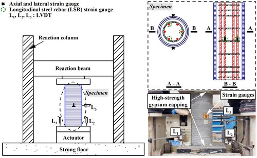
As shown in , a 5000kN servo-hydraulic-controlled machine was applied to test the axial compressive performances of the specimens. The loading rate was set as 0.18 mm/min under the displacement control. Before experiments, two linear variable differential transformers (LVDTs), L1 and L2, were installed to measure the axial deformation of the specimen, and one LVDT, L3, was set to obtain the lateral deformation of the specimen. Furthermore, four strain gauges were attached to the surface of the specimen to determine the axial and lateral strain development, and three strain gauges were attached to the LSRs to measure the corresponding strain development. Additionally, to guarantee specimen levelling and uniform load distribution, high-strength gypsum was cast on the top and bottom surfaces of the specimens. For each case, the experiment was set ended till the axial load (N) dropped to approximately 25% of the peak load (Np).
Figure 3. Test setup of column specimens.
3. Experimental results and discussions
In this study, the axial strain – load diagram and the strain ductility were determined to describe the structural performances. For tested specimens, when the axial load (N) is lower than the peak load (Np), the axial strain was recorded from the strain gauges on the specimen surface to accurately measure the elastic behaviour, while in the post-peak stage, due to specimen surface cracks fracturing strain gauges, the axial strain was obtained from LVDTs. For the LSRs, the axial strain was determined from the attached strain gauges. On the other hand, the ratio of the strain (ϵ50) at 50% of Np in the post-peak stage to the strain (ϵp) at Np is used to describe the strain ductility (μ) of the tested specimen [Citation27], which is expressed as:
(2)
(2) summarises the test results of Np, ϵp, ϵ50, and μ, respectively, with the detailed structural behaviour shown from , , .
Table 4. Summary of experimental results.
3.1. Failure modes
The failure modes of the tested specimens are presented in . It is evident that CastREF, 3DPREF, and RC-SC-3DPF possess different failure modes. For the failure mode of CastREF shown in (a,d), the failure was initiated at hairline cracks that propagated along the axial direction. As the axial strain increased, the spalling of the concrete cover appeared, followed by the LSR buckling, which is consistent with the typical failure mode of the traditional reinforced concrete column, according to the experimental results determined by the studies of [Citation27,Citation35,Citation36]. (b,e) show that Prior to Np, the 3DPREF surface did not show major cracks, while when N = Np, major cracks appeared suddenly with 3DCP formwork immediately peeling and spalling, which fits the results observed by Chen et al. [Citation24]. Afterward, as the axial strain increased, major cracks appeared on the surface of the inner cast concrete, followed by the LSR buckling, which is similar to the failure mode of CastREF after the concrete cover spalled. For the failure mode of RC-SC-3DPF shown in (c,f–l), at the stage of N = 0.95–1.0 Np, the rupture of steel cables and hairline cracks could be observed at the middle positions of specimens. As axial strain increased, the rupture of steel cables developed from the middle positions to the boundary positions of specimens. The steel cable rupture confirms that the anchorage length of steel cables is long enough to provide a sufficient bond between steel cables and interlayers; therefore, steel cables at interlayers have the potential to effectively improve the mechanical performances of 3DCP formwork as the study of Gebhard et al. [Citation17]. In the post-peak stage of RC-SC-3DPF, the crack along the interlayer (CAI) could also be observed, which can be caused by the existing crack tips at the notch of the interlayer [Citation37], and as the axial strain rose, major cracks developed along the rupture positions of steel cables, which resulted in the debonding and spalling of the 3DCP formwork. Although the inner cast concrete cannot be observed due to the obstruction of the 3DCP formwork, it can be predicted that with the 3DCP formwork debonding and spalling, the failure mode of the inner cast concrete tends to be similar to that of 3DPREF after the 3DCP formwork peeled away.
Figure 4. Failure modes of specimens: (a) CastREF at Np; (b) 3DPREF at Np; (c) typical RC-SC-3DPF at Np; (d) CastREF at failure; (e) 3DPREF at failure (f) 3DP-4L at failure; (g) 3DP-2L at failure; (h) 3DP-1L at failure; (i) 3DP-1.5D at failure; (j) 3DP-2L-0.5PF at failure; (k) 3DP-2L-1.0PF at failure; (l) 3DP-2L-0.5SF at failure. (CAI is the crack along the interlayer)
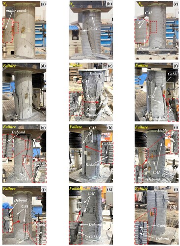
Moreover, (f–i) show that as the steel cable Cf rises, an increasing number of major cracks can be observed on the specimen surface, and the peeling failure of the 3DCP formwork is restricted, indicating that the increase in steel cables makes the failure modes of RC-SC-3DPF close to that of CastREF. It can also be observed that 3DP-1L and 3DP-1.5D have more CAIs compared to 3DPREF, 3DP-2L, and 3DP-4L, which can be attributed to the effects of the diameter of the steel cable and the number of major cracks. On the one hand, the larger diameter of steel cables negatively affects the interlayer bond property [Citation13], which may result in the initiation of CAIs. On the other hand, a larger number of major cracks causes a reduction of the distance between adjacent cracks, which further reduces the total fracture energy of the propagation of CAIs [Citation38]. Additionally, (j–l) show that 3DP-2L-0.5PF and 3DP-2L-1.0PF have similar failure modes to 3DP-1L and 3DP-1.5D, while the failure mode of 3DP-2L-0.5SF is close to that of 3DP-2L, suggesting that compared to steel fibre, PVA fibre is more effective in restricting crack propagation and leads to a more uniform distribution for cracks.
3.2. Axial strain – load diagram
shows typical axial strain – load diagrams of tested specimens and LSRs. For CastREF, the axial strain – load curve in the stage of N < Np is nearly linearly elastic. In the post-peak stage, a rapid decrease in the axial load can be first seen for the specimen and LSR, which can correspond to the process of major crack propagation and concrete cover spalling [Citation39]. Afterward, with TSRs activated, the concrete core and LSRs resist the applied load till LSRs buckle and the concrete core crushes, which leads to a gentle descending curve in the post-peak stage [Citation40]. For RC-SC-3DPF, the axial strain – load diagram of the N < Np stage also tends to be linearly elastic. After N = Np, a step-mode descending curve can be observed for the specimen, which can correspond to the process of steel cable rupturing and 3DCP formwork debonding from the inner cast concrete. On the other hand, for the strain – load curve of LSRs in the post-peak stage, as the axial strain rises, a plateau of load resistance can be observed after a small axial load loss, revealing that steel cables may benefit the confinement of LSRs and the concrete core. After the process of steel cable rupturing and 3DCP formwork spalling, TSRs are activated. At this stage, LSRs and the concrete core provide resistance for the applied load till LSRs buckle and the concrete core crushes, which results in a gentle descending curve that is similar to the behaviour of CastREF after the spalling of the concrete cover.
Figure 5. Typical axial strain – load diagram: (a) Tested specimens; (b) Longitudinal steel rebars (LSRs).
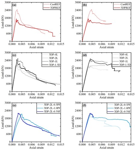
The effects of steel cable Cf, fibre type, and fibre content on the axial strain – load diagrams are detailed in . Firstly, (a,b) present that Np of 3DPREF is 1750.2kN that is 71% of CastREF, which confirms that the axial peak load resistance of RC-3DPF is significantly lower than that of the traditional steel rebar reinforced column [Citation23,Citation24]. By combining with failure modes shown in (b), it can be revealed that the low peak load resistance of RC-3DPF can be attributed to the confinement loss caused by the sudden failure of 3DCP formwork peeling and spalling. As studied by [Citation24,Citation25], the sudden peeling and spalling failure of 3DCP formwork results from the poor bond between 3DCP formwork and inner cast concrete. Afterward, TSRs are immediately activated with the concrete core and LSRs resisting the axial load; thus, the gentle descending strain – load relationship can be observed in the post-peak stage of 3DPREF and LSRs. Secondly, (c,d) show that as the steel cable Cf increases from 0.084% to 0.671%, Np of 3DP-4L, 3DP-2L, 3DP-1.5D, and 3DP-1L are 2024.9kN, 2073.0kN, 2469.0kN, and 2553.4kN, respectively, which are 15.7%, 18.4%, 41.1%, and 45.9% higher than that of 3DPREF. By combining with the failure modes shown in (e–i), it can be found that the steel cable reinforcement benefits Np by restricting major crack propagation and limiting the appearance of 3DCP formwork peeling. Furthermore, Np of 3DP-1.5D and 3DP-1L are 0.5% and 3.7% higher than that of CastREF, indicating that with the steel cable Cf larger than 0.534%, RC-SC-3DPF may have a larger axial peak load resistance compared to CastREF. Finally, (e,f) present that Np of 3DP-2L-0.5PF, 3DP-2L-1.0PF, and 3DP-2L-0.5SF are 2078.3kN, 2156.0kN, and 2209.0kN, respectively. which are 2.6%, 4.0%, and 6.6% higher than 3DP-2L. These trends suggest that the positive effects of PVA fibre on the axial peak load resistance of RC-SC-3DPF are not as good as those of steel fibre, which can be attributed to the effects of different fibre types on the mechanical properties of 3D printing concrete. As studied by [Citation29,Citation41,Citation42], steel fibre significantly benefits the tensile strength of 3D printing concrete, while the main effect of PVA fibre is to enhance the ultimate tensile strain of 3D printing concrete instead of the tensile strength. Piscesa et al. [Citation43] revealed that the effects of fibre on the axial load resistance of columns are ascribed to fibre strengthening the tensile strength of concrete cover and further restricting concrete cover spalling. Consequently, compared to PVA fibre, steel fibre is more effective in improving the axial load resistance of RC-SC-3DPF.
Figure 6. Axial strain – load diagrams: (a) Effects of 3DCP formwork on strain – load curve of specimens; (b) Effects of 3DCP formwork on strain – load curve of LSRs; (c) Effects of steel cable Cf on strain – load curve of specimens; (d) Effects of steel cable Cf on strain – load curve of LSRs; (e) Effects of fibre type and content on strain – load curve of specimens; (f) Effects of fibre type and content on strain – load curve of LSRs. (LSR corresponds to longitudinal steel rebar, and Cf is the confinement ratio)
3.3. Axial strain ductility
The axial strain ductility (μ) results are shown in . Firstly, it presents that μ of 3DPREF is significantly higher than that of CastREF, which can be attributed to the sudden peeling and spalling failure of 3DCP formwork. As discussed in Section 3.2, in the post-peak stage, the structural behaviour of CastREF after the concrete cover spalls is more ductile than that in the process of the concrete cover spalling, while the structural behaviour of 3DPREF in the post-peak stage is close to that of CastREF after the concrete cover spalls due to the 3DCP formwork sudden peeling and spalling failure causing TSR immediately activated, which explains that 3DPREF has a higher μ value compared with CastREF. Secondly, it can be observed that as the steel cable Cf increases, μ values of RC-SC-3DPF have a decreasing tendency, which can be attributed to steel cables restricting the 3DCP formwork peeling and spalling. As shown in , with the increase of steel cables providing more confinement for RC-SC-3DPF, the sudden peeling failure of the 3DCP formwork is converted to a process of 3DCP formwork peeling and spalling. In this process, TSRs have not been activated, and the axial load is resisted by the whole RC-SC-3DPF; thus, the corresponding structural behaviour is less ductile than that after 3DCP formwork peels and spalls, which explains the increasing steel cable Cf negatively affects μ of RC-SC-3DPF. Thirdly, it is evident that compared with CastREF, 3DP-1.5D possesses larger Np and μ values, while 3DP-1L has a larger Np value and a similar μ value, which indicates that when steel cable Cf is larger than 0.534%, RC-SC-3DPF may have similar and even better structural performances than the CastREF. Finally, shows that the μ value of 3DP-2L-0.5SF is larger than those of 3DP-2L-0.5PF and 3DP-2L-1.0PF and as the PVA fibre content rises, μ values have a decreasing trend, which can be caused by fibre affecting the specimen stiffness. As studied by [Citation44,Citation45], plastic fibre negatively affects concrete elastic modulus, while steel fibre benefits concrete elastic modulus, which fits the stiffness trend of RC-SC-3DPF, as shown in (e). Hence, an ϵp sequence of 3DP-2L-0.5SF < 3DP-2L-0.5PF < 3DP-L-1.0PF was determined, which leads to the μ sequence of 3DP-2L-0.5SF > 3DP-2L-0.5PF > 3DP-2L-1.0PF.
3.4. Parametric studies
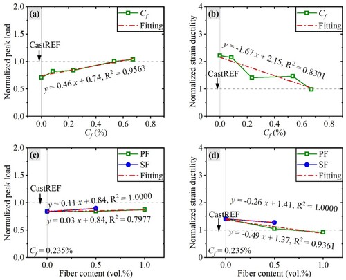
To compare the axial performances of CastREF, 3DPREF, and RC-SC-3DPF, the normalised peak load was defined as the Np ratio of the tested specimen and CastREF, and the normalised strain ductility was defined as the μ ratio of the tested specimen and CastREF. The effects of steel cable Cf, fibre type, and fibre content on normalised peak load and normalised strain ductility are summarised in .
Figure 7. (a) Effects of steel cable Cf on the normalised peak load; (b) Effects of steel cable Cf on the normalised strain ductility; (c) Effects of fibre content and type on the normalised peak load; (d) Effects of fibre content and type on the normalised strain ductility. (PF and SF correspond to polyvinyl alcohol fibre and steel fibre, and Cf is the confinement ratio)
3.4.1. Effects of steel cable confinement ratio (Cf)
(a) presents that as the steel cable Cf increases from 0 to 0.671%, the normalised peak load of RC-SC-3DPF tends to increase from 0.71 to 1.04 linearly. On the other hand, (b) shows that the relationship between the steel cable Cf and the normalised strain ductility can be roughly described by a descending straight line that begins from 2.22 to 0.98. Consequently, it can be revealed that when the steel cable Cf is less than 0.534%, the increase in the steel cable Cf makes the structural performances of RC-SC-3DPF closer to those of CastREF, suggesting that steel cable reinforcement can confine the poor bond between the 3DCP formwork and inner cast concrete and make the 3DCP formwork and inner cast concrete act as a CastREF-like unit to together resist the axial load. Moreover, when the steel cable Cf is larger than 0.534%, the increase in steel cables Cf further benefits the axial peak load resistance and makes Np values even surpass that of CastREF, which indicates that steel cable reinforcement can provide confinement for the LSRs and the concrete core, which is similar to the effects of the TSRs.
3.4.2. Effects of fibre content and type
As shown in (c), PVA and steel fibre in 3DCP formwork benefit the normalised peak load, and the positive effect of steel fibre is more significant than that of PVA fibre. As steel fibre vol.% increases from 0 to 0.5%, the normalised peak load increases from 0.84 to 0.90, while as PVA fibre vol.% increases from 0 to 1.0%, the normalised peak load roughly linearly increases from 0.84 to 0.88. As shown in (d), PVA and steel fibre in 3DCP formwork negatively affect the normalised strain ductility of RC-SC-3DPF, and the negative effect of PVA fibre is more significant than those of steel fibre. As steel fibre vol% increases from 0 to 0.5%, the normalised strain ductility decreases from 1.41 to 1.28, while as PVA fibre vol% increases from 0 to 1.0%, the normalised strain ductility shows a roughly linearly descending trend from 1.28 to 0.92. Hence, it can be revealed that PVA fibre and steel fibre make the structural performances of RC-SC-3DPF similar to those of CastREF. Because PVA fibre and steel fibre were only added to the 3DCP formwork, the effects of PVA fibre and steel fibre are to confine the poor bond between the 3DCP formwork and inner cast concrete and make the 3DCP formwork and inner cast concrete perform as a CastREF-like unit to resist the axial load, which are similar to the effects of steel cable as stated in Section 3.4.1. Additionally, it can be found that compared to PVA fibre, steel fibre has more potential to be applied to RC-SC-3DPF since it is more effective in improving the normalised peak load with fewer negative effects on normalised strain ductility.
4. Theoretical analysis
The existing standards were applied to predict the Np of tested specimens, which aims to study the feasibility of existing standards in evaluating the corresponding structural behaviour. Moreover, a theoretical axial strain – load model was proposed based on the experimental results and existing models for confined concrete to evaluate the structural behaviour of RC-SC-3DPF.
4.1. Comparison with existing standards
Based on BS EN-1994-1-1 (EC-4, 2004) [Citation46], the axial peak load resistance of RC-SC-3DPF can be evaluated by:
(3)
(3) where NEC4 (MPa) is the axial peak load resistance from the evaluation of EC-4. fy (MPa), fc,3DCP (MPa), and fc,cast (MPa) are the yield strength of LSR, the compressive strength of 3D printing concrete, and the compressive strength of the cast concrete, respectively. As (mm2), Ac,3DCP (mm2), and Ac, cast (mm2) are the cross-section areas of LSRs, 3DCP formwork, and inner cast concrete. A reduction factor of 0.85 was applied by EC-4 to consider the effects of concrete spalling on load resistance [Citation45].
According to ACI-318-19 [Citation47], the axial peak load resistance of RC-SC-3DPF can be predicted by:
(4)
(4) where NACI (MPa) is the axial peak load resistance from the prediction of ACI-318-19. Compared with EC-4, another reduction of 0.85 was used by ACI-318-19 to account for accidental eccentricity [Citation45].
Based on AISC-LRFD-2010 [Citation48], the axial peak load resistance of RC-SC-3DPF can be evaluated by:
(5)
(5) where NAISC (MPa) is the axial peak load resistance from the evaluation of AISC-LRFD-2010. Compared with EC-4, AISC-LRFD-2010 did not consider the negative effects of concrete spalling on axial load resistance. Instead, AISC-LRFD-2010 applied a reduction factor of 0.95 to account for the negative effects of incompatible deformation between concrete and steel [Citation49].
According to material properties shown in and experimental results shown in , the ratio of the peak load from axial compression tests to the axial peak load resistance from standard prediction was determined to describe the feasibility of EC-4, ACI-318-19, and AISC-LRFD-2010 in evaluating the axial peak load resistance of tested specimens, which is shown in . It is evident that EC-4 provides the most reasonable prediction on the Np of CastREF with an error of approximately 2%. ACI-318-19 highly underestimates the Np of CastREF, which can be attributed to no eccentricity during tests. AISC-LRFD-2010 provides CastREF with unsafe prediction, which may be attributed to the negative effects of concrete spalling being more significant than those of incompatible deformation between concrete and steel. Thus, a reduction factor of 0.85 is reasonable to be applied to evaluate the load resistance of reinforced columns. Furthermore, shows that EC-4 possesses good prediction on the Np of 3DP-1L and 3DP-1.5D; however, it significantly overestimates the Np of 3DPREF and remaining RC-SC-3DPF cases. It is because EC-4 does not consider the effects of the steel cable Cf, fibre content, and fibre type on the Np of RC-SC-3DPF. Consequently, it is not feasible to apply existing standards to evaluate the axial peak load resistance of RC-SC-3DPF directly. Instead, the structural performances of RC-SC-3DPF require to be further investigated based on theoretical analysis, which is detailed in Section 4.2.
Table 5. Comparison between experimental results and standard prediction results.
4.2. Axial strain – load model prediction
To further evaluate the structural performances of RC-SC-3DPF, an axial strain – load model was investigated. According to Mander et al. [Citation26], the strain – stress relationship of confined concrete can be described as:
(6)
(6)
(7)
(7)
(8)
(8)
(9)
(9)
(10)
(10)
(11)
(11)
(12)
(12) where fc (MPa) and ϵc are the axial stress and the axial strain of concrete, fcc’ (MPa) and fco’ (MPa) are the compressive strengths of confined and unconfined concrete, ϵcc and ϵco are the strains at the compressive strength for confined and unconfined concrete, Ec (MPa) and Esec (MPa) are the elastic modulus and the secant modulus of confined concrete, and fi’ (MPa) is the confinement pressure.
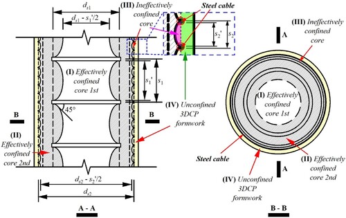
shows that a typical RC-SC-3DPF consists of four parts under different stress states: the 1st effectively confined core which is confined by TSRs and steel cables, the 2nd effectively confined core which is confined by steel cables, the ineffectively confined core due to the arching action of steel cables, and the unconfined 3DCP formwork, respectively; thus, the stress – strain relationship of each part requires to be analyzed individually. It is worth noting that because the proportion of 3D printing concrete in the 2nd effectively confined core can be negligible, the 2nd effectively confined core is assumed to be filled by the inner cast concrete. Based on Teng et al. [Citation50], the stress – strain relationship of concrete in each part of RC-SC-3DPF can be calculated by:
(13)
(13)
(14)
(14)
(15)
(15)
(16)
(16)
(17)
(17)
(18)
(18)
(19)
(19) where ke1 and ke2 are confinement effectiveness coefficients of TSR and steel cable. s1 (mm) and s1’ (mm) are the clear vertical spacing and the centre-to-centre vertical spacing of TSRs, while s2 (mm) and s2’ (mm) are the clear vertical spacing and the centre-to-centre vertical spacing of steel cables. ds1 (mm) and ds2 (mm) represent the TSR spiral diameter between bar centres and the steel cable spiral diameter between steel cable centres. Es1 (GPa) and Es2 (GPa) are the elastic moduli of TSR and steel cable. ρsc-s corresponds to the confining stiffness ratio of TSR to steel cable. fy,s′ (MPa) and fy,sc′ (MPa) are the yield strengths of TSR and steel cable. fco,cast′ (MPa), fcc,I′ (MPa), and fcc,II′ (MPa) are the compressive strengths of unconfined cast concrete, confined cast concrete in the 1st effectively confined core, and confined cast concrete in the 2nd effectively confined core, respectively. Moreover, the axial strain – load relationship of RC-SC-3DPF can be determined as:
(20)
(20)
(21)
(21)
(22)
(22)
(23)
(23) where f3DCP (MPa), fI (MPa), and fII (MPa) are the compressive stresses of unconfined 3DCP formwork, confined cast concrete in the 1st effectively confined core, and confined cast concrete in the 2nd effectively confined core, respectively, which can be determined from Eq.(6). σy,L (MPa) is the compressive stress of LSR, which follows the strain – stress relationship determined by the tension coupon tests in Section 2.3. AI (mm2), AII (mm2), and Aco (mm2) are the cross-section areas of the 1st effectively confined core, the 2nd effectively confined core, and the unconfined 3DCP formwork, respectively. Atot (mm2) and ALSR (mm2) represent the total cross-section areas of the column and LSRs. N (N) is the axial load. Since the derived strain – load relationship is based on Mander et al. [Citation26] and Teng et al. [Citation50], it is called M&T model in this study.
Figure 8. Different parts in the steel rebar reinforced concrete column confined by the steel cable reinforced 3D concrete printing permanent formwork (RC-SC-3DPF).
shows the comparison between the test results and the prediction results from the M&T model. It is evident that the M&T model significantly overestimates the axial load resistance of the specimens, which can be attributed to the M&T model not considering the negative effects of 3DCP formwork debonding and spalling, as discussed in Section 4.1. Thus, a reduction factor (Rf1) of 0.85 is considered accordingly [Citation45]. Furthermore, as shown in (a,c), the normalised peak load of RC-SC-3DPF tends to be linearly dependent on the steel cable Cf and fibre content. Therefore, a coefficient (Rf2) considering steel cable Cf, fibre type, and fibre content is proposed as:
(24)
(24) where VSF and VPF are the contents of steel fibre and PVA fibre. In addition, as shown in (b,d), the normalised strain ductility of RC-SC-3DPF is roughly linearly related to the steel cable Cf and fibre content. Thus, a coefficient (Rf3) is proposed with the expression as:
(25)
(25) Accordingly, the strain (ϵ3DP) and load (N3DP) relationship of RC-SC-3DPF can be expressed as:
(26)
(26)
(27)
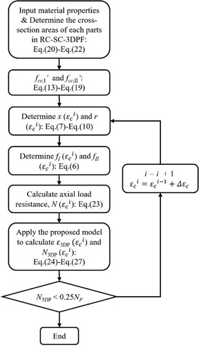
(27) presents that the proposed model has relatively good predictions for the structural performances of RC-SC-3DPF, which proves the feasibility of the proposed model (from Eq.(24) to Eq.(27)) in evaluating the axial performances of RC-SC-3DPF. Accordingly, the strain – load relationship of RC-SC-3DPF can be determined by following the flow chart in .
Figure 9. Results comparison determined from the M&T model, the proposed model, and axial compression tests: (a) CastREF; (b) 3DPREF; (c) 3DP-4L; (d) 3DP-2L; (e) 3DP-1L; (f) 3DP-1.5D; (g) 3DP-2L-0.5PF; (h) 3DP-2L-1.0PF; (i) 3DP-2L-0.5SF.
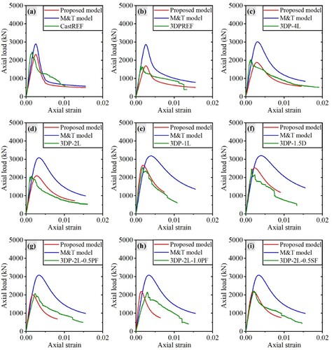
Figure 10. Flow chart to determine the axial strain – load relationship of RC-SC-3DPF.
5. Summaries and conclusions
This paper proposed a new approach combining the steel cable reinforcement method and the reinforced concrete confined by the 3D concrete printing (3DCP) formwork method. This approach was applied to the column case which is regarded as the reinforced concrete confined by the steel cable reinforced 3DCP permanent formwork (RC-SC-3DPF). Axial compression tests and theoretical analysis were conducted to investigate the axial performances of RC-SC-3DPF. The corresponding conclusions can be summarised as follows:
Axial compression test results showed that the failure modes of RC-SC-3DPF are different from those of the case of the traditionally reinforced concrete column without 3DCP formwork (CastREF) and the case of the steel rebar reinforced column confined by 3DCP formwork without steel cables (3DPREF). During tests, the steel cables in 3DCP formwork ruptured, which revealed that the anchorage length of steel cables is sufficient to guarantee the bond between interlayers and steel cables.
Typical axial strain – load diagrams of RC-SC-3DPF were obtained from axial compression tests. It was found that in the post-peak stage, a step-mode descending curve could be observed, which corresponds to the process of steel cables rupturing and 3DCP formwork debonding from the inner cast concrete. A gentle descending curve followed by the step-mode descending curve, which corresponds to transverse steel rebars (TSRs) activated. At this stage, the longitudinal steel rebars (LSRs) and the concrete core of RC-SC-3DPF resist the axial load, which is similar to the structural behaviour of CastREF after the concrete cover spalls.
The detailed axial compression test results presented that as the steel cable confinement ratio (Cf) increases from 0 to 0.671%, the normalised peak load of RC-SC-3DPF linearly increases from 0.71 to 1.04 with the normalised strain ductility roughly linearly decreasing from 2.22 to 0.98, indicating that when steel cable Cf is less than 0.534%, the increasing steel cable Cf makes the structural behaviour of RC-SC-3DPF closer to that of CastREF, while when Cf is larger than 0.534%, the increase in steel cable Cf may lead RC-SC-3DPF possess an even higher peak load resistance compared to CastREF.
The detailed axial compression test results also showed that as the steel fibre vol.% increases from 0 to 0.5%, the normalised peak load increases from 0.84 to 0.90 with a limited ductility loss. In comparison, as polyvinyl alcohol (PVA) fibre vol.% increases from 0 to 1.0%, the normalised strain ductility significantly decreases from 1.28 to 0.92 with a limited peak load resistance improvement. Hence, steel fibre has more potential to be applied to improve the structural performances of RC-SC-3DPF than PVA fibre.
The existing standards of EC-4, ACI-318-19, and AISC-LRFD-2010 were applied to predict the axial peak load resistance. It was found that EC-4 provides the most reasonable prediction of the peak load resistance of CastREF. Consequently, when evaluating the axial performances of tested samples, a reduction factor of 0.85 should be used to consider the negative effects of concrete cover spalling on the axial load resistance.
It was found that the M&T model significantly overestimates the axial load resistance of the tested specimens, which can be caused by ignoring the negative effects of the 3DCP formwork debonding and spalling. To effectively evaluate the axial performances of RC-SC-3DPF, a new model (from Eq.(24) to Eq.(27)) was proposed based on the axial compression test results, existing standards, and the M&T model, which contains three factors: Rf1, Rf2, and Rf3. Rf1 is the reduction factor to consider the spalling of 3DCP formwork negatively affecting the axial load resistance, Rf2 was proposed to account for the effects of steel cable Cf, fibre content, and fibre type on the axial load resistance, and Rf3 was proposed to consider effects of steel cable Cf, fibre content, and fibre type on the strain ductility. It showed that the proposed model presents a relatively good prediction of the axial performances of RC-SC-3DPF, which proved the feasibility of the proposed model in evaluating the structural performances of RC-SC-3DPF.
Acknowledgements
This research is supported by the National Research Foundation, Prime Minister’s office, Singapore, under its Medium-Sized Centre funding scheme, Singapore Centre for 3D Printing, Chip Eng Seng Corporation Ltd., and CES_INNOVFAB Pte. Ltd.
Disclosure statement
No potential conflict of interest was reported by the author(s).
Data availability statement
Data available on request from the authors.
Additional information
Funding
References
- Liu Z, Li M, Quah TKN, et al. Comprehensive investigations on the relationship between the 3D concrete printing failure criterion and properties of fresh-state cementitious materials. Additive Manufacturing. 2023;76:103787. doi:10.1016/j.addma.2023.103787
- Liu Z, Li M, Moo GSJ, et al. Effect of nanostructured silica additives on the extrusion-based 3D concrete printing application. Journal of Composites Science. 2023;7(5):191. doi:10.3390/jcs7050191
- Mohan MK, Rahul AV, Schutter GD, et al. Extrusion-based concrete 3D printing from a material perspective: a state-of-the-art review. Cem Concr Compos. 2021;115:103855. doi:10.1016/j.cemconcomp.2020.103855
- Tay YWD, Panda B, Paul SC, et al. 3D printing trends in building and construction industry: a review. Virtual Phys Prototyp. 2017;12(3):261–276. doi:10.1080/17452759.2017.1326724
- Weng Y, Li M, Ruan S, et al. Comparative economic, environmental and productivity assessment of a concrete bathroom unit fabricated through 3D printing and a precast approach. J Clean Prod. 2020;261:121245. doi:10.1016/j.jclepro.2020.121245
- Liu Z, Li M, Wong TN, et al. Determine the effects of pore properties on the mechanical performances of 3D concrete printing units with experimental and numerical methods. Journal of Building Engineering. 2024;92:109730. doi:10.1016/j.jobe.2024.109730
- Tay YWD, Lim JH, Li M, et al. Creating functionally graded concrete materials with varying 3D printing parameters. Virtual Phys Prototyp. 2022;17(3):662–681. doi:10.1080/17452759.2022.2048521
- Mechtcherine V, Buswell R, Kloft H, et al. Integrating reinforcement in digital fabrication with concrete: A review and classification framework. Cem Concr Compos. 2021;119:103964. doi:10.1016/j.cemconcomp.2021.103964
- Li Z, Hojati M, Wu Z, et al. A fresh and hardened properties of extrusion-based 3D-printed cementitious materials: a review. Sustainability. 2020;12(14):5628. doi:10.3390/su12145628
- Hack N, Lauer WV. Mesh-mould: robotically fabricated spatial meshes as reinforced concrete formwork. Architectural Design. 2014;84(3):44–53. doi:10.1002/ad.1753
- Souza MT, Ferreira IM, Guzi de Moraes E, et al. 3D printed concrete for large-scale buildings: an overview of rheology, printing parameters, chemical admixtures, reinforcements, and economic and environmental prospects. Journal of Building Engineering. 2020;32:101833. doi:10.1016/j.jobe.2020.101833
- Marchment T, Sanjayan J. Mesh reinforcing method for 3D concrete printing. Autom Constr. 2020;109:102992. doi:10.1016/j.autcon.2019.102992
- Baz B, Aouad G, Leblond P, et al. Mechanical assessment of concrete – steel bonding in 3D printed elements. Constr Build Mater. 2020;256:119457. doi:10.1016/j.conbuildmat.2020.119457
- Li Z, Wang L, Ma G. Mechanical improvement of continuous steel microcable reinforced geopolymer composites for 3D printing subjected to different loading conditions. Compos Part B Eng. 2020;187:107796. doi:10.1016/j.compositesb.2020.107796
- Lim JH, Panda B, Pham Q-C. Improving flexural characteristics of 3D printed geopolymer composites with in-process steel cable reinforcement. Constr Build Mater. 2018;178:32–41. doi:10.1016/j.conbuildmat.2018.05.010
- Li Z, Ma G, Wang F, et al. Expansive cementitious materials to improve micro-cable reinforcement bond in 3D concrete printing. Cem Concr Compos. 2022;125:104304. doi:10.1016/j.cemconcomp.2021.104304
- Gebhard L, Mata-Falcón J, Anton A, et al. Structural behaviour of 3D printed concrete beams with various reinforcement strategies. Eng Struct. 2021;240:112380. doi:10.1016/j.engstruct.2021.112380
- Marchment T, Sanjayan J. Bond properties of reinforcing bar penetrations in 3D concrete printing. Autom Constr. 2020;120:103394. doi:10.1016/j.autcon.2020.103394
- Vantyghem G, De Corte W, Shakour E, et al. 3D printing of a post-tensioned concrete girder designed by topology optimization. Autom Constr. 2020;112:103084. doi:10.1016/j.autcon.2020.103084
- Salet TAM, Ahmed ZY, Bos FP, et al. Design of a 3D printed concrete bridge by testing. Virtual Phys Prototyp. 2018;13(3):222–236. doi:10.1080/17452759.2018.1476064
- Du S, Teng F, Zhuang Z, et al. A BIM-enabled robot control system for automated integration between rebar reinforcement and 3D concrete printing. Virtual Phys Prototyp. 2024;19(1). doi:10.1080/17452759.2024.2332423
- Teng F, Li M, Zhang D, et al. BIM-enabled collaborative-robots 3D concrete printing to construct MiC with reinforcement. HKIE Trans. 2023;30(1):106–115. doi:10.33430/V30N1THIE-2022-0023
- Zhu B, Nematollahi B, Pan J, et al. 3D concrete printing of permanent formwork for concrete column construction. Cem Concr Compos. 2021;121:104039. doi:10.1016/j.cemconcomp.2021.104039
- Chen Y, Zhang W, Zhang Y, et al. 3D printed concrete with coarse aggregates: built–in–stirrup permanent concrete formwork for reinforced columns. J Build Eng. 2023;70:106362. doi:10.1016/j.jobe.2023.106362
- Wang L, Yang Y, Yao L, et al. Interfacial bonding properties of 3D printed permanent formwork with the post-casted concrete. Cem Concr Compos. 2022;128:104457. doi:10.1016/j.cemconcomp.2022.104457
- Mander JB, Priestley MJ, Park R. Theoretical stress-strain model for confined concrete. J Struct Eng. 1988;114(8):1804–1826. doi:10.1061/(ASCE)0733-9445(1988)114:8(1804)
- Obaidat AT, Ashour A, Galal K. Stress-Strain behavior of C-shaped confined concrete masonry boundary elements of reinforced masonry shear walls. J Struct Eng. 2018;144(8). doi:10.1061/(ASCE)ST.1943-541X.0002120
- Xu N, Qian Y. Effects of fiber volume fraction, fiber length, water-binder ratio, and nanoclay addition on the 3D printability of strain-hardening cementitious composites (SHCC). Cem Concr Compos. 2023;139:105066. doi:10.1016/j.cemconcomp.2023.105066
- Pham L, Tran P, Sanjayan J. Steel fibres reinforced 3D printed concrete: influence of fibre sizes on mechanical performance. Constr Build Mater. 2020;250:118785. doi:10.1016/j.conbuildmat.2020.118785
- Weng Y, Li M, Wong TN, et al. Synchronized concrete and bonding agent deposition system for interlayer bond strength enhancement in 3D concrete printing. Autom Constr. 2021;123:103546. doi:10.1016/j.autcon.2020.103546
- Bos FP, Bosco E, Salet TAM. Ductility of 3D printed concrete reinforced with short straight steel fibers. Virtual Phys Prototyp. 2019;14(2):160–174. doi:10.1080/17452759.2018.1548069
- Weng Y, Li M, Liu Z, et al. Printability and fire performance of a developed 3D printable fibre reinforced cementitious composites under elevated temperatures. Virtual Phys Prototyp. 2019;14(3):284–292. doi:10.1080/17452759.2018.1555046
- ASTM. C39 standard test method for compressive strength of cylindrical concrete specimens. American Society for Tesing and Materials; 2020. doi:10.1520/c0039_c0039m-20
- ASTM. E8 standard test methods for tension testing of metallic materials, American Society for Tesing and Materials; 2022. doi:10.1520/e0008_e0008m-22
- AlAjarmeh OS, Manalo AC, Benmokrane B, et al. Axial performance of hollow concrete columns reinforced with GFRP composite bars with different reinforcement ratios. Compos Struct. 2019;213:153–164. doi:10.1016/j.compstruct.2019.01.096
- Eid R, Paultre P. Compressive behavior of FRP-confined reinforced concrete columns. Eng Struct. 2017;132:518–530. doi:10.1016/j.engstruct.2016.11.052
- He L, Chow WT, Li H. Effects of interlayer notch and shear stress on interlayer strength of 3D printed cement paste. Additi Manuf. 2020;36:101390. doi:10.1016/j.addma.2020.101390
- Hu X-Z. An asymptotic approach to size effect on fracture toughness and fracture energy of composites. Eng Fract Mech. 2002;69(5):555–564. doi:10.1016/S0013-7944(01)00102-3
- Tian H, Zhou Z, Zhang Y, et al. Axial behavior of reinforced concrete column with ultra-high performance concrete stay-in-place formwork. Eng Struct. 2020;210:110403. doi:10.1016/j.engstruct.2020.110403
- AlAjarmeh OS, Manalo AC, Benmokrane B, et al. Effect of spiral spacing and concrete strength on behavior of GFRP-reinforced hollow concrete columns. J Compos Constr. 2020;24(1). doi:10.1061/(ASCE)CC.1943-5614.0000987
- Yang Y, Wu C, Liu Z, et al. Mechanical anisotropy of ultra-high performance fibre-reinforced concrete for 3D printing. Cem Concr Compos. 2022;125:104310. doi:10.1016/j.cemconcomp.2021.104310
- Xu N, Qian Y, Yu J, et al. Tensile performance of 3D-printed strain-hardening cementitious composites (SHCC) considering material parameters, nozzle size and printing pattern. Cem Concr Compos. 2022;132:104601. doi:10.1016/j.cemconcomp.2022.104601
- Piscesa B, Attard MM, Prasetya D, et al. Modeling cover spalling behavior in high strength reinforced concrete columns using a plasticity-fracture model. Eng Struct. 2019;196:109336. doi:10.1016/j.engstruct.2019.109336
- Wang Y, Liu F, Yu J, et al. Effect of polyethylene fiber content on physical and mechanical properties of engineered cementitious composites. Constr Build Mater. 2020;251:118917. doi:10.1016/j.conbuildmat.2020.118917
- Khan M, Rana MM, Zhang Y, et al. Compressive behaviour of engineered cementitious composites and concrete encased steel composite columns. J Constr Steel Res. 2020;167:105967. doi:10.1016/j.jcsr.2020.105967
- BSI. Eurocode 4: design of composite steel and concrete structures. London: British Standards Institution; 2004.
- ACI. ACI 318–19: building code requirements for structural concrete and commentary, American Concrete Institute USA; 2019.
- AISC-LRFD. Specification for structural steel buildings. Chicago (IL): American Institute of Steel Construction; 2010.
- Cai J, Pan J, Li X. Behavior of ECC-encased CFST columns under axial compression. Eng Struct. 2018;171:1–9. doi:10.1016/j.engstruct.2018.05.090
- Teng JG, Lin G, Yu T. Analysis-Oriented stress-strain model for concrete under combined FRP-steel confinement. J Compos Constr. 2015;19(5). doi:10.1061/(asce)cc.1943-5614.0000549