Abstract
There is a need for standardization of radiostereometric (RSA) investigations to facilitate comparison of outcome reported from different research groups. In this document, 6 research centers have agreed upon standards for terminology, description and use of RSA arrangement including radiographic set-up and techniques. Consensus regarding minimum requirements for marker stability and scatter, choice of coordinate systems, and preferred way of describing prosthetic micromotion is of special interest. Some notes on data interpretation are also presented. Validation of RSA should be standardized by preparation of protocols for assessment of accuracy and precision. Practical issues related to loading of the joint by weight bearing or other conditions, follow-up intervals, length of follow-up, radiation dose, and the exclusion of patients due to technical errors are considered. Finally, we present a checklist of standardized output that should be included in any clinical RSA paper.
This document will form the basis of a detailed standardization protocol under supervision of ISO and the European Standards Working Group on Joint Replacement Implants (CEN/TC 285/WG4). This protocol will facilitate inclusion of RSA in a standard protocol for implant testing before it is released for general use. Such a protocol—also including other recognized clinical outcome parameters—will reduce the risk of implanting potentially inferior prostheses on a large scale.
Since its introduction in 1974 (Selvik Citation1989), radiostereometry (RSA) has been widely used. Its main use has been the assessment of joint replacements. It is a highly accurate, true three-dimensional method of quantifying the motion between an implant and the host bone, for assessment of motion between bony structures that have been fixed and for measuring wear.
Continuous implant migration has been predictive of long-term implant survival and, for most devices, measurement over 2 years provides a surrogate outcome measure with relatively low numbers of subjects, e.g. 15–25 patients in each group in randomized studies (Kärrholm et al. Citation1994a, Ryd et al. Citation1995). Small numbers of subjects can be used in these studies as a consequence of the high accuracy of the measurement technique. Because of this, RSA is an important technique for assessment of joint replacement.
RSA has been applied in many studies primarily conducted in Sweden and in the other Scandinavian countries, and the basis of the technique has been described in several articles and theses (Kärrholm Citation1989, Selvik Citation1989, Kärrholm et al. Citation1997, Börlin Citation2000, Valstar Citation2001). More than 5,000 patients have been included in several studies and more than 300 scientific papers have been published. Topics that have been studied by RSA include: prosthetic fixation (Ryd Citation1992), joint stability and joint kinematics (Uvehammer et al. Citation2000), fracture stability (Ragnarsson and Kärrholm Citation1991), skeletal growth (Hägglund et al. Citation1986), vertebral motion (Pearcy Citation1985), and spinal fusion (Johnsson et al. Citation1990).
Over the years, several groups have developed their own RSA software and hardware (Kärrholm Citation1989, Ryd and Toksvig-Larsen Citation1993, Vrooman et al. Citation1998, Alfaro-Adrián et al. Citation1999). Currently, three systems are available commercially: UmRSA (RSA Biomedical, Umeå, Sweden) (Börlin et al. Citation2002), WinRSA (Tilly Medical Products, Lund, Sweden), and RSA-CMS (MEDIS Medical Imaging Systems BV, Leiden, the Netherlands) (Valstar et al. Citation2000). In addition, several systems have been developed for in-house use (Kiss et al. Citation1995, Alfaro-Adrián et al. Citation1999), or for non-commercial use between research groups.
With a growing number of centers publishing on RSA, there is a need to assure that results are comparable and presented in a similar way. In addition, validation of equipment and software, and follow-up protocols should be standardized. This can only be done when guidelines for standardization of clinical RSA studies have been drawn up.
Our article is a first step in the direction of standardization of RSA, and is not intended to be conclusive. At the end of this article, a list has been added with data that should be included in each clinical RSA study (Appendix: Standard Output). Working Group 4 of the European Standards Organisation Committee on surgical implants (CEN/TC 285/WG4) hopes to produce a standard on migration of joint replacement implants, and it is hoped that the material in this article will form the basis of a related standard on the protocol for RSA measurement.
Basic RSA issues
Terminology
We suggest that the names radiostereometry, radiostereometric analysis, and roentgen stereophotogrammetric analysis are used as synonyms. The abbreviation RSA will always be used to mean all three.
Points or objects of measurement
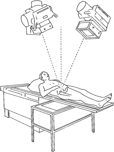
Spherical tantalum markers are used almost exclusively to serve as well-defined landmarks. They are inserted into bone and may be attached to implants (). Standard markers have diameters of 0.5, 0.8 and 1.0 mm. A scientific report should contain information about marker diameters, because this is of importance for visualization and for the precision of measurements. Larger markers result in a larger X-ray image; this larger projection in turn holds more information, which results in higher precision. But they also have a less well defined contour and a less well defined profile, because the marker image is the result of a central projection with an X-ray source of a definite size.
Figure 1. For accurate definition of positions of bone and prosthesis, tantalum markers are inserted in the bone tissue and markers are attached to or inserted into the prosthesis.

At least 3 non-colinear markers should be used to mark each rigid body under study. However, because of the fact that markers can be obscured by metal objects, and a redundancy of markers will increase the precision of the measurements, we advise the use of about 6–9 well-scattered bone markers for each bony structure. Because of manufacturing issues, the number of prosthesis markers is kept to a minimum: in most instances 3 markers are attached. When migration of cement is studied, care should be taken in marking the cement. Markers should not be obscured by the metal of the prosthesis, and in order to avoid galvanic corrosion the markers should not be in contact with the prosthesis. The exact location of the markers will depend on several factors, but this consideration lies outside the scope of these guidelines.
Two other objects commonly used to define prosthetic positions are the femoral head of hip stems and a circular indicator inserted into a cemented polyethylene acetabular cup.
Recently, there have been several developments in order to avoid attaching markers to prostheses. In these so-called model-based RSA techniques, the position of the prosthesis is assessed by matching a virtual projection of a three-dimensional model of the prosthesis to the actual radiographic projection of the prosthesis (Valstar et al. Citation2001, Kaptein et al. Citation2003). If these model-based techniques are to be used, they should have been properly evaluated and the precision or accuracy of these measurements should have been accounted for in peer-reviewed journals.
Radiographic arrangement
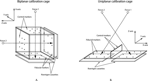
A number of radiographic arrangements can be used. Most often, a uniplanar or a biplanar technique is used. Uniplanar technique means that the recording media (e.g. film cassettes, film plates or some kind of digital detector) are placed side-by-side (). In the most commonly used biplanar technique, the recording media are placed at a 90-degree angle relative to each other. Any other arrangement should be described in detail. Preferably, it should also be stated whether ceiling-mounted or mobile X-ray tubes have been used.
Figure 2. A uniplanar RSA arrangement. Two X-ray tubes are focused on the joint under examination. A calibration cage is placed underneath the X-ray table. It holds two X-ray films positioned next to each other.
Calibration cages and reference plates
Routinely, biplanar calibration cages (; e.g., cage 10, RSA Biomedical; cage 21, Tilly Medical Products) or uniplanar calibration cages (; e.g., cage 43, RSA Biomedical; cage 41; Tilly Medical Products; Carbon Box, MEDIS) are used. If the investigators use cages not previously described, this should be stated in the paper. The data should include the dimensions of the cage, the accuracy of marker placement on the cage, and the cage material. If calibration examinations and reference plates have been used, the same data should be presented for the reference plates. If any other type of cage is employed, these specific cages should also be evaluated in phantom studies.
Figure 3. a) A biplanar RSA arrangement, and b) a uniplanar RSA arrangement.
Radiographs
Radiographs can either be analog or digital. If the authors use analog radiographs in combination with manual measurements, the accuracy of the measuring table should be stated. If analog images have been scanned, it is important that the spatial resolution and gray-scale resolution are presented. If direct digital imaging systems have been used, again information on the spatial and gray-scale resolution should be presented. Information about the devices used should also be given.
Software
To compute the three-dimensional position of bone markers, prostheses or parts of prostheses, several different software packages are available. These software packages should have appropriate documentation and validation of their accuracy and precision. This should be provided by the producer of the software, but additional independent validation studies would be valuable. If the authors use custom-made software, this software should be properly documented.
Methodology issues
Stability and distribution of markers
The stability and distribution of marker beads within a rigid body will influence the accuracy of the motion calculation. The mean error of rigid body fitting is commonly used to assess the stability of markers. It is the mean difference between the relative distances of markers in a rigid body in one examination compared to that in another examination. This proposal suggests that the upper limit for the mean error of rigid body fitting should be 0.35 mm. The distribution of markers can be assessed using the condition number (Söderkvist and Wedin Citation1993, Citation1994). High condition numbers indicate poor marker distribution, while low condition numbers indicate appropriate marker distribution. The long experience from Sweden suggests that condition numbers below 100–110 are very reliable, and sufficient for determination of prosthetic migration. In practice, the Swedish groups almost never use condition number above 130–150. Thus, we suggest an upper limit of 150 for the condition number. The magnitude of the condition number should always be related to the stability of the markers (the magnitude of the mean error of the rigid body fitting).
The upper limit of the condition number cannot be completely rigid in examinations of small joints or bones, however. In examinations of the cervical spine or finger joints, condition numbers higher than 150 have been used (Ryd et al. Citation2000). For studies in which these high condition numbers are accepted, it is essential that the precision of the measurements is validated.
Coordinate systems
The calibration cage defines the position and orientation of the global coordinate system. The position of the reference rigid body within the global coordinate system will be different at each measurement. In RSA, this difference is accounted for by applying a transformation (Selvik Citation1990, Söderkvist and Wedin Citation1993). The patient or the part of the body of interest should be aligned to the global coordinate system to obtain meaningful data. Preferably, a standardized and generally accepted reference position should be used. If not, the position used should be described. This alignment of the patient must be done during at least one of the follow-up evaluations that will be used subsequently as reference examination. To obtain optimum precision, it is preferable to maintain a standardized patient position throughout a series of examinations.
The choice of reference rigid body when calculating relative motion can be arbitrary, depending on the specific question under study. When prosthetic motion (migration, inducible displacements) is studied, the host bone should be considered to be the reference rigid body.
Micromotion
There are several different ways of presenting micromotion results. This can either be as orthogonal translations and rotations, or as Maximum Total Point Motion (MTPM) and helical axes. Translations can be presented for the center of gravity of a rigid body, or for single points in a rigid body. In this section, the most commonly used methods of describing micromotion of implants are presented and guidelines for proper data presentation are given.
Translations
The description of motion of one rigid body relative to another can be given in a number of ways. Translations can be expressed concisely as the components of motion along the orthogonal directions. For most implants, the medial-lateral (X), distal-proximal (Y), and posterior-anterior (Z) directions are meaningful ().
Figure 4. A schematic overview of the use of coordinate systems in defining micromotions of hip implants. Pay special attention to lateral-medial translation, internal rotation and adduction. These have to change sign in order to be able to compare these parameters for prostheses implanted at the left side and right side.
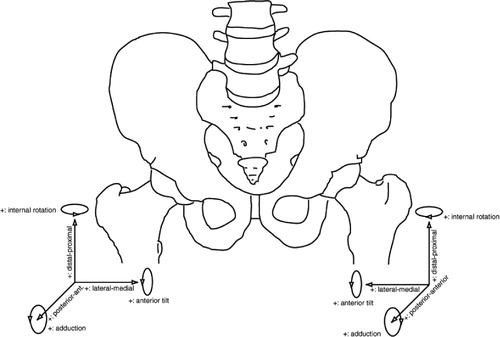
For the anatomical situation, we propose that this definition be used, set in the right-hand side of the body, with positive X being medial, positive Y being superior and positive Z being anterior. Using this convention, left-hand extremities can be dealt with by reversing the X-axis, so that data are given in terms of anatomical directions (). The same holds for rotations of left hand extremities; here, the rotations about the Y-axis and Z-axis should change sign to comply with anatomical directions. However, all calculations should be performed respecting the orthogonal right-hand coordinate system.
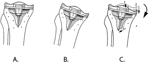
When translations are presented, it is mandatory to account for the chosen point of measurement, either a single marker or the center of gravity of a rigid body. The point(s) used to calculate translations of a rigid body should be standardized and used at all follow-up occasions in all patients ().
Figure 5. The position and orientation of the tibia and the tibial component are defined in the reference RSA radiograph at t1 (A.). In an RSA radiograph made at t2, the position and orientation of the tibia will not be exactly the same as at t1 (B.). In order to assess the micromotion of the implant between t1 and t2, the bone markers must be matched onto each other, and the micromotion—in this case, rotation—of the implant can be assessed (indicated by the curved arrow). In some studies, only translations of single points of a rigid body are presented. One should be cautious in using this approach: the translation of point 2 is greater than the translation of point 1 (points indicated by black dots; translations indicated by straight arrows). The direction of the translation of point 3 is completely different from the translations of points 1 and 2. Thus, the same points of measurement should be used in all patients.
Maximum total point motion
Maximum total point motion (MTPM) represents the length of the translation vector of the point in a rigid body that has the greatest motion. Thus, it can only have positive values, and is not normally distributed. The reason for using MTPM is that in many cases, motion implies a biological effect of some kind and this effect is liable tobe greatest at the point of maximum motion.
When using MTPM, one should be aware that MTPM not only depends on the amount of motion but also on the location of the points of measurement. If these points do not correspond between two different implant designs, any comparison will become incorrect. In successive follow-up measurements, one should be aware that different points in the body may have experienced the greatest motion. In addition, MTPM is highly sensitive to marker loosening in the moving segment. To overcome this last problem, fictive markers should be used to assess MTPM (Nilsson and Kärrholm Citation1993, Regner et al. Citation2000).
Rotations
The rotation matrix is a mathematical expression of the three-dimensional rotation of a rigid body. This matrix is difficult to interpret clinically. Thus, it needs to be resolved in rotations about three orthogonal axes. According to Euler's rotation theorem, any rotation may be described using three angles. It is important to define the sequence of angle calculation, since the values generated will be sequence-dependent. This does not have much effect when studying micromotion of implants, and rotations are most often smaller than 5°—but with larger rotation there is a highly significant influence. The proposal for Euler rotation sequence is XYZ, in which the rotation about the X-axis is effectively flexion-extension, the rotation about the Y-axis is external-internal rotation, and rotation about the Z-axis is abduction-adduction. As stated in the section on translation, we define positive rotations for the right-hand extremities: for left-hand extremities, rotations about the Y-axis and Z-axis should change sign to comply with anatomical directions ().
In a given rotation sequence, each calculated Euler angle depends on the preceding ones. Thus, if the patient alignment is different from the standard, it is incorrect to simply permutate the angles. For example, if the patient transverse axis is aligned to the Z-axis of the cage during an extension-flexion examination, it is incorrect to take the Z-rotation as the flexion-extension angle, since it is affected by the X- (abduction-adduction) and Y- (external-internal) angles. The correct solution is to (mathematically) rotate the patient 90° about the Y-axis before calculating Euler angles.
In the cases in which gimbal-lock is a problem, we propose that quaternions should be used for internal calculation and that these should then be transformed into the above Euler angles for easier interpretation.
Helical axes
The motion of an object from one position to another can be broken down into a rotation about, and a translation along, the instantaneous axis of rotation. (One exception will be when the object shows pure translation but no rotation.) This instantaneous axis of rotation is often called the helical axis (screw axis). To obtain reasonable accuracy, the recorded rotation must be at least 4° (Kärrholm et al. Citation1994b). Thus, helical axes should not be used for describing micromotion of implants, but may be of value if the motions are sufficiently pronounced (e.g. presence of clinical loosening). Helical axes are more commonly used to describe joint kinematics.
Signed versus unsigned (absolute) values
In RSA, translation and rotation parameters (except for MTPM and helical axes) are commonly presented as signed values, which means that the values can be positive or negative. We recommend that signed values should always be used, because when unsigned (absolute, only positive) values are used, several methodological problems will be introduced that are related to the effect of errors (see paragraph on MTPM above). However, when unsigned values are used anyway, one should be aware that they are not normally distributed, and that one cannot present confidence intervals of these parameters as mean ± SD. We propose that when unsigned values are used, means, medians and min-max ranges should be quoted.
Validation of RSA
Introduction
The high accuracy and precision of RSA are the main reasons that small-scale studies can be performed. In order to obtain an objective view of the performance of RSA systems, these systems should be validated in a standardized manner. Several approaches have been used in validation studies (Østgaard et al. Citation1997, Vrooman et al. Citation1998, Valstar et al. Citation2000, Börlin et al. Citation2002). In these studies, either a phantom was positioned in very accurately known positions or the results of a new RSA system were compared to the results of an existing RSA system.
We propose to standardize the validation of the accuracy of RSA systems by using a phantom in which relative translations and rotations can be carried out with high accuracy on a micromotion scale, as well as on a macromotion scale. A description of a phantom and validation experiments lies outside the scope of these guidelines, and will be given in a separate document. For validation of the precision of RSA systems, our advice would be to use double examinations. We emphasize that phantom experiments that are used to assess accuracy are absolutely not an alternative to double examinations that are used to assess clinical precision. All papers giving RSA results should then quote the validation results for each of the standardized tests described in paragraphs that follow on, which can be done very concisely. As results, the mean, median and 95% confidence intervals should be quoted.
Accuracy
The accuracy of RSA can be determined by comparison with another method that has a resolution substantially better than that of RSA (preferably with an error of a few μm). Such determinations are important in radiostereometry, and especially when introducing a new RSA method or starting a new RSA laboratory. Different phantoms have been constructed to enable such determinations (Önsten et al. Citation2001, Bragdon et al. Citation2002). Once again, we emphasize that phantom experiments are absolutely not an alternative to double examinations that are used to assess precision in clinical RSA studies.
Precision
Precision is synonymous with repeatability. It should be noted that precision has nothing to do with the ability of a method to determine the true motion of an object, but rather the possibility that an exact repeat of a result can be achieved. Precision is the basis of power calculations and can dictate the number of patients to be included in a study to obtain significant results.
The precision of RSA can be assessed by so-called “double examinations”. Basically, double examinations are two pairs of stereo radiographs of one and the same patient that are made within a time interval of 10–15 minutes. Between the two examinations, the patient should be repositioned within limits that are expected to be encountered during a clinical follow-up study. In this short time interval, the implant should not have moved with respect to the host bone. Due to measurement errors, however, motion will be calculated—thus indicating the precision of the system. As the precision of RSA depends on several factors that might differ between studies, precision should be assessed for each clinical or preclinical RSA study. Because each individual patient has a unique bone marker configuration, double examinations should be made for each individual patient.
For research groups performing several studies of similar character, and when there have not been any changes that could affect precision, precision assessed for one study could be transferred to another study. However, this cannot be done when a particular calibration cage has been used in one study and another calibration cage has been used in a subsequent study.
In some countries, it is difficult to obtain approval from the medical ethics committee for making double examinations, because of the additional radiation exposure for the patient. However, in our opinion it is unethical not to know the precision of RSA for a particular study, since without knowing it the power calculations cannot be done correctly. This might result in flaws in the conclusions drawn from an RSA study. According to Ranstam et al. (Citation2000), precision and accuracy are the same when zero motion is studied. To avoid confusion, however, we would recommend the use of either precision, “accuracy of zero motion” or “detection limit” when the results of double examinations are reported (Ranstam et al. Citation2000).
Practical issues
Weight bearing
The position of the patient may influence the results of a clinical RSA study. Thus, the positioning of patients should be standardized on the basis of joint type in order to make results from RSA studies comparable. Weight bearing—or more precisely, load bearing—can affect fixation, especially in bone impaction grafting in revision surgery (Ornstein et al. Citation2000, Nelissen et al. Citation2002), and in studies evaluating bony integration with surface coatings. Due to the wide variety of lower limb studies, whether weight bearing is used will depend on practicality issues and study design. Accurate reporting of the subject position or pose is required for all RSA articles. Weight bearing is obviously vital for wear studies in which the wear of polyethylene components is derived from the relative positions of the metallic components (Kellett et al. Citation2004).
Follow-up intervals
For most clinical RSA studies, follow-up examinations are commonly scheduled to take place within the first week postoperatively, and at 6 weeks, 3 months, 6 months, 1 year and 2 years. For some studies, it might be beneficial to extend the number of follow-up examinations during the first 6 months of the follow-up period. This might be the case in studies in which surface coatings, expected establish mechanical bonding to the bone tissue, or impaction grafting are being evaluated (Ornstein et al. Citation2000, Nelissen et al. Citation2002).
Mobilization of a patient influences the micromotion of the implant under study. It is therefore essential that it be clearly stated whether the baseline RSA radiograph has been taken before or after mobilization. It should be emphasized that in a study in which the subject or the groups are compared, the initiation of the RSA examinations should be standardized as far as possible to avoid any bias caused by different observation time in the early phase after the operation. The migration of devices is often stated in terms of rate. The length of the observation period will influence calculation of this outcome. In clinical practice, it is impossible to examine patients at the exact time point that was decided upon for the study protocol. However, in order to be able to compare the results of different patients and of different studies, the window tolerance for examination intervals should be as tight as possible. The postoperative examination should be undertaken within 5 days of surgery, but before weight bearing, unless otherwise stated. Even though follow-up intervals should be as similar as possible, for practical reasons we allow ± 1 week for follow-up evaluations within the first postoperative year, ± 2 weeks for the 1-year evaluation, ± 3 weeks for the 2-year evaluation up to the 5-year evaluation, and ± 4 weeks for longer follow-up evaluations. If larger time ‘windows’are used, measurements of variance along the time axis should be expressed as follows: × (SD) months.
Length of follow-up
As a result of shortages of funding, many clinical RSA studies of joint replacements are terminated after 2 years, but long-term RSA results can provide valuable insights into the loosening process of implants. To date, only two studies have proven the relationship between short-term loosening detected with RSA and long-term aseptic loosening (Kärrholm et al. Citation1994a, Ryd et al. Citation1995). In order to gain more insight into this relationship, more long-term RSA studies are needed. We recommend follow-up on an annual basis after the second postoperative year, or at least after 5, 10, 15 and 20 years. If all research is directed toward this goal, the insights gained in these long-term RSA studies will not only benefit the patients, but also the manufacturers of implants.
Radiation dose
The radiation doses for most standard RSA examinations—such as examinations of the hip, the knee and the spine—have been evaluated, and have proven to be lower than for the corresponding conventional examinations. However, the true radiation dose is not standardized but depends on a number of factors that might vary between research centers. Thus, the radiation dose of an examination should be assessed and presented to the local ethics committee, and should be available on request.
RSA radiographs are exposed with higher voltage and lower current than conventional radiographs. Non-conventional projections are often used, and cage markers may disturb analysis of morphological changes. Thus, these radiographs can usually not be used for diagnostic purposes in clinical practice.
Exclusion of patients due to technical shortcomings
There are several reasons for excluding patients from clinical follow-up studies. Due to the technical character of RSA studies, patients can be excluded as a result of technical shortcomings such as poor image quality, poor bone marking, over-projection of markers, etc. It is essential that the reasons for exclusion of patients should be documented. The clinical and radiographic follow-up of these excluded patients should, of course, be guaranteed.
Future directions
With these guidelines for standardization of RSA, we would like to make a first step. With this approach, our intention is to make it possible to compare the outcome of RSA studies that have been done by different research groups, using different RSA software and different RSA arrangements. As a result, we expect the importance of the outcome of clinical RSA studies to become even stronger.
Working group 4 of the CEN Technical Committee on Surgical Implants (CEN/TC 285/WG 4) intends to develop standards for the measurement of implant migration, which would be expected to be adopted by ISO in due course. This might open a pathway towards inclusion of RSA in a standard protocol for implant testing. By doing so, standardized preclinical testing will have been extended to standardized early clinical testing before an implant is released for general use. As a result, the risk of implanting potentially inferior prostheses in patients will be reduced, resulting in less suffering for patients and a reduction in healthcare expenses.
- Alfaro-Adrián J, Gill H S, Murray D W. Cement migration after THR. A comparison of charnley elite and exeter femoral stems using RSA. J Bone Joint Surg (Br) 1999; 81: 130–4
- Börlin N. Model-based measurements in digital radiographs. Umeå University, UmeåSweden 2000, Thesis
- Börlin N, Thien T, Kärrholm J. The precision of radiostereometric measurements. Manual vs. digital measurements. J Biomech 2002; 35: 69–79
- Bragdon C R, Malchau H, Yuan X H, Perinchief R, Kärrholm J, Börlin N, Estok D M, Harris W H. Experimental assessment of precision and accuracy of radio stereometric analysis for the determination of polyethylene wear in a total hip replacement model. J Orthop Res 2002; 20: 688–95
- Hägglund G, Bylander B, Hansson L I, Kärrholm J, Selvik G, Svensson K. Longitudinal growth of the distal fibula in children with slipped capital femoral epiphysis. J Pediatr Orthop 1986; 6: 274–7
- Johnsson R, Selvik G, Strömqvist B, Sunden G. Mobility of the lower lumbar spine after posterolateral fusion determined by roentgen stereophotogrammetric analysis. Spine 1990; 15: 347–50
- Kaptein B L, Valstar E R, Stoel B C, Rozing P M, Reiber J H. A new model-based RSA method validated using CAD models and models from reversed engineering. J Biomech 2003; 36: 873–82
- Kärrholm J. Roentgen stereophotogrammetry. Review of orthopedic applications. Acta Orthop Scand 1989; 60: 491–503
- Kärrholm J, Borssen B, Lowenhielm G, Snorrason F. Does early micromotion of femoral stem prostheses matter? 4-7-year stereoradiographic follow-up of 84 cemented prostheses. J Bone Joint Surg (Br) 1994a; 76: 912–7
- Kärrholm J, Jonsson H, Nilsson K G, Söderqvist I. Kinematics of successful knee prostheses during weight-bearing: three-dimensional movements and positions of screw axes in the Tricon-M and Miller-Galante designs. Knee Surg Sports Traumatol Arthrosc 1994b; 2: 50–9
- Kärrholm J, Herberts P, Hultmark P, Malchau H, Nivbrant B, Thanner J. Radiostereometry of hip prostheses. Review of methodology and clinical results. Clin Orthop 1997, 344: 94–110
- Kellett C F, Short A, Price A, Gill H S, Murray D W. In vivo measurement of total knee replacement wear. The Knee 2004; 11(3)183–7
- Kiss J, Murray D W, Turner-Smith A R, Bulstrode C J. Roentgen stereophotogrammetric analysis for assessing migration of total hip replacement femoral components. Proc Inst Mech Eng [H ] 1995; 209: 169–75
- Nelissen R G, Valstar E R, Poll R G, Garling E H, Brand R. Factors associated with excessive migration in bone impaction hip revision surgery: a radiostereometric analysis study. J Arthroplasty 2002; 17: 826–33
- Nilsson K G, Kärrholm J. Increased varus-valgus tilting of screw-fixated knee prostheses. Stereoradiographic study of uncemented versus cemented tibial components. J Arthroplasty 1993; 8: 529–40
- Önsten I, Berzins A, Shott S, Sumner D R. Accuracy and precision of radiostereometric analysis in the measurement of THR femoral component translations: human and canine in vitro models. J Orthop Res 2001; 19: 1162–7
- Ornstein E, Franzen H, Johnsson R, Sundberg M. Radiostereometric analysis in hip revision surgery-optimal time for index examination. 6 patients revised with impacted allografts and cement followed weekly for 6 weeks. Acta Orthop Scand 2000; 71: 360–4
- Østgaard S E, Gottlieb L, Toksvig-Larsen S, Lebech A, Talbot A, Lund B. Roentgen stereophotogrammetric analysis using computer-based image-analysis. J Biomech 1997; 30: 993–5
- Pearcy M J. Stereo radiography of lumbar spine motion. Acta Orthop Scand 1985, Suppl 212: 1–45
- Ragnarsson J I, Kärrholm J. Stability of femoral neck fracture. Roentgen stereophotogrammetry of 29 hook-pinned fractures. Acta Orthop Scand 1991; 62: 201–7
- Ranstam J, Ryd L, Önsten I. Accurate accuracy assessment: review of basic principles. Acta Orthop Scand 2000; 71: 106–8
- Regner L, Carlsson L, Kärrholm J, Herberts P. Tibial component fixation in porous- and hydroxyapatite-coated total knee arthroplasty: a radiostereo metric evaluation of migration and inducible displacement after 5 years. J Arthroplasty 2000; 15: 681–9
- Ryd L. Roentgen stereophotogrammetric analysis of prosthetic fixation in the hip and knee joint. Clin Orthop 1992, 276: 56–65
- Ryd L, Toksvig-Larsen S. Early postoperative fixation of tibial components: an in vivo roentgen stereophotogrammetric analysis. J Orthop Res 1993; 11: 142–8
- Ryd L, Albrektsson B E, Carlsson L, Dansgard F, Herberts P, Lindstrand A, Regner L, Toksvig-Larsen S. Roentgen stereophotogrammetric analysis as a predictor of mechanical loosening of knee prostheses. J Bone Joint Surg (Br) 1995; 77: 377–83
- Ryd L, Yuan X H, Lofgren H. Methods for determining the accuracy of radiostereometric analysis (RSA). Acta Orthop Scand 2000; 71: 403–8
- Selvik G. Roentgen stereophotogrammetry. A method for the study of the kinematics of the skeletal system. Acta Orthop Scand 1989, Suppl 232: 1–51
- Selvik G. Roentgen stereophotogrammetric analysis. Acta Radiol 1990; 31: 113–26
- Söderkvist I, Wedin P A. Determining the movements of the skeleton using well-configured markers. J Biomech 1993; 26: 1473–7
- Söderkvist I, Wedin P A. On condition numbers and qlgorithms for determining a rigid-body movement. Bit 1994; 34: 424–36
- Uvehammer J, Kärrholm J, Brandsson S. In vivo kinematics of total knee arthroplasty. Concave versus posterior-stabilised tibial joint surface. J Bone Joint Surg (Br) 2000; 82: 499–505
- Valstar E R. Digital roentgen stereophotogrammetry. Leiden University Medical Center, LeidenThe Netherlands 2001, Thesis
- Valstar E R, Vrooman H A, Toksvig-Larsen S, Ryd L, Nelissen R G. Digital automated RSA compared to manually operated RSA. J Biomech 2000; 33: 1593–9
- Valstar E R, de Jong F W, Vrooman H A, Rozing P M, Reiber J H. Model-based roentgen stereophotogrammetry of orthopaedic implants. J Biomech 2001; 34: 715–22
- Vrooman H A, Valstar E R, Brand G J, Admiraal D R, Rozing P M, Reiber J H. Fast and accurate automated measurements in digitized stereophotogrammetric radiographs. J Biomech 1998; 31: 491–8
Appendix: Standardized output
To facilitate comparison between different centres using the same method, the items listed below should be used to account for the results of a clinical RSA study.
The units used for translation should always be millimetres and the units used for rotations should be degrees.
The accuracy and precision of the arrangement used should be presented. Measurement interval and window tolerance should be quoted.
Type of calibration cage (object) and use of reference plates should be given.
It should be stated whether fixed or portable X-ray sources were used.
Positioning of subject, calibration cage (object), X-ray tubes and X-ray cassettes should be standardized or described in detail. Orientation of the global coordinate system should be presented.
Method of image acquisition should be stated, e.g. whether scanned (then scanner details should to be given) or whether digital radiographs have been used (then system details should be given).
Software used should be stated, and if appropriate which version.
Size of marker beads used should be given (and validation results should be reported for the sizes used in the study).
The method of determining the position of the implant, whether based on attached beads, geometrically or model-based should be stated. If appropriate, reference to any new/novel technique should be given.
The following should be stated: cut-off level for condition number and rigid body fitting error for exclusion of subjects from study.
Rigid body fixed coordinate frames and angular rotation sequence should be defined.
The precision of the measurements assessed by double examinations of all patients enrolled in the study should be stated.
Migration/motion data should be given in terms of translations and angular rotations. All 6 degrees of freedom should be reported. If not, these data should be available from the authors on request. The point(s) used to measure translations should be indicated (either a single point of a rigid body or the center of gravity of a rigid body), standardized, and its (their) location(s) on the implant (or in the bone) should always be presented.