Abstract
Background and purpose Hip resurfacing arthroplasty is being used more and more frequently. The small ratio in size between the resurfaced femoral head and the relatively thick femoral neck raises the question of whether the range of motion is sufficient, particularly with regard to the high mobility required by younger patients. We analyzed motion in a CAD model.
Methods Three-dimensional CAD models of the natural hip were created from CT scans and 8 designs of hip resurfacing prostheses (head diameter between 42 mm and 54 mm combined with a hemispherical cup) were implanted in a virtual sense. We simulated 3 different leg positions and the range of motion was evaluated, considering five different implant positions.
Results The range of motion of the hip resurfacing designs analyzed was far below the range of motion of stemmed total hip prostheses. None of the resurfacing prostheses provided flexion movements of 90° without impingement. The average range of motion of hip resurfacing arthroplasty was 31–48° below the range of motion of a stemmed total hip replacement with 32-mm head diameter.
Interpretation The range of motion of the hip resurfacing designs examined was substantially less than that of a conventional total hip prosthesis. Since impingement of the femoral neck on the acetabular component increases the risk of neck fractures, of dislocation and of subsequent implant loosening, the design and position of the implant should be considered before using hip resurfacing arthroplasty as a standard treatment for younger patients.
Since advanced manufacturing processes have enabled a lower wear rate in metal-on-metal prostheses, the number of hip resurfacing arthroplasties has increased (Beaule et al. Citation2006, Silva et al. Citation2004). However, some surgeons are opposed to hip resurfacing due to the high rate of femoral neck fractures (Mont et al. Citation2006, Rubash Citation2007), increased release of metal ions (Witzleb et al. Citation2006), and greater surgical exposure than standard total hip arthroplasty (THA). This, combined with the steep learning curve, is considered to be disadvantageous for patients (Rubash Citation2007). Other surgeons who approve of hip resurfacing point out that there is conservation of femoral bone stock (Amstutz et al. Citation2006), a low wear rate (Schmalzried Citation2007), and the possibility to exchange hip resurfacing with a stemmed standard prosthesis with less sacrifice of bone stock compared to the revision of a conventional THA (Amstutz et al. Citation2007, Schmalzried Citation2007). The minimal bone loss and the good revision options appear to be indications for consideration of hip resurfacing arthroplasty, especially in younger patients with osteoarthritis of the hip.
Younger patients are more active and demand higher mobility, which raises the question of whether hip resurfacing enables an adequate range of motion (ROM) of the artificial joint. A series of experimental (Bader et al. Citation2004a, Citationb), computational (Bader et al. Citation2002), and finite-element (Scifert et al. Citation2001, Nadzadi et al. Citation2003, Stewart et al. Citation2004, Kluess et al. Citation2007a, Citationb) studies on the ROM of standard THR systems have led to the conclusion that dislocation and impingement of the femoral neck are caused by implant design and implant positioning. One main finding regarding the influence of implant design was that a large prosthetic head combined with a small neck diameter enables the maximum ROM before impingement and gives the highest dislocation stability (Bader et al. Citation2004b). Finite-element analyses of standard prostheses have shown that impingement of the prosthetic neck on the rim of the cup causes high stresses that can lead to plastic deformation of polyethylene and metallic components as well as brittle fracture of ceramic implants (Kluess et al. Citation2007b). Besides impingement, a low ROM can lead to subluxation, which is associated with increased contact pres-sures—and consequently to a higher wear rate and early failure. Early impingement of standard THRs can lead to total dislocation of the hip, which is the second most frequent complication of hip replacement (Robbins et al. Citation2001). In hip resurfacing arthroplasty, impingement is associated with complications such as neck fractures and subluxation (Rudert et al. Citation2007).
We have not been able to find any experimental or finite-element studies concerning the ROM and impingement behavior of hip resurfacing arthroplasty. In hip resurfacing arthroplasty, it is unclear whether the relatively thick neck of the femur in combination with a prosthetic head diameter smaller than the anatomical femoral head diameter provokes early impingement. We present a computational study concerning the ROM of different designs of hip resurfacing arthroplasty. The results are compared to the ROM of a conventional stemmed prosthesis with a 32-mm head.
Method
Using a three-dimensional computer-aided-design (CAD) system, the ROM of hip resurfacing arthoplasty was analyzed with regard to head size, cup geometry, and implant positioning. The analysis was performed simulating three different leg maneuvers: (1) maximum flexion, (2) maximum internal rotation at 90° flexion, and (3) maximum external rotation at 15° adduction and 10° extension. The two latter maneuvers are clinically related to prosthetic impingement and total hip dislocation (Kummer et al. Citation1999). Hip resurfacing head sizes of 42 mm, 48 mm, 50 mm, and 54 mm were analyzed. The design of the implant components was assessed according to the geometric dimensions ().
Figure 1. Design features of the hip resurfacing implants analyzed.
Head coverage was varied with angles of φ=180° and φ=165° of the acetabular component for all head sizes. The femoral component was adapted to the anatomical neck diameter Dneck, depending on the height, a, of the spherical cut. The height of the spherical cut is the distance between the center of rotation of the implant and the distal opening of the femoral component. The outer diameter of the acetabular component Dcup was 6 mm larger than its inner diameter, resulting in a wall thickness of 3 mm. The radius r of the internal rounding of the acetabular component was 1 mm. The design features of the 8 computer-generated models of hip resurfacing prostheses that were analyzed are summarized in . The implant positions studied were set according to , including positions within the safe zone and also steep, retroverted, and highly anteverted cup positions for analysis of worst-case scenarios. The head was modelled with 0° anteversion in all simulations.
Table 1. Variations in hip resurfacing design features, pre- and postoperative head-neck ratio, and postoperative femoral offset
To create anatomically accurate CAD models of the hip joint, computed-tomography (CT) scans of 3 patients, which had been made for diagnostic reasons apart from this study, were used. The CT scans were chosen (1) according to the size of the patient's femoral head in order to gain optimum fit of the hip resurfacing prosthesis, and (2) according to the age of the patient in order to take into account the fact that hip resurfacing is the preferred therapy for younger patients. The median age of the patients chosen was 53 years. The bony structures in the CT scans were segmented using AMIRA software (Mercury Computer Systems, Chelmsford, MA). After the bony structures were marked in all slices of the CT scans, a three-dimen-sional reconstruction of the femur and the pelvis was performed, creating triangulated surfaces. To achieve a better performance of the CAD simulation, the triangulated surfaces of the femur and the pelvis were converted to NURBS (non-uniform rational B-spline surfaces) using the software Geomagic Studio (Raindrop Geomagic, Research Triangle Park, NC). The virtual implantation of the hip resurfacing and analysis of the ROM were performed using the CAD software Pro/ENGINEER (Parametric Technology Corporation, Needham, MA). The pelvis and the femur were oriented in a Cartesian coordinate system with the x-axis connecting the right and left spinae iliacae anterior superior (SIAS), the z-axis touching the pubic symphysis and pointing cranially, and the origin located in the sagittal plane between the SIAS. A sphere was fitted onto the femoral head in order to determine the center of rotation of the hip joint and the patient's anatomical head diameter. In addition, the minimum circular cross section around the femoral neck without contact with the cortical bone was approximated in order to achieve an optimum fit of the resurfacing prostheses with minimum lesion of the cortical bone. Based on these results, the patient's anatomical head-neck ratios were recorded ().
Afterwards, the origin of the Cartesian coordinate system was translated into the center of rotation of the hip. The femoral component of the hip resurfacing was modeled according to the design features already mentioned and was then placed in the appropriate position, maintaining the physiological center of the hip joint. The femur was resected using a Boolean operation, with the femoral component placed at the center of rotation in a CCD (caput-collum-diaphysis) angle of 135°. The femoral offset (the normal distance between the diaphyseal axis and the center of the hip joint) and the vertical offset (the vertical distance between the tip of the greater trochanter and the center of the hip joint) were measured (). The acetabular component was rotated around the appropriate angles of inclination and anteversion (), and the femur together with the femoral component was moved to the starting position of the leg maneuver to be analyzed. Subsequently, the maneuvers were carried out until prosthetic or bony impingement occurred and the maximum ROM was recorded. The CAD model of the 48-mm hip resurfacing prosthesis and the surrounding bone in the starting position and in the end position of flexion is shown in . The resurfacing prostheses with 48 mm and 50 mm were both simulated in the hip joint of the same patient to analyze the effect of choosing one size larger than the best-fit size for operation.
Figure 2. Anterolateral view of the CAD model of a 48-mm hip resurfacing reduced by 5%. The femoral offset implant with 165° head coverage in situ, with a cup position of 45° inclina-rose with the patient's femoral tion and 15° anteversion. Left: starting position for flexion movement with a head size. The diagrams in Figure straight leg. Right: end position with an anterior impingement of femoral neck at the acetabular component (flexion angle: 77°).
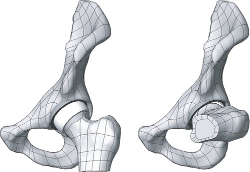
Table 2. Implant positions analyzed
In order to compare the results to those of a standard THR, the same maneuvers were performed using a model of a 32-mm head diameter endoprosthesis from a previous study (Kluess et al. Citation2007b). The standard THR consisted of a hemispherical cup with 180° head coverage, a spherical head with no skirt and no additional offset, and a 14-mm prosthetic neck. The stem was simulated in 0° version. The standard THR and the resurfacing prosthesis with a head diameter of 48 mm were analyzed using morphological data from the same patient.
Results
After virtual implantation of the implant components, the average anatomical head-neck ratio was reduced by 5%. The femoral offset rose with the patient's femoral head size. The diagrams in give an overview of maximum ROM for flexion, maximum ROM for internal rotation at 90° flexion, and maximum ROM for external rotation at 15° adduction and 10° extension, all with a cup position of 45° inclination and 15° anteversion. This case represents a recommended implant position (Bader et al. Citation2002) within the safe zone (Lewinnek et al. Citation1978). None of the hip resurfacing implants analyzed allowed a flexion movement of 90°, which is why the second maneuver, internal rotation at 90° flexion, had to be carried out from a negative rotation angle in order to make comparison possible.
Figure 3. Overview of range of motion of all implant designs analyzed in 45° inclination and 15° anteversion of the cup. Left: maximum flexion. Middle: maximum internal rotation at 90° flexion, starting from 40° external rotation. Right: maximum external rotation in 15° adduction and 10° extension (b.i.: bony impingement). The dashed line marks physiological ROM (Genoud et al. Citation2000, Tannast et al. Citation2007).
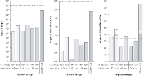
The results for maximum flexion for all implant designs studied in all implant positions analyzed are summarized in . In all cases, the ROM of the hip resurfacing prostheses was far below the ROM of the conventional stemmed endoprosthesis with a 32-mm head. The flexion ROM of the hip resurfacing prostheses with 180° of head coverage was 48° lower on average than that of the conventional endoprosthesis. Reducing the head coverage to 165° resulted in a higher flexion ROM, but the average values were still 37° below those of the conventional prosthesis.
Table 3. Maximum flexion angles of all implant designs analyzed in all implant positions simulated
For the reasons already mentioned, the results for internal rotation in 90° of flexion were limited to a few implant positions. The cases in which it was not possible to achieve a flexion angle of 90°, even with a highly externally rotated femur, are marked in . Internal rotation in 90° flexion of the hip resurfacing implants with 180° head coverage was 40° lower on average than conventional THR. The ROM of hip resurfacing implants with 165° head coverage was about 31° lower.
Table 4. Maximum ROM for internal rotation at 90° flexion of all implant designs analyzed in all implant positions simulated
With external rotation in 15° adduction and 10° extension, some simulations revealed bony impingement between the greater trochanter and the os ischii (). The ROM until bony impingement rose with head size. When bony impingement occurred, the simulation was carried on to investigate the theoretical ROM until the neck impinged on the rim of the cup. Except for a few cases with anteverted cups, the theoretical ROM of the conventional prosthesis was above the ROM until bony impingement (). In contrast, the ROM of the hip resurfacing implants was considerably lower, which is why prosthetic impingement occurred before bony impingement in many cases. The analyses of the 50-mm head diameter resurfacing prosthesis was conducted to determine whether a higher ROM can be achieved with an implant of one size larger than the best-fitting one. As shown in , there was a minor increase in ROM (1.2° on average) using a larger implant with morphological data from the same patient.
Table 5. Maximum ROM for external rotation at 15° adduction and 10° extension for all implant designs analyzed in all implant positions simulated. Where bony impingement occurred before prosthetic impingement, the theoretical values for prosthetic impingement are shown in parentheses
Discussion
We found a substantial decrease in ROM with hip resurfacing prostheses compared to conventional stemmed total hip prostheses. The large diameter of the neck of the femur led to early impingement in all maneuvers analyzed. Simulation of hip resurfacing arthroplasty resulted in a decrease in head-neck ratio of 5% compared to the natural hip joint. In addition, in the natural hip joint the large diameter of the neck does not limit the ROM at such a high level due to the specific geometry of the natural acetabulum, where the rim of the acetabulum is partially cut out to enable more movement before impingement. In hip resurfacing, the thickness of the wall of the acetabular component limits the head size. Moreover, the neck diameter should not be reduced surgically since a lesion of the supporting cortical bone increases the risk of fracture (Amstutz et al. Citation2004b, Rudert et al. Citation2007).
We chose the geometry of the implant designs to be analyzed such that a minimum possible neck diameter without cortical lesions would be achieved. The height of the spherical cut (measurement a) was set depending on the head size. While the smallest head diameter of 42 mm had the spherical cut 8 mm away from the center of rotation, the largest head was cut at 12 mm. Since the height of the spherical cut determined the neck diameter, there was no increase in ROM with larger heads. Enlargement of the head diameter by 2 mm resulted in a minor increase in ROM of 1.2°. Recent studies (Bader et al. Citation2004b, Crowninshield et al. Citation2004, Kluess et al. Citation2007b) have shown that larger heads provide a higher ROM, but only with an identical neck diameter. In hip resurfacing arthroplasty, the neck diameter must normally increase with the head size if the aim is to conserve acetabular bone.
It has been shown that over the years hip resurfacing, the neck diameter decreases due to mechanically optimized bone remodeling of the femur (Lilikakis et al. Citation2005). A reduced neck diameter could lead to higher ROM. However, within the first few months postoperatively soft tissue and bony impingement can occur. Surgical factors influencing joint instability include femoral offset, anteversion, and the location of the center of the hip joint. We found that patients with a higher femoral offset had increased ROM before bony impingement occurred (). In addition to patient-spe-cific and surgical factors, implant-related factors contribute to the functional outcome. With the hip resurfacing designs studied here, the patient would not achieve flexion movements of 90° without impingement, and furthermore no internal rotation at 90° flexion, particularly in the case of flat or retroverted cup positions. The large head diameters of hip resurfacing prostheses provide joint stability (Shimmin et al. Citation2005). Compared to THA, the dislocation rate of hip resurfacing prostheses is reported to be very low (Amstutz et al. Citation2004a, Duijsens et al. Citation2005, Shimmin et al. Citation2005). The stresses appearing at the impingement site can, however, lead to further complications (Rudert et al. Citation2007), which include damage to the bone, fracture of the femoral neck, and implant loosening. Also, subluxation caused by impingement can damage the bearing surfaces and initiate high wear rates (Kluess et al. Citation2007b).
We believe that our findings should be carefully considered before hip resurfacing arthroplasty is adopted as a standard procedure in young patients.
No competing interests declared.
DK: writing of article, performing analysis, technical support; CZ: performing analysis; TL: technical support; WM: initiation of the study, professional support; KPS: professional support in simulation and design; RB: initiation of the study, planning of study design, professional support.
- Amstutz H C, Beaule P E, Dorey F J, Le Duff M J, Campbell P A, Gruen T A. Metal-on-Metal Hybrid Surface Arthroplasty: Two to Six-Year Follow-up Study. J Bone Joint Surg (Am) 2004a; 86(1)28–39
- Amstutz H C, Campbell P A, Le Duff M J. Fracture of the neck of the femur after surface arthroplasty of the hip. J Bone Joint Surg (Am) 2004b; 86(9)1874–7
- Amstutz H C, Beaule P E, Dorey F J, Le Duff M J, Campbell P A, Gruen T A. Metal-on-Metal Hybrid Surface Arthroplasty. Surgical Technique. J Bone Joint Surg (Am) 2006; 88: 234–49
- Amstutz H C, Antoniades J T, Le Duff M J. Results of metal-on-metal hybrid hip resurfacing for Crowe type-I and II developmental dysplasia. J Bone Joint Surg (Am) 2007; 89(2)339–46
- Bader R, Steinhauser E, Gradinger R, Willmann G, Mittelmeier W. Computer-based motion simulation of total hip prostheses with ceramic-on-ceramic wear couple. Analysis of implant design andorientation as influence parameters. Z Orthop Ihre Grenzgeb 2002; 140(3)310–6
- Bader R, Scholz R, Steinhauser E, Busch R, Mittelmeier W. Method for the evaluation of factors influencing the dislocation stability of total hip endoprotheses. Biomed Tech 2004a; 49(5)137–44
- Bader R, Scholz R, Steinhauser E, Zimmermann S, Busch R, Mittelmeier W. The influence of head and neck geometry on stability of total hip replacement: a mechanical test study. Acta Orthop Scand 2004b; 75(4)415–21
- Beaule P E, Campbell P, Lu Z, Leunig-Ganz K, Beck M, Leunig M, Ganz R. Vascularity of the arthritic femoral head and hip resurfacing. J Bone Joint Surg (Am) 2006; 88(Suppl 4)85–96
- Crowninshield R D, Maloney W J, Wentz D H, Humphrey S M, Blanchard C R. Biomechanics of large femoral heads: what they do and don't do. Clin Orthop 2004, 429: 102–7
- Duijsens A W, Keizer S, Vliet-Vlieland T, Nelissen R G. Resurfacing hip prostheses revisited: failure analysis during a 16-year follow-up. Intern Orthop 2005; 29(4)224–8
- Genoud P, Sadri H, Dora C, Bidaut L, Ganz R, Hoffmeyer P (2000) The hip joint range of motion: a cadaveric study. 12th ESB conference, Dublin, 2000, 137
- Kluess D, Martin H, Mittelmeier W, Schmitz K, Bader R. Finite-Element-analysis into impingement-related implant failure of total hip replacement. Materials Testing 2007a; 49(6)330–6
- Kluess D, Martin H, Mittelmeier W, Schmitz K P, Bader R. Influence of femoral head size on impingement, dislocation and stress distribution in total hip replacement. Med Eng Phys 2007b; 29(4)465–71
- Kummer F J, Shah S, Iyer S, DiCesare P E. The effect of acetabular cup orientations on limiting hip rotation. J Arthroplasty 1999; 14(4)509–13
- Lewinnek G E, Lewis J L, Tarr R, Compere C L, Zimmerman J R. Dislocations after total hip-replacement arthroplasties. J Bone Joint Surg (Am) 1978; 60(2)217–20
- Lilikakis A K, Vowler S L, Villar R N. Hydroxyapatite-coated femoral implant in metal-on-metal resurfacing hip arthroplasty: minimum of two years follow-up. Orthop Clin North Am 2005; 36(2)215–22
- Mont M A, Ragland P S, Etienne G, Seyler T M, Schmalzried T P. Hip resurfacing arthroplasty. J Am Acad Orthop Surg 2006; 14(8)454–63
- Nadzadi M E, Pedersen D R, Yack H J, Callaghan J J, Brown T D. Kinematics, kinetics, and finite element analysis of commonplace maneuvers at risk for total hip dislocation. J Biomech 2003; 36(4)577–91
- Robbins G M, Masri B A, Garbuz D S, Greidanus N, Duncan C P. Treatment of hip instability. Orthop Clin North Am 2001; 32(4)593–610
- Rubash H E. Resurfacing Arthroplasty: Time to consider it again? No. Proceedings of the AAOS. 2007; 9–10
- Rudert M, Gerdesmeyer L, Rechl H, Juhnke P, Gradinger R. Resurfacing arthroplasty of the hip. Orthopade 2007; 36(4)304–10
- Schmalzried T P. Resurfacing Arthroplasty: Time to consider it again? Yes. Proceedings of the AAOS. 2007; 8
- Scifert C F, Noble P C, Brown T D, Bartz R L, Kadakia N, Sugano N, Johnston R C, Pedersen D R, Callaghan J J. Experimental and computational simulation of total hip arthroplasty dislocation. Orthop Clin North Am 2001; 32(4)553–67
- Shimmin A J, Bare J, Back D L. Complications associated with hip resurfacing arthroplasty. Orthop Clin North Am 2005; 36(2)187–93
- Silva M, Lee K H, Heisel C, dela Rosa M A, Schmalzried T P. The Biomechanical Results of Total Hip Resurfacing Arthroplasty. J Bone Joint Surg (Am) 2004; 86(1)40–6
- Stewart K J, Pedersen D R, Callaghan J J, Brown T D. Implementing capsule representation in a total hip dislocation finite element model. Iowa Orthop J 2004; 24: 1–8
- Tannast M, Kubiak-Langer M, Langlotz F, Puls M, Murphy S B, Siebenrock K A. Noninvasive three-dimensional assessment of femoroacetabular impingement. J Orthop Res 2007; 25(1)122–31
- Witzleb W-C, Ziegler J, Krummenauer F, Neumeister V, Guenther K-P. Exposure to chromium, cobalt and molybdenum from metal-on-metal total hip replacement and hip resurfacing arthroplasty. Acta Orthop 2006; 77(5)697–705