
Abstract
Fibroin is a protein that has been extensively studied for biomedical application. In the present study, silk was dissolved in CaCl2-C2H5OH-H2O in order to obtain silk fibroin (SF) solution, and it was then lyophilized in freeze-dryer. The electrospinning of SF sponge was performed at different fibroin concentrations. SF nanofibers were modified by crosslinking PAMAM dendrimers to carboxylic-terminated fibroin, via EDC and NHS. The modified SF nanofibers scaffold was evaluated by SEM, X-Ray diffraction, FTIR and MTT assay. SEM micrograph showed that the electrospun containing 7% (w/w) fibroin had continuous fibers and an average diameter of 80 nm. Through treatment, conformational transitions of the SF nanofibers from random coil to β-sheet occurred rapidly, confirmed by FTIR and X-Ray diffraction. FTIR spectrum showed amide peaks, which confirmed the existence of fibroin. The modification results of analysis demonstrated that the amino groups were more established on the surface of the SF nanofiber scaffold. Biocompatibility tests were carried out through seeding fibroblasts cell line L929 on nanofibers. Adhesion and proliferation of fibroblasts were investigated by MTT assay, which showed no cytotoxicity. Therefore, fibroin nanofibers scaffolds appear to be a probable choice for potential use in tissue engineering.
1. Introduction
Some of the main problems of human health are related to accidents and illnesses that cause a loss of organ or tissue damages [Citation1]. Tissue engineering tries to resolve these problems by using natural and synthetic polymeric matrices to produce appropriate biomaterial shapes. There are many structures that can be used as biomaterials, e.g. thin films, gels, 3 D sponges as well as micro- and nano-particles [Citation2].
Silk proteins are produced by various species of silkworms, spiders, scorpions and bees [Citation3]. Natural silk from the silkworm cocoons and Bombyx Mori has been used for centuries as biomedical suture material [Citation4]. Silk fibers are built by two proteins, namely, fibroin and sericin. Sericin is the gummy substance surrounding fibroin [Citation5]. For biomedical applications, only silk fibroin is useful, and sericin, due to its immunogenicity, needs to be removed [Citation1]. Silk fibroin is a natural protein and is known to promote cell attachment, proliferation and tissue regeneration. It has been reported that the biological features of silk fibroin make it a very good choice for use for regeneration [Citation6, Citation7]. Silk fibroin has been widely explored in many biomedical applications, due to its impressive biocompatibility, biodegradability and minimal inflammatory reactions [Citation8, Citation9]. Electrospinning is a unique method, capable of producing nanoscale fibers from both synthetic as well as natural polymers for biomedical applications [Citation10, Citation11]. A cylinder collector rotating at a high speed can obtain aligned fiber; a simple and common way, compared to other methods, to obtain aligned fiber [Citation12].
In the present study, silk was dissolved in CaCl2-C2H5OH-H2O in order to obtain silk fibroin solution and it later was lyophilized in a freeze-dryer. The electrospinning of SF sponge was performed with formic acid as a spinning solvent. SF nanofibers were modified by crosslinking PAMAM dendrimers to carboxylic-terminated Fibroin, via EDC and NHS. In order to evaluate the properties of SF nanofibers scaffold prepared by this methods, the dissolve process, morphology, structure, biocompatibility and cytotoxicity were studied.
2. Experimental methods
2.1. Preparation of silk fibroin
Raw silk fibers were degummed twice with 0.05% (w/w) Na2CO3 solution at 100 °C for 30 min and then rinsed thoroughly, three times, with deionized water. This process was repeated in order to completely remove silk sericin from the raw silk fibers.
The degummed silk fibroin (SF) was dissolved in a mixture of solvents, composed of CaCl2-C2H5OH-H2O = 1:2:8 (molar ratio), for 6 h at 75 °C. The solution was then dialyzed in cellulose tubular membrane (molecular cutoff = 8000-14,000 Da, Sigma, USA) against distilled water for three days. The water was changed every 12 h. The SF solution was instantaneously frozen in liquid nitrogen (-196 °C) and then lyophilized for 24 h in a Liobras® freeze-dryer (model L101, Brazil) to obtain SF sponge.
2.2. Electrospinning and Post-Treatment
The SF electrospinning solution was prepared by dissolving the SF sponge in 98% formic acid for 3 h. In the electrospinning process, the SF solutions were placed into the syringe with a stainless needle connected to a high voltage power supplier. A voltage of 8 kV was applied to the stainless needle, and a distance of 10 cm from the syringe tip was employed. All electrospinning experiments were performed with the same processing conditions.
As the voltage increased, a drop of SF solution formed at the tip of the needle, and then, a jet was ejected. With the solvent evaporating, the SF nanofibers formed on the collection screen. Then, for the ethanol treatment, SF nanofibers were immersed in 75/25 (v/v) ethanol/water for 30 min, in order to induce crystallization of SF, and then dried in vacuum at room temperature for 24 h.
2.3. Grafting of PAMAM
Fibroin-PAMAM conjugates were prepared by crosslinking PAMAM dendrimers to carboxylic-terminated fibroin, via EDC and NHS chemistry. EDC and NHS have been utilized widely and in numerous applications such as amino acid coupling. The crosslinking solution was prepared by dissolving EDC/NHS at concentrations of 1.5, 3, 4.5, 6 and 7 w/w % (2/1 = w/w) in 95% ethanol. The samples were placed in EDC/NHS solution for 2 h at 37 °C. The PAMAM grafting solution was achieved by dissolving 7% (W/W) PAMAM G2 in 95% ethanol. The SF nanofibers which were previously treated with EDC and NHS were placed into PAMAM solution in room temperature for 12 h in pH 7 and dried in vacuum at 100 °C for 2 h.
2.4. Cell viability
L-929 cells were cultured in an incubator (5% CO2, 37 °C). The cells were suspended in McCoy's 5 A medium and they were supplemented with 10% Fetal Bovine Serum (FBS) and 1% Penicillin-Streptomycin, with the exception of transfection experiments, where cells were grown in complete media without antibiotics.
The toxicity of PAMAM-grafted SF nanofibers was measured using the MTT assay. The number of viable cells was assayed over a period of 14 days, with the assumption that any toxic effects would be manifested within that period of time. The MTT chromophore represents the number of viable cells, by measuring the amount of formazan generated by the mitochondrial enzymes of metabolically active cells [Citation13]. Thus, the number of viable cells can be correlated with the absorbance at 540 nm (λ max). In order to quantify L-929 cells viability, MTT (50 μL, 5 mg/mL PBS) was added to each well and the plate was incubated for 3 h at 37 °C. After the MTT treatment, the plates were centrifuged at 800 × g for 5 min, the supernatant was removed, and the pellet was washed once with PBS. An extraction buffer (250 μL, 20% SDS/50% DMF, pH 7.4) was added to each well, and the gels were kept at 37 °C, overnight. After solubilization, each well was diluted 10-fold, and aliquoted into one column of 96-well plate. The absorbance was measured at 0, 2, 6, 9 and 14 days, using a microplate spectrophotometer (Molecular Devices), at 550 nm, with the extraction buffer as the blank.
2.5. Characterizing techniques
2.5.1. Scanning electron microscopy (SEM)
The morphology of SF nanofibers scaffold was observed, using SEM (S-5700, Hitachi, Tokyo, Japan). Prior to imaging, the samples were mounted on a copper plate and sputter-coated with 20-30nm thick gold layer. The diameters of the fibers were acquired from SEM images and measured by Image J.
2.5.2. Fourier-Transform infrared spectroscopic analysis (FTIR)
The infrared spectra of modified SF nanofibers scaffold were measured on a FTIR spectrometer, using KBr pellets (Tensor 27 FTIR; Bruker, Ettlingen, Germany). The spectra, with a resolution of 4 cm−1, were recorded and subtracted from the sample readings. The samples were measured in reflection mode; for this purpose, the silk fibroin had been transformed into tablet form.
2.5.3. X-ray diffractometry
The crystalline structure of the SF scaffold, modified with PAMAM dendrimers, and the structure of degummed fibroins were determined by XRD. To this end, an X-ray diffractometer (Siemens, Munich, Germany) was used, with Ni-filtered Cu Kα radiation from 4° to 70° (2θ angle), in steps of 0.02° and a step time of 3 s. The voltage and current of the X-ray source were 30KV and 20 mA, respectively.
3. Results and discussion
3.1. Preparation of SF nanofibers scaffold
shows the microstructure of SF electrospun at different concentrations of SF (5, 7, 9, 11, 13, 15% w/w), determining the optimal percentage of fibrin for preparing the spinning solution for the electrospinning of nanofibers. These values were dissolved in formic acid, and then electrospinning was performed. Afterwards, their morphology was examined by SEM.
Figure 1. Morphologies of SF nanofibers at different concentration: a. 5%; b. 7%; c. 9%; d. 11%; e. 13%; f. 15%.
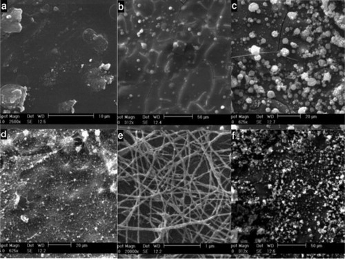
As depicted in , SEM micrographs showed that the electrospun containing 7% (w/w) fibroin had continuous fibers and an average diameter of 80 nm and a distribution ranging in diameter from 30 to 120 nm, obtained through Image J software. This sample showed the best morphology and fiber structure; therefore, it was chosen as the optimal SF concentration for the spinning solution of electrospinning.
When the electrospinning solution had a low viscosity, the solvent jet was changed from continuous to drop-droplet, and electrospinning became electrospraying. Increasing the SF concentration increases the polymer mass in the spinning jet.
In this situation, the viscosity is higher and a stronger connection between the polymer chains is created. By increasing SF concentration, the density of spinning solution also increases. This results in a stronger force to draw the fibers, and the diameter of the fibers is reduced. However, there is a critical limit, after which the increase in concentration will overcome the drawing force of the fibers and changes the morphology of the fiber.
3.2. Surface modification of SF nanofibers
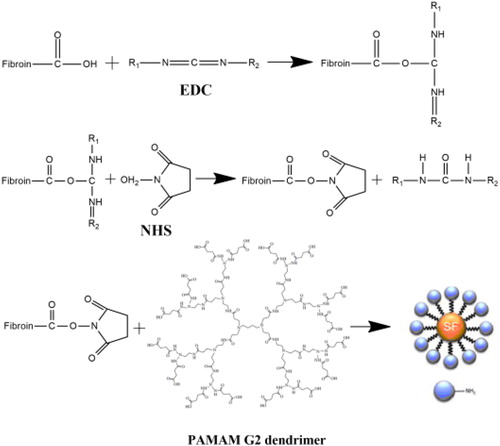
As previously mentioned, surface modification of carboxyl group (–COOH) by the reaction of 1-ethyl-3-(dimethyl-aminopropyl) carbodiimide hydrochloride (EDC) and N-hydroxyl succinimide (NHS) in different concentrations was performed to create cross-linking and develop the amide bonds formation. EDC is a crosslinking agent that binds the carboxyl group to amine groups of fibroin. EDC initially binds to the carboxyl group and forms an unstable Ester. NHS can replace the EDC and form a semi-stable compound, which in the presence of a protein containing the amine group is separated from the carboxyl group and allows the amide bond, which is a covalent bond, to be created ().
Figure 2. The schematic of mechanism of crosslinking of SF with PAMAM G2 by EDC-NHS.
For the purpose of surface modification of SF nanofibers scaffold, the nanofibers were immersed in EDC and NHS for 48 h in different concentrations () and 7% (W/W) dendrimer G2 in ethanol solvent and then washed with deionized water and, lastly, dried.
Table 1. Concentrations of EDC/NHS and PAMAM for surface modification of SF nanofibers scaffold.
By examining the SEM images taken after the treatment of SF nanofibers scaffold (), it was observed that an increase in the concentration of EDC/NHS causes the formation of a layer similar to a film on nanofibers. This is due to the high amount of cross-link materials and increased cross-linking between nanofibers, which prevent the formation of a scaffold with sufficient porosity. By reducing the amount of EDC/NHS, we see that there is a good cross-linking between nanofibers, which results in the creation of a suitable structure for cell culture.
Figure 3. SEM images taken after treatment of SF nanofibers: (a) EDC = 5, NHS = 2.5, (b) EDC = 4, NHS = 2, (c) EDC = 3, NHS = 1.5, (d) EDC = 2, NHS = 1, (e) EDC = 1, NHS = 0.5.
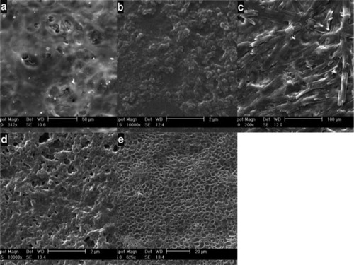
Sample number 5, with EDC = 5, NHS = 2.5 and 7% dendrimer has the best morphology for use as a tissue engineering scaffold, because it has an appropriate three-dimensional structure with a porosity that is ideal for extracellular matrix and cell culture.
3.3. MTT assay
The response and cytotoxicity of modified fibroin scaffolds on L929 cells were investigated by the MTT assay. The MTT assay is based on the reduction of the yellow tetrazolium salt to purple formazan crystals, through dehydrogenase enzymes secreted from the mitochondria of metabolically active cells.
The amount of purple formazan crystals formed is proportional to the number of viable cells [Citation14]. A known concentration of cells was seeded onto fibroin scaffolds. clearly indicates that the SF scaffold did not have any toxic effect on the L929 cells, and the percentage viability of the cells in the scaffolds and in control was at the same level of statistical significance (). These results clearly indicate that SF-based scaffolds are completely nontoxic to cells, and that the scaffolds do not show any adverse effect on the growth of cells. Hence, these scaffolds can be considered suitable for tissue engineering.
Figure 4. MTT assays and cytotoxicity studies against L-929 Cells: (a) Cell viability (%) During 24 h of incubation, (b) Optical microscopy images after incubation with control, (c) Optical microscopy images after incubation with SF nanofibers scaffold.
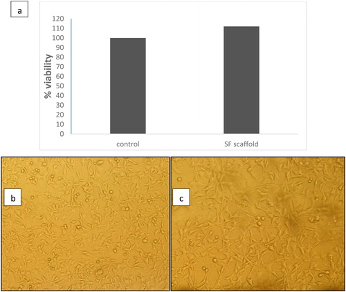
Figure 5. FTIR transmittance spectra of: (A) Degummed silk fibroin. (B) Silk fibroin nanofibers scaffold modified by PAMAM dendrimers.
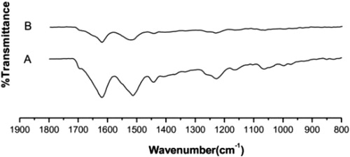
3.5. FTIR
The surface functional groups of the fibroin were deduced using FTIR analysis (). The PAMAM dendrimers present on the scaffold fabricated from SF, as well as pure fibroin were also analyzed by FTIR. In the spectrum of pure SF (), due to the presence of amide groups in fibroin, the band for amide I was observed at 1621 cm−1 (C = O stretching), amide II at 1510 cm−1 (N–H deformation), and amide III at 1231-1445 cm−1 (C–N stretching, C = O bending vibration). All these characteristic absorbance peaks indicate the existence of a hydrogen-bonded NH group. These results indicate a random coil/silk I conformation [Citation7, Citation15]. The result of modified SF nanofibers scaffold by PAMAM dendrimer was obtained by comparing the spectra of pure fibroin and modified SF nanofibers scaffold, where there is a little shifting of bands that represents information about the nature of the intermolecular interaction of the material.
After surface modification of SF nanofibers scaffold by PAMAM dendrimers (), the peak of pure SF with a wavenumber of 1510 cm−1 (amide II) was shifted according to the β-sheet layout of silk fibroin. Subsequently, the SF molecules present in the scaffold could structurally rearrange themselves, due to the variations in hydrogen bonding, resulting in β-sheet conformational change [Citation16]. The detected crystalline structure of modified SF nanofibers scaffold by dendrimers showed more silk I, while that of the pure fibroins showed more silk II.
3.6. X-ray diffraction analysis of the silk fibroins’ crystalline structure
The toughness of silk fibers is dependent on their β-sheet composition. In spider and cocoon silk, the β-sheet consists of a poly-alanine arranged in an anti-parallel or parallel conformation. A previous study by Lu demonstrated that the corresponding D-spacing of silk I (α-form, type II β-turn) were 0.74 nm, 0.56 nm, 0.44 nm, 0.41 nm, 0.36 nm, 0.32 nm, and 0.28 nm, and that of silk II (β-form, anti-parallel β-pleated sheet) were 0.98 nm, 0.48 nm, and 0.43 nm [Citation17].
shows the XRD data of pure SF and modified SF nanofibers scaffolds used in our study. The degummed fibroin showed diffraction peaks, which corresponded to silk II crystalline spacing of 0.48 nm (2θ = 18.5°) and silk I crystalline spacing of 0.38 nm (2θ = 22.3°). In contrast, the fibroin treated with dendrimer showed four obvious diffraction peaks at 2θ, namely 19.5°, 20.4°, 24.5°, and 29.4°, which corresponded to silk I crystalline spacing of 0.44 nm, 0.41 nm, 0.35 nm, and 0.30 nm, respectively. No typical diffraction peaks of silk II were found for this treated silk fibroin. The sharp peak observed at 2θ = 20.4° of treated fibroins indicated an increased crystallization ability of fibroin.
Figure 6. X-ray diffraction patterns of silk fibroins. (A) Pure silk fibroin. (B) Silk fibroin treated with dendrimer.
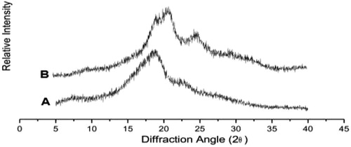
Furthermore, the fibroin nanofibers scaffold treated with PAMAM dendrimers were composed of more silk I (α-form, type II β-turn) than the pure fibroin, which had more silk II (β-form, anti-parallel β-pleated sheet). The standard orientation methods, such as rolling and drawing, are able to transform the metastable silk I into silk II [Citation18]. Therefore, it is possible that the treatment with PAMAM dendrimer is superior in its ability to protect the integrity of the fibroin, maintaining more silk І, and that it has a good capability as scaffold in tissue engineering.
4. Conclusions
In this paper, surface modification by PAMAM dendrimer (G2) and cross-linking by EDC and NHS with silk fibroin (SF) nanofiber scaffold was applied. The preparation of silk fibroin by PAMAM dendrimer, preserved the best original protein structure and produced a good affinity to cell. The surface modification with dendrimer may represent the most appropriate method by which to prepare silk fibroins for use as biomaterials, especially for tissue engineering.
Acknowledgements
We would like to thank Dr. Mazeyar Parvinzadeh for his helpful insights and for polishing this manuscript.
Disclosure statement
There is no conflict to declare.
References
- Sionkowska A, Płanecka A. Preparation and characterization of silk fibroin/chitosan composite sponges for tissue engineering. J Mol Liq. 2013;178:5–14.
- Reddy N, Reddy R, Jiang Q. Crosslinking biopolymers for biomedical applications. Trends Biotechnol. (6)2015;33:362–369.
- Kundu B, Rajkhowa R, Kundu SC, et al. Silk fibroin biomaterials for tissue regenerations. Adv Drug Deliv Rev. (4)2013;65:457–470.
- Fan S, Zhang Y, Shao H, et al. Electrospun regenerated silk fibroin mats with enhanced mechanical properties. Int J Biol Macromol. 2013;56:83–88.
- Bahat P, Nivedita S, Subrata R. Use of sericin of Bombyx mori in the synthesis of silver nanoparticles, their characterization and application. Indian J of Fibre Text Res. 2011;36:168–171.
- Kundu B, Kurland N, Bano S, et al. Silk proteins for biomedical applications: Bioengineering perspectives. Prog Polym Sci. (2)2014;39:251–267.
- Vepari C, Kaplan DL. Silk as a biomaterial. Prog Polym Sci. 2007;32(8–9):991–1007.
- Zhu M, Wang K, Mei J, et al. Fabrication of highly interconnected porous silk fibroin scaffolds for potential use as vascular grafts. Acta Biomater. 2014;10(5):2014–2023.
- Ki CS, Park SY, Kim HJ, et al. Development of 3-D nanofibrous fibroin scaffold with high porosity by electrospinning: implications for bone regeneration. Biotechnol Lett. 2008;30(3):405–410.
- Ayutsede J, Gandhi M, Sukigara S, et al. Regeneration of Bombyx mori silk by electrospinning. Part 3: characterization of electrospun nonwoven mat. Polym. 2005;46(5):1625–1634.
- Liu Z, Zhang F, Ming J. Preparation of electrospun silk fibroin nanofibers from solutions containing native silk fibrils. Appl Poly. 2014;132:1–7.
- Katta P, Alessandro M, Ramsier RD, et al. Continuous electrospinning of aligned polymer nanofibers onto a wire drum collector. Nano Lett. 2004;4(11):2215–2218.
- Mosmann T. Rapid colorimetric assay for cellular growth and survival: Application to proliferation and cytotoxicity assays. J Immunol Methods. (1–2)1983;65:55–63.
- Ghasemi L, Morshed M, Karbalaie KH, et al. Electrospun poly (ε-caprolactone) nanofiber Mat as extracellular matrix. Yakhteh Med. 2008;10(3):179–184.
- Wang X, Wenk E, Matsumoto A, et al. Silk microspheres for encapsulation and controlled release. J Control Release. 2007;117(3):360–370.
- Vasconcelos A, Gomes A, Cavaco-Paulo A. Novel silk fibroin/elastin wound dressings. Acta Biomater. 2012;8(8):3049–3060.
- Lu Q, Hu X, Wang X, et al. Water-insoluble silk films with silk I structure. Acta Biomater. 2010;6(4):1380–1387.
- He SJ, Valluzzi R, Gido SP. Silk I structure in Bombyx mori silk foams. Int J Biol Macromol. 1999;24(2–3):187–195