
Abstract
Objective: Sport research often requires human motion capture of an athlete. It can, however, be labour-intensive and difficult to select the right system, while manufacturers report on specifications which are determined in set-ups that largely differ from sport research in terms of volume, environment and motion. The aim of this review is to assist researchers in the selection of a suitable motion capture system for their experimental set-up for sport applications. An open online platform is initiated, to support (sport)researchers in the selection of a system and to enable them to contribute and update the overview. Design: systematic review; Method: Electronic searches in Scopus, Web of Science and Google Scholar were performed, and the reference lists of the screened articles were scrutinised to determine human motion capture systems used in academically published studies on sport analysis. Results: An overview of 17 human motion capture systems is provided, reporting the general specifications given by the manufacturer (weight and size of the sensors, maximum capture volume, environmental feasibilities), and calibration specifications as determined in peer-reviewed studies. The accuracy of each system is plotted against the measurement range. Conclusion: The overview and chart can assist researchers in the selection of a suitable measurement system. To increase the robustness of the database and to keep up with technological developments, we encourage researchers to perform an accuracy test prior to their experiment and to add to the chart and the system overview (online, open access).
Highlights
The aim of this review is to assist researchers in the selection of a suitable motion capture system for their experimental set-up for sport applications.
An overview of 17 human motion capture systems is provided, reporting the general specifications given by the manufacturer and calibration specifications as determined in peer-reviewed studies.
An open online platform is initiated to support (sport)researchers in the selection of a system and to enable them to contribute and update the overview.
1. Introduction
Sport research often requires human motion capture of an athlete. Human motion capture is the process of recording human movement; this review focusses on recording global position of the body(segments) of an athlete. It can be labour-intensive and difficult to acquire information on the accuracy and practical usage of measurement systems. Specifications reported by manufacturers are determined in conditions and set-ups that diverge from the conditions in which sport research is performed; this can be attributed to four characteristics of the sport research area.
First, sport research is performed in non-laboratory settings, at the field, rink or arena that the sport is practiced on. Such an area outside the controlled laboratory environment brings several challenges, namely different locations (e.g. indoor versus outdoor), weather conditions (e.g. temperature, humidity), measurement interferences (e.g. noise, scattering, magnetic disturbances) and obstacles in the area resulting in occlusion.
Second, the measurement (capture)volume is often large (). Typically, the accuracy is inversely proportional to the coverage of a positioning system (i.e. a lower accuracy for a larger measurement volume), which makes this generally the limiting factor in the selection of a measurement system. When the displacement of the participants becomes larger, ergometers are sometimes used to acquire a large number of movement cycles (Begon, Colloud, Fohanno, Bahuaud, & Monnet, Citation2009). However, this is not always desirable, because movements on an ergometer might differ from the actual motion, or simply because there is no ergometer to replicate the motion on.
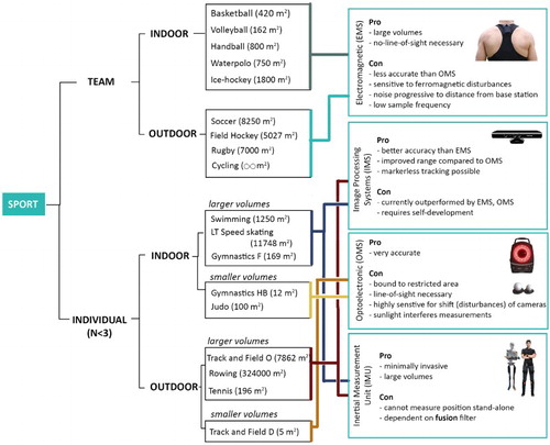
Figure 1. Sport categories with the most plausible measurement system categories. A division is made between team sports (more than three players) and individual sports. Team sports primarily involve large measurement volumes and occlusions. Since team sports are mainly concerned with tracking, the accuracy is less important than for individual sports, where technique factors are commonly analysed. The individual sports are apart from indoor vs. outdoor, also divided into larger and smaller volume sports. Smaller volumes are covered by the highly accurate OMSs. The individual sports in larger volumes are currently the most critical in terms of measuring kinematics. The most suitable options are IMS and IMU (fusion) systems. Gymnastics HB, high bar, gymnastics F, floor, track and field R, rink, track and field D, discus;
Third, research for sport analysis often deals with highly dynamic motions which are more difficult to capture than static or slow movements (e.g. gait analysis). For example, the necessity of high sample frequencies poses a technical challenge. For sport applications, typical sample frequencies are between 50 and 250 Hz (). It has the preference to prevent using too high sample frequencies to avoid excessive amounts of data and to avoid high-frequency noise. Only in specific cases very high frequencies (>1000 Hz) are necessary, e.g. to study impact (such as jumping) or very high-velocity movements (such as baseball pitching). Moreover, the system has to deal with motion dynamics, which, for instance, proves to be problematic in inertial measurement units (IMUs), where linear accelerations can disturb the sensor orientation estimation of sensor fusion algorithms.
Fourth, the size and weight of the sensors are of importance when a measurement system requires placement of sensors, markers, transponders, or tags directly on an athlete. Especially in high performance and high dynamic conditions, an athlete should be minimally hindered in her freedom of actions.
The aim of this paper is to assist researchers in the selection of a suitable motion capture system for their experimental set-up for sport applications. For this purpose, a literature review was conducted on the available human motion capture systems used in peer-reviewed papers on sport analyses. This paper provides an overview of the found measurement systems and their specifications given by the manufacturer (weight and size of the sensors, maximum capture volume, environmental feasibilities), and reports the instrumental errors (accuracy) as determined in the peer-reviewed studies. Furthermore, the working principles of each of the systems are explained, as these determine the system limitations and characteristics. Motion artifacts and data processing, such as body pose reconstruction methods and filtering, fall outside of the scope of this survey. The results are made available via an open online platform, to enable (sport)researchers to contribute and update to the overview on measurement systems.
2. Method
We carried out a literature search between October 2012 and January 2013 and between December 2016 and February 2017. Both searches were performed in the databases of Scopus, Web of Science and Google Scholar using combinations of the keywords of the following three groups. Group 1: measure, analyse, system; Group 2: kinematic, motion, force, coordinate, rotation, orientation, location, position, velocity, speed, acceleration; Group 3: sport, skating, cycling, football, track, field, running, tennis, swimming, hockey, baseball, basketball, skiing and rowing. The search was limited to papers in the English language and published in peer-reviewed journals or conference proceedings. Additional literature was obtained through the reference lists of selected papers.
The abstracts of the retrieved papers were read to verify whether a human motion capture system was used in the work. We focused on papers that use measurement systems in a sport experimental setting. If this was not the case, the paper was excluded from further investigation. The remaining papers were read to obtain information about the accuracy of the measurement system and the context for which this accuracy was determined (environmental conditions, test set-up, type of motion and error definition). If the paper did not include an accuracy evaluation in the experimental context, we tried to retrieve this information from studies referenced by the paper. This information was then included, although not always determined in a sport context, and therefore marked in the results section. If no peer-reviewed papers were found on the accuracy, the paper and system were left out of further evaluation.
The accuracy of a system was set to be the 95th percentile of the instrumental error:
(1) In which
is the reported mean (RMSE was used in case of absence of mean), and
is the reported standard deviation. The range of a system was set to be the area (m2) (global horizontal plane) of the measurement volume. We choose range instead of volume to obtain a general variable for both 2D and 3D systems (Gilgien, Spörri, Limpach, Geiger, & Müller, Citation2014; Monnet, Samson, Bernard, David, & Lacouture, Citation2014; Ogris et al., Citation2012; Waegli & Skaloud, Citation2009).
3. Results
The literature study resulted in a total of 20 peer-reviewed studies on measurement accuracy, discussing 17 different human motion capture systems. The systems are listed in . This table provides the general specifications of the systems regarding environmental capabilities, weight, size and maximum volume as reported by the manufacturers. lists the same systems with the corresponding published studies and the accuracy specifications. The accuracy specifications include the number of cameras, number of markers, sample frequency, reference system, motion, a statistical value, measurement volume or range, and the reported accuracy. These results are processed in the online, interactive selection tool. In , the accuracies are plotted against the range of the experimental set-up. As expected, the accuracy of the systems (equation 1) is inversely proportional to the coverage of a positioning system; in other words, a lower accuracy for a larger measurement volume.
Figure 2. (A) Chart on range versus accuracy as reported in peer-reviewed papers (). Indicated are the ranges of several common sport fields. Note that the reported ranges are not the maximal ranges of measurement systems (for this see ). (B) Selection procedure for a suited measurement system. The graph can be divided into four quadrants, which are defined by the minimal measurement range and the minimal accuracy requirement of the research set-up in question. The upper left area now contains the systems that have a small range and low accuracy, we will refer to them as not applicable (NA). The lower right area contains the systems that satisfy the specific requirements of both range and accuracy, we will refer to those as applicable (A). The lower left area is the area with measurement systems that meet the accuracy requirement, but do not have the required range; we refer to those systems as low in range (LR). The upper right area is the area with systems that meet the range requirement, but lack the right accuracy, referred to as low in accuracy (LA). It might be the case that there are no systems in the chart that meet the volume-accuracy requirements (A). Then, it might be possible to combine systems from the LR or LA quadrant, via sensor integration (Lee, Ohgi, & James, Citation2012). Data from different measurement systems are then combined to determine one variable. For instance, by combining an IMU with GPS, the high sample frequency of the IMU is combined with the position data of the GPS, to compensate for integration drift of the IMU (Brodie, Walmsley, & Page, Citation2008b; Waegli & Skaloud, Citation2009; Xsens, Citation2017). A fusion motion capture system requires a fusion algorithm to combine the data of both measurement units (e.g. a Kalman filter or Comparative filter).
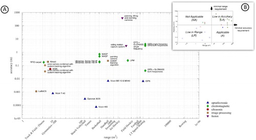
Table 1. General table: specifications of the manufacturers on the measurement systems. Given are the weight and size of the sensors and system, the type of sensor, and the maximum capture volume, number of markers, and sample frequency. The maximum capture volume and sample frequency are given for one camera or sensor; if a system is not restricted by the limitations of the number of sensors, this is indicated by ‘∞’. * indicates that the system was used in sport applications, but the accuracy was determined in a different context (found via reference list of paper).
Table 2. Accuracy table: measurement systems and their accuracy in a certain range, as reported in peer-reviewed articles (column 2). The specifications of the experiment set-up are given in columns 3–7. The last two columns (12–13) report the range and accuracy that are adopted in the chart of ; chosen for this purpose was the maximum reported range (column 9), with the accuracy at 95% confidence interval (P95) (column 10). If the reported statistical values (column 8) did not permit the estimation of P95, this is indicated as a comment in column 11. Note that the maximum range in the peer-reviewed articles is not the maximum capture volumes of a system (for this see the general ).
The specifications in terms of the practical and technological difficulties associated with the types of measurement systems are highly dependent on their physical working principles. In human motion capture, we distinguished five working principles: optoelectronic measurement systems (OMSs), electromagnetic measurement systems (EMSs), image processing systems (IMSs), ultrasonic localisation systems (UMSs) and inertial sensory systems (IMUs) (van der Kruk, Citation2013b). Arranged by these working principles, the measurement systems are explained in the next sections. The general pros and cons of each of the working principles are summarised in .
3.1. Optoelectronic measurement systems
The OMSs are more accurate than the other systems (). Not surprisingly, the optical systems (e.g. Optotrak or Vicon) are in literature often regarded as the gold standard in motion capture (Corazza, Mündermann, Gambaretto, Ferrigno, & Andriacchi, Citation2010). An OMS detects light and uses this detection to estimate the 3D position of a marker via time-of-flight triangulation. The accuracy of the systems is dependent on the following parts of the experimental set-up: the locations of the cameras relative to each other, the distance between the cameras and the markers, the position, number and type of the markers in the field, and the motion of the markers within the capture volume (Maletsky, Sun, & Morton, Citation2007). Also, there is a trade-off between camera resolution and sample frequency.
OMS is based on fixed cameras and can therefore acquire data only in a restricted area (Begon et al., Citation2009). The capture volume is dependent on the maximum number of cameras and the field of view of each camera. The largest measured range with OMS is 824 m2, obtained with a Vicon MX13 measurement system (Spörri, Schiefermüller, & Müller, Citation2016). For this range, 24 cameras were required. This number of cameras results in significant practical difficulties regarding cost, portability, calibration, synchronisation, labour and set-up. Further limitations of the system are the necessity of line-of-sight, which means that the data output will be interrupted when the cameras lose sight of the markers (Panjkota, Stancic, & Supuk, Citation2009; Spörri et al., Citation2016). Furthermore, the systems are highly sensitive to alterations in the set-up, e.g. due to accidental shifting of a camera (Windolf, Götzen, & Morlock, Citation2008). The systems are mostly used in dark areas (indoors) because bright sunlight interferes with the measurements (Spörri et al., Citation2016).
There are two categories within the optoelectronic systems: active marker systems and passive marker systems. Passive systems use markers that reflect light back to the sensor. The Vicon systems in the chart () are examples of passive motion capture systems. Active systems utilise markers that contain the source of light for the sensors (often infrared) (Richards, Citation1999). In the chart, Optotrak 3020 is an active marker optical system. The benefit of active markers over passive ones is that the measurements are more robust. However, active markers do require additional cables and batteries, so the freedom of movement is more limited (Stancic, Supuk, & Panjkota, Citation2013). In addition, the maximum sample frequency is lowered when multiple markers are used as the signal of each individual marker needs to have distinguishable frequency by which it can be identified.
A rather original way of increasing the range of a marker-based OMS is the rolling motion capture system (Begon et al., Citation2009; Colloud, Chèze, André, & Bahuaud, Citation2008). With this method, cameras are placed on a fixed moving frame, to meet the requirement of fixed relative positions between the cameras. The method was applied in a 3D kinematic analysis of rowing, with a three-camera-recording-system mounted on a boat, which stayed next to the rowers (Kersting, Kurpiers, Darlow, & Nolte, Citation2008); this study showed an accuracy of about 30 mm in mean joint centres. Kersting et al. concluded, however, that the method is very time-consuming – mainly due to calibration – and not suitable for general training purposes.
Indoor GPS (iGPS) is an OMS that is not based on markers, but on receivers that are attached to the tracked object or participant (Nikon, Citation2017). In contrast to what the name may indicate, the (physical) working principle is entirely different from a regular GPS system: the system has a transmitter which uses laser and infrared light to transmit position information from the transmitter to the receiver (Nikon, Citation2017). This is a one-way procedure. The advantage of this system is that there is practically no limit to the scalability of the system. Therefore, it is possible to add as many transmitters as needed to cover a (factory) wide area and an unlimited number of receivers can be used (Khoury & Kamat, Citation2009). The accuracy of the system, determined on an indoor ice rink (12,600 m2), was 6.4 mm (van der Kruk, Citation2013a). Important drawbacks for the application of this system in sport, are the size and weight of the receivers that need to be attached to the athlete ().
3.2. Electromagnetic measurement systems
Electromagnetic systems (EMSs) find the unknown positions of the measurement transponders by means of time-of-flight of the electromagnetic waves – radio waves – travelling from the transponder to the base stations (Stelzer, Citation2004). EMS provides large capture volumes (), but are less accurate than OMS: each EMS in the chart has a lower accuracy than the worst performing optoelectronic system. Unlike an OMS, no line-of-sight is necessary to find the positions of the transponders; also the human body is transparent for the field applied (Schepers & Veltink, Citation2010). Limitations of the system, related to the experimental set-up, are the sensitivity for ferromagnetic material in the environment, which decrease the accuracy of the data (Day, Dumas, & Murdoch, Citation1998); moreover, when the distance between the base station and the transponder is increased, noise increases and the quality of the signal decreases (Day et al., Citation1998; Schuler, Bey, Shearn, & Butler, Citation2005). EMS generally has low sample frequencies which is a drawback for sports analysis. The frequencies are lowered when using multiple markers.
Of the EMS systems, the GPS-GLONASS dual frequency system shows a promising range-accuracy combination: 0.04 m accuracy in a range of 15,000 m2. GNSS are satellite navigation systems of which GPS, GLONASS and GALILEO are examples. Satellites transmit data containing information on the location of the satellite and the global time. Since all satellites have a different position, the time it takes for the data to reach the receiver is different, which gives the option of determining the distance of the satellites. If the receiver gets the information from four satellites, the position in 3D can be estimated, although height information is determined 2–3 times worse than horizontal displacement (Berber, Ustun, & Yetkin, Citation2012). Note that in the graph, all GNSS systems are differential GNSS systems, which have an additional GNSS receiver as a static base station within 5 km of the test site. The measurement of the satellite signals of the base station is combined with the measurements of the mobile GNSS to increase accuracy.
Drawback of GNSS systems is the cost, weight and dimensions of the GNSS receivers and antenna. The GNSS system cannot be used indoors and is also sensitive to occlusions and weather outside. The accuracy of a GNSS system is dependent on its specifications; for example, (low cost) single frequency GNSS units are of substantially lower accuracy (up to 4 m) than high cost dual frequency units (up to 0.04 m), especially under poor conditions (Duffield, Reid, Baker, & Spratford, Citation2010; Tan, Wilson, & Lowe, Citation2008). The high-end dual frequency units are however more bulky.
Contrary to GNSS, all other EMS systems can be used indoors, since they utilise local base stations instead of satellite signals. Local position measurement (LPM) consists of base stations, positioned throughout the area, and transponders, worn by the subjects. The main base station first sends a trigger to each transponder, whereupon each transmitter sends tagged electromagnetic waves to all other base stations. The same as for GNSS, at least four base stations need to receive a signal to determine the 3D position of the transponder via time-of-flight. The system functions both indoors and outdoors. The accuracy of the system presented in the chart is 0.23 m for a dynamic situation (23 km/h) in an area of 3840 m2.
Comparable to the working principle of LPM, but less accurate, is the wireless ad-hoc system for positioning (WASP) system ; WASP uses tags and anchor nodes, placed at fixed positions, to track participants in 2D. The accuracy that can be achieved is dependent upon the venue, varying from 0.25 m in indoor sporting venues to a couple of metres when operating through multiple walls (Hedley et al., Citation2010). In sport studies, accuracies between 0.48 and 0.7 m were found at an indoor basketball field (420 m2) (Hedley, Sathyan, & MacKintosh, Citation2011; Sathyan, Shuttleworth, Hedley, & Davids, Citation2012). The accuracy is also limited by the bandwidth of the transmitted radio signal.
Radio frequency identification (RFID) is a wireless non-contact system which uses electromagnetic waves and electromagnetic fields to transfer data from a tag attached to an object, to the RFID reader. There are two sorts of tags: active tags, which actively emit radio waves, and passive tags, which can be read only over short ranges since they are powered and read via magnetic fields (induction). Passive tags practically have no lifetime, since they do not require any power from batteries (Shirehjini, Yassine, & Shirmohammadi, Citation2012). The RFID carpet of Shirehjini et al. (Citation2012) consists of passive tags and reported accuracies of 0.17 m in a 5.4-m2 area (Shirehjini et al., Citation2012). Ubisense is a commercially available system, originally designed for enterprises to track assets and personnel, that uses the active RFID technology. In sports, the system was tested at an indoor basketball field (420 m2), reporting an accuracy of 0.19 m (Perrat, Smith, Mason, Rhodes, & Goosey-Tolfrey, Citation2015; Rhodes, Mason, Perrat, Smith, & Goosey-Tolfrey, Citation2014).
Factors such as attenuation, cross paths of signals and interference from other RFID tags, RFID readers, and different RF devices can affect the communication between the tags and RFID readers (Ting, Kwok, Tsang, & Ho, Citation2011).
3.3. Image processing systems
IMS generally have better accuracy compared to the EMS, and an improved range when compared to the OMS. In image processing captured films or photos are digitally analysed. Oppositely to the other measurement methods which are sensor-based, this method is vision-based, using optical cameras and computer vision algorithms. This marker-less tracking can be a big advantage in sports, such as for event-detection (Zhong & Chang, Citation2004). Image processing also has some drawbacks: it is not easy to perform image recognition in real time and it might require expensive high quality and/or high-speed cameras. The accuracy is also dependent on the experimental set-up, namely the position of the camera in relation to the object trajectory, and the number of cameras (Lluna, Santiago, Defez, Dunai, & Peris-Fajarnes, Citation2011). Furthermore, generally, an increase in camera resolution results in a decrease in feasible maximum sampling frequencies.
Vision-based systems can be divided into two categories: Model-based tracking and feature-based tracking. Model-based tracking uses a 3D model of the tracked object. In the basic concept of the model-based tracking, the pose information is updated in each video frame, first by using a dynamic model via a prediction filter and then by measurements in the video frame. A drawback of model-based tracking systems is that they are hard to use in unknown environments and restrict camera motion, due to the necessity of additional information such as 3D models of participants and environment (Bader, Citation2011; Ceseracciu et al., Citation2011).
Feature-based tracking algorithms use interest points in the frames to track the object. There are two kinds of feature-based tracking algorithms: marker tracking, which uses known-markers, and marker-less tracking, which focuses on tracking 2D features such as corners, edges or texture (Akman, Citation2012). Note that the marker tracking in IMS differs from OMS, because IMS uses (for humans) visible light, whereas OMS works with infrared light.
For marker tracking, known-markers are used to track the object. This is usually more accurate than to detect natural features (e.g. existing corners or edges), however, the markers must be put precisely in place before the experiment (grid set-up) and occlusion of markers may occur. In sports, marker-based feature tracking has been applied in the collection of kinematic data on a ski and snowboard track, where an accuracy of 0.04 m was obtained in a 2500-m2 range (Klous, Müller, & Schwameder, Citation2010).
Marker-less tracking eliminates the dependency on prior knowledge about the environment and extents the operation range. This natural tracking is a hot topic in, for instance, robot vision and augmented reality. However, in those applications, the cameras are actually attached to the object that is being tracked, in contrast to the sports application, where, up-to-know, the camera is static, while panning, tilting and/or zooming (Liu, Tang, Cheng, Huang, & Liu, Citation2009). Liu et al. (Citation2009) mounted a panning camera to the ceiling to track short-track speed skaters during a match, using a color-histogram of the skaters; they obtained an accuracy of 0.23 m (area 810 m2).
The KinectTM sensor – which was originally designed to allow users to interact with a gaming system without the need of a traditional handheld controller – can also be classified as a marker-less tracking device, although the working principle is slightly different from what was previously described. The system projects an infrared laser speckle pattern onto the viewing area of the infrared camera. This infrared camera detects the pattern and enables the creation of a 3-D map by measuring deformations in the reference speckle pattern. Due to its low-costs and reasonable accuracy (0.19 m at 7.5 m2 (Dutta, Citation2012)), the device is often used in scientific research (Bonnechere et al., Citation2014; Choppin, Lane, & Wheat, Citation2014; Dutta, Citation2012). The drawback of the Kinect camera is the small field of view; furthermore, the system struggles with the detection of dark surfaces that absorb light, shiny surfaces that result in specular reflection and rough surfaces if the angle of incidence of incoming light is too large (Dutta, Citation2012).
At present, available computer-vision-based measurement systems are outperformed by either optoelectronic or EMS and their maximal range is small. Although no mature system exists at the present (July 2017), a large number of open-source codes are available and progress is rapid (Scaramuzza & Fraundorfer, Citation2011). Open-source databases with human kinematic data are provided to enable developers to verify their algorithms (HumanEva, Citation2017). This not only enables the verification of the developed systems, but also eases the comparison between systems for researchers developing their study set-up.
3.4. Ultrasonic localisation systems
UMSs are most commonly used in short-range measurements. UMS determine the position of an object by means of time-of-flight of an ultrasound wave travelling through the air. These systems are also called acoustic measurement systems, because the system functions by means of sound waves. The difference between sound and ultrasound is that ultrasound is stealthy for the human ear, which is beneficial in research. A drawback of ultrasound is that the range is limited compared to sound. Also, the directionality of ultrasound can be a disadvantage when working with dynamic measurements. In the chart (), one system is included, which is based on ultrasonic localisation in sports, with an accuracy of 0.05 m in an area of 9 m2 (Bischoff, Heidmann, Rust, & Paul, Citation2012). Note, however, that this result was obtained via a fusion with a radio frequency transceiver.
3.5. Inertial sensor measurement systems
An IMU is a device consisting of an accelerometer, gyroscope, and often a magnetometer. By combining the information from the accelerometer – gravitational acceleration – with the data from the gyroscope – rotational velocity – the orientation of the device can be determined (Brodie, Walmsley, & Page, Citation2008a). The magnetometer is used to track the magnetic-north, to determine the heading of the IMU. There are many commercially available IMUs on the market.
As stand-alone system, the device cannot determine its (global) position, and therefore is not added to the chart. In principle, the accelerometer could be used to determine position by performing a double integration, but the data will suffer from large integration drifts. The systems do appear in the table as fusion motion capture system (see discussion). The position in global space can for example be estimated when an IMU is combined with a rigid-body model of a human (Neuron, Citation2017; Xsens, Citation2017). Hereby the IMUs are placed on body segments to determine the global orientation. IMUs do not have a base station and are therefore the most mobile of all available measurement systems. Additionally, the system is capable of detecting very rapid motion (Zohlandt, Walk, & Nawara, Citation2012) and is non-invasive for the user, which makes it an attractive system in sports (e.g. gymnastics (Zohlandt et al., Citation2012), swimming (Lee, Burkett, Thiel, & James, Citation2011)). A drawback is that the system is susceptible to measurement errors due to nearby metal (experimental set-up). Moreover, the sensor-fusion algorithms are sensitive to linear accelerations.
4. Discussion and conclusion: system selection
Choosing the right motion capture system for sport experiments can be difficult. is designed to support researchers in this choice. The selection procedure is explained in the caption of , and also available online via an interactive selection tool (https://human-motioncapture.com).
Based on the results of this survey, we defined some broad sport categories, which require roughly the same characteristics in a measurement system (). A division is made between team sports and individual sports. In team sports, systems are typically used for position, distance, velocity and acceleration tracking of players, whereas individual sports usually involve some sort of technique analysis. Team sports primarily involve large measurement volumes, and occlusions are common. Accuracy is for these tracking applications not as important as for technique analysis. Therefore, EMSs are the most suitable. The individual sports are apart from indoor versus outdoor, also divided into larger and smaller volume sports. Individual sports typically require higher accuracies. Smaller volumes can be covered by the highly accurate OMS. Individual sports in larger volumes are currently the most critical in terms of measuring kinematics. The most suitable options are IMS and IMU (fusion) systems, however, these measurement categories often require development of a suitable algorithm (either for tracking in case of IMS, or fusion filtering in case of IMU). Therefore, overall we can conclude that there is a gap in measurement system supply for capturing large volumes at high accuracy (). These specifications are mainly necessary for large volume individual sports, both indoor (e.g. swimming, speed skating) and outdoor (e.g. rowing, track and field).
The (online) selection tool enables researchers to make a faster and better-informed selection for a measurement system suited to their experimental set-up. Instrumental errors are dependent on the context of the study (Section 2). Therefore, we encourage researchers to always report the calibration procedure an accuracy test (i.e. accuracy report of manufacturer, custom test, individual component accuracy test). Furthermore, we invite researchers to add to the here presented chart () and system overview online.
Acknowledgements
We want to thank Dr Dimitra Dodou for proofreading our work and S.P. van Assenbergh for his supportive comments.
Disclosure statement
No potential conflict of interest was reported by the authors.
Additional information
Funding
References
- Akman, O. (2012). Robust augmented reality. Delft: TU Delft.
- Bader, J. (2011). Validation of a dynamic calibration method for video supported movement analysis (Unpublished master’s thesis). Technische Universitat, Munchen.
- Begon, M., Colloud, F., Fohanno, V., Bahuaud, P., & Monnet, T. (2009). Computation of the 3D kinematics in a global frame over a 40 m-long pathway using a rolling motion analysis system. Journal of Biomechanics, 42(16), 2649–2653. doi: 10.1016/j.jbiomech.2009.08.020
- Berber, M., Ustun, A., & Yetkin, M. (2012). Comparison of accuracy of GPS techniques. Measurement, 45(7), 1742–1746. doi: 10.1016/j.measurement.2012.04.010
- Bischoff, O., Heidmann, N., Rust, J., & Paul, S. (2012). Design and implementation of an ultrasonic localization system for wireless sensor networks using angle-of-arrival and distance measurement. Procedia Engineering, 47, 953–956. doi: 10.1016/j.proeng.2012.09.304
- Bonnechere, B., Jansen, B., Salvia, P., Bouzahouene, H., Omelina, L., Moiseev, F., … Jan, S. V. S. (2014). Validity and reliability of the Kinect within functional assessment activities: Comparison with standard stereophotogrammetry. Gait & Posture, 39(1), 593–598. doi: 10.1016/j.gaitpost.2013.09.018
- Brodie, M., Walmsley, A., & Page, W. (2008a). Dynamic accuracy of inertial measurement units during simple pendulum motion: Technical note. Computer Methods in Biomechanics and Biomedical Engineering, 11(3), 235–242. doi: 10.1080/10255840802125526
- Brodie, M., Walmsley, A., & Page, W. (2008b). Fusion motion capture : A prototype system using inertial measurement units and GPS for the biomechanical analysis of ski racing research article. Sports Technology, 1(1), 17–28. doi:10.1002/jst.6 doi: 10.1080/19346182.2008.9648447
- Ceseracciu, E., Sawacha, Z., Fantozzi, S., Cortesi, M., Gatta, G., Corazza, S., & Cobelli, C. (2011). Markerless analysis of front crawl swimming. Journal of Biomechanics, 44(12), 2236–2242. doi: 10.1016/j.jbiomech.2011.06.003
- Choppin, S., Lane, B., & Wheat, J. (2014). The accuracy of the Microsoft Kinect in joint angle measurement. Sports Technology, 7(1–2), 98–105. doi: 10.1080/19346182.2014.968165
- Colloud, F., Chèze, L., André, N., & Bahuaud, P. (2008). An innovative solution for 3d kinematics measurement for large volumes. Journal of Biomechanics, 41, S57. doi: 10.1016/S0021-9290(08)70057-5
- Corazza, S., Mündermann, L., Gambaretto, E., Ferrigno, G., & Andriacchi, T. P. (2010). Markerless motion capture through visual hull, articulated icp and subject specific model generation. International Journal of Computer Vision, 87(1), 156–169. doi: 10.1007/s11263-009-0284-3
- Day, J. S., Dumas, G. a., & Murdoch, D. J. (1998). Evaluation of a long-range transmitter for use with a magnetic tracking device in motion analysis. Journal of Biomechanics, 31(10), 957–961. doi: 10.1016/S0021-9290(98)00089-X
- Duffield, R., Reid, M., Baker, J., & Spratford, W. (2010). Accuracy and reliability of GPS devices for measurement of movement patterns in confined spaces for court-based sports. Journal of Science and Medicine in Sport, 13(5), 523–525. doi: 10.1016/j.jsams.2009.07.003
- Dutta, T. (2012). Evaluation of the Kinect sensor for 3-D kinematic measurement in the workplace. Applied Ergonomics, 43(4), 645–649. doi: 10.1016/j.apergo.2011.09.011
- Gilgien, M., Spörri, J., Limpach, P., Geiger, A., & Müller, E. (2014). The effect of different global navigation satellite system methods on positioning accuracy in elite alpine skiing. Sensors, 14(10), 18433–18453. doi: 10.3390/s141018433
- Hedley, M., Mackintosh, C., Shuttleworth, R., Humphrey, D., Sathyan, T., & Ho, P. (2010). Wireless tracking system for sports training indoors and outdoors. Procedia Engineering, 2(2), 2999–3004. doi: 10.1016/j.proeng.2010.04.101
- Hedley, M., Sathyan, T., & MacKintosh, C. (2011). Improved wireless tracking for indoor sports. Procedia Engineering, 13, 439–444. doi: 10.1016/j.proeng.2011.05.111
- HumanEva. (2017). HumanEva.
- Kersting, U. G., Kurpiers, N., Darlow, B. J. S., & Nolte, V. W. (2008). Three-dimensional assessment of on water rowing technique: A methodological study. In ISBS-Conference Proceedings Archive (Vol. 1).
- Khoury, H. M., & Kamat, V. R. (2009). Evaluation of position tracking technologies for user localization in indoor construction environments. Automation in Construction. doi: 10.1016/j.autcon.2008.10.011
- Klous, M., Müller, E., & Schwameder, H. (2010). Collecting kinematic data on a ski/snowboard track with panning, tilting, and zooming cameras: Is there sufficient accuracy for a biomechanical analysis? Journal of Sports Sciences, 28(12), 1345–1353. doi: 10.1080/02640414.2010.507253
- Lee, J. B., Burkett, B. J., Thiel, D. V., & James, D. A. (2011). Inertial sensor, 3D and 2D assessment of stroke phases in freestyle swimming. Procedia Engineering, 13, 148–153. doi: 10.1016/j.proeng.2011.05.065
- Lee, J. B., Ohgi, Y., & James, D. a. (2012). Sensor fusion: Let’s enhance the performance of performance enhancement. Procedia Engineering. doi: 10.1016/j.proeng.2012.04.136
- Liu, G., Tang, X., Cheng, H. D., Huang, J., & Liu, J. (2009). A novel approach for tracking high speed skaters in sports using a panning camera. Pattern Recognition, 42(11), 2922–2935. doi: 10.1016/j.patcog.2009.03.022
- Lluna, E., Santiago, V., Defez, B., Dunai, L., & Peris-Fajarnes, G. (2011). Velocity vector (3D) measurement for spherical objects using an electro-optical device. Measurement, 44(9), 1723–1729. doi: 10.1016/j.measurement.2011.07.006
- Maletsky, L. P., Sun, J., & Morton, N. a. (2007). Accuracy of an optical active-marker system to track the relative motion of rigid bodies. Journal of Biomechanics, 40(3), 682–685. doi: 10.1016/j.jbiomech.2006.01.017
- Monnet, T., Samson, M., Bernard, A., David, L., & Lacouture, P. (2014). Measurement of three-dimensional hand kinematics during swimming with a motion capture system: A feasibility study. Sports Engineering, 17(17), 171–181. doi: 10.1007/s12283-014-0152-4
- Neuron, P. (2017). https://neuronmocap.com/
- Nikon. (2017). https://www.nikonmetrology.com/en-gb/product/igps
- Ogris, G., Leser, R., Horsak, B., Kornfeind, P., Heller, M., & Baca, A. (2012). Accuracy of the LPM tracking system considering dynamic position changes. Journal of Sports Sciences, 30(14), 1503–1511. doi: 10.1080/02640414.2012.712712
- Panjkota, A., Stancic, I., & Supuk, T. (2009). Outline of a qualitative analysis for the human motion in case of ergometer rowing. In WSEAS International Conference. Proceedings. Mathematics and Computers in Science and Engineering. WSEAS.
- Perrat, B., Smith, M. J., Mason, B. S., Rhodes, J. M., & Goosey-Tolfrey, V. L. (2015). Quality assessment of an ultra-wide band positioning system for indoor wheelchair court sports. Proceedings of the Institution of Mechanical Engineers, Part P: Journal of Sports Engineering and Technology, 229(2), 81–91.
- Rhodes, J., Mason, B., Perrat, B., Smith, M., & Goosey-Tolfrey, V. (2014). The validity and reliability of a novel indoor player tracking system for use within wheelchair court sports. Journal of Sports Sciences, 32(17), 1639–1647. doi: 10.1080/02640414.2014.910608
- Richards, J. G. (1999). The measurement of human motion: A comparison of commercially available systems. Human Movement Science, 18(5), 589–602. doi: 10.1016/S0167-9457(99)00023-8
- Rosenhahn, B, Brox, T, Kersting, U, Smith, A, Gurney, J, & Klette, R. (2006). A system for marker-less motion capture. Künstliche Intelligenz, 1(2006), 45–51.
- Sathyan, T., Shuttleworth, R., Hedley, M., & Davids, K. (2012). Validity and reliability of a radio positioning system for tracking athletes in indoor and outdoor team sports. Behavior Research Methods, 44(4), 1108–1114. doi: 10.3758/s13428-012-0192-2
- Scaramuzza, D., & Fraundorfer, F. (2011). Visual odometry [tutorial]. IEEE Robotics & Automation Magazine, 18(4), 80–92. doi: 10.1109/MRA.2011.943233
- Schepers, H. M., & Veltink, P. H. (2010). Stochastic magnetic measurement model for relative position and orientation estimation. Measurement Science and Technology, 21(6), 65801. doi: 10.1088/0957-0233/21/6/065801
- Schuler, N. B., Bey, M. J., Shearn, J. T., & Butler, D. L. (2005). Evaluation of an electromagnetic position tracking device for measuring in vivo, dynamic joint kinematics. Journal of Biomechanics, 38(10), 2113–2117. doi: 10.1016/j.jbiomech.2004.09.015
- Shirehjini, A. A. N., Yassine, A., & Shirmohammadi, S. (2012). An RFID-based position and orientation measurement system for mobile objects in intelligent environments. IEEE Transactions on Instrumentation and Measurement, 61(6), 1664–1675. doi: 10.1109/TIM.2011.2181912
- Spörri, J., Schiefermüller, C., & Müller, E. (2016). Collecting kinematic data on a Ski track with optoelectronic stereophotogrammetry: A methodological study assessing the feasibility of bringing the biomechanics Lab to the field. PloS One, 11(8), e0161757. doi: 10.1371/journal.pone.0161757
- Stancic, I., Supuk, T. G., & Panjkota, A. (2013). Design, development and evaluation of optical motion-tracking system based on active white light markers. IET Science, Measurement & Technology, 7(4), 206–214. doi: 10.1049/iet-smt.2012.0157
- Stelzer, a. (2004). Concept and application of LPM-a novel 3-D local position measurement system. IEEE Transactions on Microwave Theory and Techniques, 52(12), 2664–2669. doi: 10.1109/TMTT.2004.838281
- Tan, H., Wilson, A. M., & Lowe, J. (2008). Measurement of stride parameters using a wearable GPS and inertial measurement unit. Journal of Biomechanics. doi: 10.1016/j.jbiomech.2008.02.021
- Ting, S. L., Kwok, S. K., Tsang, A. H. C., & Ho, G. T. S. (2011). The study on using passive RFID tags for indoor positioning. International Journal of Engineering Business Management, 3(1), 1. doi: 10.5772/45678
- van der Kruk, E. (2013a). Modelling and measuring 3D movements of a speed skater. Delft: TU Delft.
- van der Kruk, E. (2013b). Smooth Measuring; What measurement systems could serve the purpose of finding accurate kinematic data of skaters on an ice rink?
- Waegli, A., & Skaloud, J. (2009). Optimization of two GPS/MEMS-IMU integration strategies with application to sports. GPS Solutions, 13(4), 315–326. doi: 10.1007/s10291-009-0124-5
- Windolf, M., Götzen, N., & Morlock, M. (2008). Systematic accuracy and precision analysis of video motion capturing systems-exemplified on the vicon-460 system. Journal of Biomechanics, 41(12), 2776–2780. doi: 10.1016/j.jbiomech.2008.06.024
- Xsens. (2017). www.xsens.com.
- Zhong, D., & Chang, S. F. (2004). Real-time view recognition and event detection for sports video. Journal of Visual Communication and Image Representation, 15(3), 330–347. doi: 10.1016/j.jvcir.2004.04.009
- Zohlandt, C., Walk, L., & Nawara, W. (2012). Classification of Vault Jumps in Gymnastics, 1–9.