Abstract
The present work deals with the integration of remote-sensing, surface-geology and gravity-survey data to improve the structural knowledge of the Tarhunah area, northwest Libya. Geological information and remote-sensing data provided information about the surface structure. A gravity survey was conducted to decipher the subsurface structure. The results revealed that a basin having a width of 39 to 48 km trends NE. A two-dimensional (2-D) schematic model shows that the basin gradually deepens toward the southwest. Faults determined from a horizontal gradient, tilt derivative, and Euler deconvolution show a depth range of 2.5 to 7.5 km. The integration and interpretation of the results indicate that volcanic activity was related to the tectonic activity of an anticlinal structure called the Jabal Uplift.
1. Introduction
The integration of geological, remote-sensing, and geophysical data has the potential of constraining quantitative details to hitherto unknown areas and reduces the ambiguity of geological interpretation (Lunden et al. Citation2001, Lamontagne et al. Citation2003, Chen and Zhou Citation2005, Yassaghi Citation2006). The collection of new data and the analysis of a previously little-known area, the Tarhunah area, can improve scientific fields for real data with the aim of formulating new geophysical models.
The Tarhunah area mostly has a cover of basalt sheets with scattered basalt cones and phonolite intrusions, which in some ways affect the accessibility of the area. The rest of the area is complex, with a fragmented distribution of different land-cover types. Several authors studied the geological setting of the Tarhunah area in the 1960s and 1970s (Burollet Citation1963, Jordi and Lonfat Citation1963, El Hinnawy and Cheshitev Citation1975, Mann Citation1975, Antonovic Citation1977, Zivanovic Citation1977). This study emphasises the importance of the synergistic use of traditional geological investigations, remote-sensing techniques, geophysical data and different analytical and numerical modelling methodologies for further geological investigations.
The application of remote sensing for the mapping of regional structure has a long tradition worldwide (Bonham Carter Citation1989, Harris Citation1991, Fraser et al. Citation1997, Zeinalov Citation2000, Leech et al. Citation2003, Cengiz et al. Citation2006, Raharimahefa and Kusky Citation2006, Pereira et al. Citation2008). In investigating this area an enhanced thematic mapper plus (ETM + ) image was processed and analysed to identify surface structural features. Filtering operations and principal component analysis (PCA) were implemented to enhance the visual interpretation for revealing geological lineaments, thus increasing the possibilities for extracting useful geological information. Four geological maps were prepared for showing the lithology, stratigraphy and structure of this study area. Geological data were combined with remote-sensing imagery to improve our knowledge of the surface structure.
Geophysical data record the physical characteristics of subsurface geological features, and the subsurface structures can be retrieved and interpreted (Ayala et al. Citation2003, Yegorova et al. Citation2004, Bilim Citation2007, Tašárová Citation2007). Gravity data were used in this study to give a general picture of the subsurface structure of the study area. Power-spectrum analysis provides information about basement depths. Other techniques were used in an attempt to delineate the borders and the depth of the basement. Horizontal gradient and tilt derivative (TDR) techniques were used to locate the main geological boundaries of the explored basin. The analysis and interpretation of gravity data revealed a basin trending NE. The estimated faults vary in depth from 2.5 to 7.5 km. The geological map indicates that some of these faults might be interpreted as vertical extensions of surface faults. Two-dimensional (2-D) forward modelling showed the basin gradually to deepen toward the SW. The assessment of lineament length, density and trends provides useful information about the tectonic evolution of the study area.
The integration of results shows a close relationship between volcanic activity and an anticlinal structure called the Jabal Uplift.
2. The study area
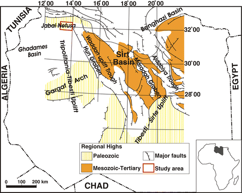
The study area () lies within the southernmost region of the city of Tarhunah in the northwestern part of Libya, bounded by longitudes 13°04′ E to 14°00′ E and latitudes 31°45′ N to 32°23′ N. It covers a surface area of approximately 6200 km2.
Figure 1. The study area, overlain on the tectonic map of Libya, modified from Rusk (Citation2001).
The study area has an elevation that ranges approximately between 300 and 900 m. Low topographic areas are covered mostly by fluvioeolian deposits, whereas most of the area is covered by basalt sheets, forming flat, broad plains.
The study area contains exposures of sedimentary rocks ranging in age from Middle and Late Triassic to Quaternary. The Aziziya Formation (Middle–Upper Triassic) is partially exposed in the northwestern part of the study area. The Abu Shaybah Formation (Upper Triassic) is present in the northwestern part of the study area and consists of sandstone alternating with bands of clays and scattered limy bands (Mann Citation1975). The Abu Ghaylan Formation (Upper Triassic–Middle Jurassic) appears as a narrow limestone ridge in the northwestern part of the study area (El Hinnawy and Cheshitev Citation1975).
The Sidi as Sid Formation (Cretaceous) is exposed through the northwestern part of the study area. It comprises two successive rock units, the Ain Tobi Limestone and Yafrin Marls (Mann Citation1975). The Nalut Formation (Cretaceous) is one of the most widely distributed rock units through the northern and northeastern parts of the study area. The Qasr Tigrinnah Formation (Cretaceous) is partly exposed in the western part of the study area. Jordi and Lonfat (Citation1963) included the Qasr Tigrinnah as a member of the Mizdah Formation (Upper Cretaceous), which is widely exposed in the southern part of the study area. As recognised by Jordi and Lonfat (Citation1963), the Mizdah Formation comprises three members, the Tigrinnah Marl, Mazuzah Limestone and Thala Member. El Hinnawy and Cheshitev (1975) restricted the Mizdah Formation to two members, the Mazuzah and Thala, and raised the Tigrinnah Marl to the status of a formation.
Volcanic rocks (Tertiary–Quaternary) are common in the central part of the study area. These volcanic rocks consist of three types: phonolite and trachyte intrusions, basalt cones and basalt flows. The phonolite and trachyte intrusions, partly observed in the northern part of the study area, exhibit topographic features of elevated, black, conical and some crater-shaped hills (Zivanovic Citation1977). Basalt cones are scattered over the basalt sheet in this area. They have a circular shape, with a raised rim, and invariably are intersected by lava extrusions (Antonovic Citation1977). The age of the basalt sheet was interpreted by Piccoli (Citation1971) as early Eocene to Pliocene, whereas the basalt at Wadi Ghan was interpreted by Christie (Citation1966) as early Quaternary.
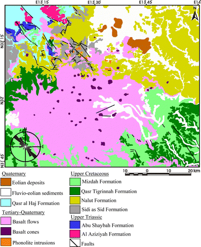
Quaternary sediments were observed throughout the study area, especially in the north. These Quaternary sediments were divided according to lithostratigraphic and genetic classification into four types: the Qasr Al Haj Formation (Pleistocene), fluvioeolian deposits (Holocene), eolian deposits (Holocene), and recent wadi deposits (Holocene) ().
Figure 2. Geological map of the study area and a rose diagram of surface faults (I.R.C., Citation1975a, Citationb, Citation1977a, Citationb) (Available in colour online).
At the end of the Cretaceous or in the early Tertiary the Gharyan-Tarhunah strip was uplifted and then formed an anticlinal swelling oriented NW–SE. According to Goudarzi (Citation1970), the main structural feature is a vast anticlinal swelling, the Gharyan-Yafran Arch, which trends NW–SE. In reference to Klitzsch (Citation1971), the uplift may have taken place in the third period of structural development in North Africa, the time (late Paleozoic and Mesozoic) when grabens and mountain ranges, oriented mostly NE–SW, began to form, and block faulting appeared along marginal parts of the uplifts (during the Jurassic or at the Triassic–Jurassic boundary). Burollet (Citation1963) assumed that Jabal Nefusa was uplifted during the Hercynian orogeny. The commonly accepted hypothesis is that the structural development of Jabal Nefusa was terminated toward the end of the Cretaceous (Mann Citation1975). Lipparini (Citation1940) believed that the uplift was accompanied by NW–SE faulting. All authors are in agreement as to the diminishing tectonic activity in the eastern part of Jabal Nefusa. The uplifted area that wedges out in the north could be regarded as disappearing uplifts buried by extensive volcanic flows (Gray Citation1971).
The E–W faults are recorded mainly from the subsurface and are represented by the Al Aziziyah and Coastal faults. The Aziziyah fault was active as a large right-lateral shear during the Atlas compressional phase and probably represents a basement feature (Burollet Citation1991, Tawadros Citation2001).
3. Data processing
A Landsat ETM+ image was processed and interpreted to identify geological features and produce a regional distribution of geological formations in the study area. The gravity data were used to validate the structures on the geological map and remotely sensed imagery from a point of potential field. Furthermore, the subsurface information for the geological structures can be retrieved from the gravity data. The three different data types were integrated for the distribution and depth information of the subsurface geological structures, using the geographic information system (GIS) technique.
3.1 Remote-sensing data
The main objective of the remote-sensing analysis was to extract and map lineaments. The ETM+ program was tested for identifying and mapping geological lineaments in the entire area. Filtering operations and PCA were used to improve the visual appearance of the satellite image and prepare the image for measurement of the features and structures. The extracting criteria for lineaments and visual interpretation were based mainly on the image characteristics (tone and texture), lithological boundaries (rock units) and the geomorphological features (drainage patterns).
Edge enhancement was performed by one of the two types of spatial filtering called a high-pass filter, which is designed to emphasise the detailed high-frequency components of an image and de-emphasise the more general low-frequency information (Lillesand and Kiefer Citation2000). Edge enhancement is performed by detecting edges and then either by adding these back into the original image to increase contrast in the vicinity of an edge or by highlighting edges using saturated (black, white or colour) overlays on borders (Richards Citation1993). An edge represents discontinuities or a sharp change in the grey-scale value of a particular pixel at a point that might have some interpretation in terms of geological structure or relief (Mather Citation1993). Directional gradient Prewitt and Sobel filters (Suzen and Toprak Citation1998, Gonzalez and Woods Citation2002, Mavrantza and Argialas Citation2002, Chanda and Majumdar Citation2003) were applied to the image in the four main directions—NW–SE, NE–SW, N–S and E–W—to emphasise spatial frequency and image contrast. The lineaments extracted and mapped from the Sobel and Prewitt filters are considerably different in number. From the analysis 207 lineaments were detected by the Sobel filter, whereas 173 lineaments were detected by the Prewitt filter. A comparison of the two maps indicates that most of the additional lineaments from the Sobel filter are short and inhomogeneous over the study area, with a mean lineament length of 1.4 km. The maximum lineament length is 4.8 km. However, the lengths of these lineaments are less than the expected values.
PCA allows the redistribution of data in the original channels by means of a linear transformation of channel variables between the same number of new channels in such a manner that the images in the first three principal component images must contain the most information in the N-band. The effectiveness of the PCA approach in identifying and analysing lineaments was investigated by Canas and Barnett (Citation1985), Qari (Citation1991), Leech et al. (Citation2003) and Won-In and Charusiri (Citation2003). Nama (Citation2004) argues that the lineaments can be easily identified by using PCA for the ETM+ image, which removes redundant information from visible and NIR multispectral data. The three first PCA bands were produced using all bands except the thermal and panchromatic bands (). The first three principal components contain 96.03% of the total variance of the ETM+ image. In all, 144 lineaments were extracted and mapped using PCA images. The total number of lineaments that were extracted and mapped by using the two remote-sensing techniques was 283. The mean length of all lineaments is 1.7 km, and the maximum length is approximately 6 km. All lineaments were compiled on a reinterpreted geological map on the basis of the ages of the geological formations ().
Figure 3. False-colour composite of PC1 (red), PC2 (green) and PC3 (blue). Dashed black lines indicate formation boundaries. Solid black lines indicate basalt cones. Solid yellow lines indicate phonolite intrusions.
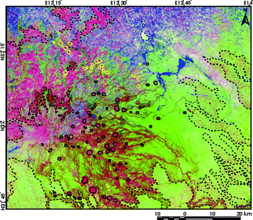
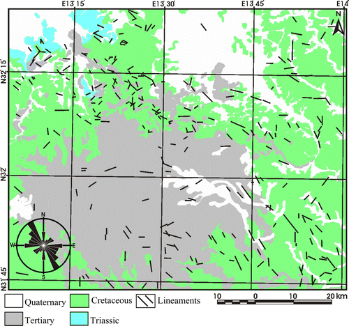
Figure 4. Geological formations by age, showing lineaments extracted from remote-sensing data. A rose diagram is also shown. (Available in colour online).
3.2 Gravity data
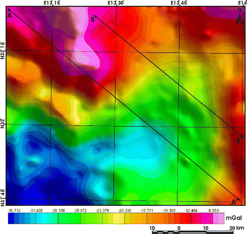
A gravity survey of the Tarhunah area was conducted in an attempt to delineate its subsurface structure. A density of 2,670 kg/m3 was used to compute a Bouguer anomaly map of this area. shows that the area is characterised by negative gravity values ranging between –36 and –8 mGal, increasing in value in the north-northwestern, northeastern, and eastern parts of the map area. These areas are composed mainly of limestone, dolomite and sandstone. It can be seen that the gravity map shows a graben system trending NE in association with the tectonic features of the area. In this study we have applied an upward-continuation filter with a distance of 500 m after examining the spectral analysis of the data and the results of the matched filter so as to reduce the effect of noise.
Figure 5. Gravity map of the study area (after upward continuation). (Available in colour online).
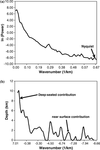
3.2.1 Energy spectrum analysis
A power spectral analysis yielded information on the depth of a significant density contrast in the crust and on the crustal structure (Kadirov Citation2000, Gotze and Krause Citation2002). Spector and Bhattacharyya (Citation1966) studied the energy spectrum, which was calculated from different 3-D model configurations. Then, Spector and Grant (Citation1970) studied the statistical ensemble of 3-D maps and concluded a general form of the spectrum
E: total energy (frequency Hz).
R: radial wave number (cycles/m).
θ: azimuth of radial wave number (degree).
〈〉: expresses ensemble average.
h: depth (meter).
H: depth factor.
S: horizontal size (width) factor.
C: vertical size (thickness or depth extent) factor.
a, b: parameters related to the horizontal dimensions of the sources.
t, Φ: parameters related to the vertical depth extent of the source.
It is clear that only three factors (H, S and C) are functions of the radial frequency r, thus in the case of profile form, equation (Equation7) can be written as
This equation demonstrates that contributions from the depths, widths and thicknesses of the source ensemble can affect the shape of the energy spectral decay curve.
(a) shows the energy power spectrum of the gravity data of the Tarhunah area. (b) shows the depths of the gravity sources. Two different gravity contributions can be seen: a deep-seated source at a depth of 10 km, and a shallow source at a depth of 2 km.
Figure 6. (a) Radially averaged power spectrum of the Bouguer anomalies of the study area; (b) gravity depth estimation based on linear segments of the energy decay curve.
3.2.2 Horizontal gradient technique
The horizontal gradient method has been used intensively to locate boundaries of density contrast from gravity or magnetic data (Ma et al. Citation2006, Bilim Citation2007, Pilkington Citation2007). Generally, the horizontal gradient of the gravity anomaly caused by a tabular body tends to overlie the edges of the body if the edges are vertical and isolated from each other (Cordell Citation1979, Cordell and Grauch Citation1985).
The best advantage of the horizontal gradient method is that it is least susceptible to noise in the data, because it only requires the calculations of the two first-order horizontal derivatives of the field (Phillips Citation1998). This method is also robust in delineating both shallow and deep sources, in comparison with the vertical gradient method, which is useful only in identifying shallower structures. The amplitude of the horizontal gradient (Cordell and Grauch Citation1985) is expressed as
Figure 7. Horizontal-gradient map of the upward-continued gravity data. Circles indicate the maxima of the horizontal gradient at which contacts could be located. These peaks are at the contacts or faults. In some places they are at the borders of the basin. (Available in colour online).
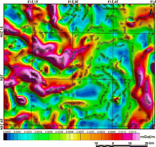
Once the horizontal-gradient map is obtained, the maximum peaks can be determined, using the criteria of Blakely and Simpson (Citation1986) shown as black circles in .
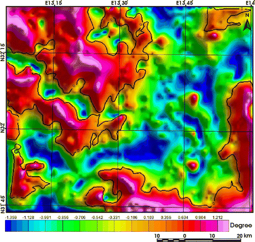
3.2.3 Tilt derivative (TDR) technique
The TDR is used to enhance and sharpen the potential field anomalies (Verduzco et al. Citation2004, Cooper and Cowan Citation2006). The advantage of the TDR is that its zero contour line is located on or close to the contacts. The operating definition (Miller and Singh Citation1994) is
The results of the TDR are presented in .
Figure 8. Tilt derivative of gravity data. Solid black line is the zero contour line, which matches well with the basin borders and also with the horizontal gradient map () of the gravity data. (Available in colour online).
3.2.4 Euler deconvolution technique
The Euler deconvolution technique is used to estimate depth and location of the magnetic gravity source anomalies. Euler deconvolution has come into wide use for automatic estimates of field source location and depth (Bournas et al. Citation2003, Shepherd et al. Citation2006, Chennouf et al. Citation2007, Li et al. Citation2008). This method was established by Thompson (Citation1982) and has been applied essentially to real magnetic data along profiles. Reid et al. (Citation1990) followed up a suggestion in Thompson's paper and developed the equivalent method, which operates on gridded magnetic data. The application of Euler deconvolution to gravity data has been carried out by several authors—e.g., Wilsher (Citation1987), Corner and Wilsher (Citation1989), Klingele et al. (Citation1991), Marson and Klingele (Citation1993), Fairhead et al. (Citation1994) and Huang et al. (Citation1995).
The 3-D equation of Euler deconvolution given by Reid et al. (Citation1990) is
By considering four or more neighbouring observations at a time (an operating window), source location (x o , y o , z o ) and β can be computed by solving a linear system of equations generated from Equation (Equation7). Then, by moving the operating window from one location to the next over the anomaly, multiple solutions for the same source are obtained. In our study the Euler method has been applied to the gravity data using a moving window of 0.01 km×0.01 km, and the grid cell size of the gravity data is 750 m. We have assigned several structural indices values and found that an SI of zero gives good clustering solutions. Reid et al. (Citation1990, Citation2003) and Reid (Citation2003) presented a structural index equal to zero for the gravity field for detecting faults. Results of the Euler deconvolution of gravity data are shown in .
Figure 9. Euler deconvolution of the upward continued gravity data (posted circles). The solutions of Euler are consistencies with the tilt derivative (TDR; zero contour line in black). At the zero contour line of the TDR, you can easily find the Euler solutions for faults/contacts. Background is image of gravity map.
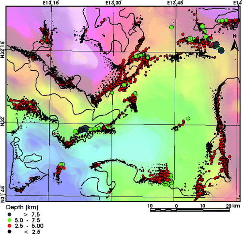
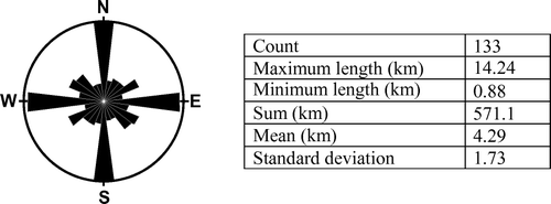
The interpretation of Euler solutions indicates that the NE–SW, NW–SE, E–W, and N–S trends characterise the structural setting of the Tarhunah area. The depth of faults ranges from 2.5 to 7.5 km. These contacts were interpreted as faults and plotted and statistically analysed (). The rose diagram () indicates that four major fault patterns (N–S, E–W, NE–SW, NW–SE) characterise the study area.
Figure 10. Rose diagram of faults extracted from gravity data.
3.2.5 Two-dimensional (2-D) forward modelling
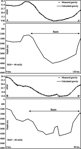
For quantitative gravity interpretation, a 2-D forward modelling method (Talwani et al. Citation1959) was applied to the gravity data. Two profiles were selected (A–A′ and B–B′, ). Both profiles were extracted from the Bouguer anomaly map to understand the subsurface structure and for identifying the borders of the basin and its depth. The density contrast between the two modelled layers is –0.2 g/cm3, as shown in . The density contrast is –0.2 g/cm3.
Figure 11. The 2-D forward gravity model, cross sections A–A′ and B–B′.
3.3 Data integration
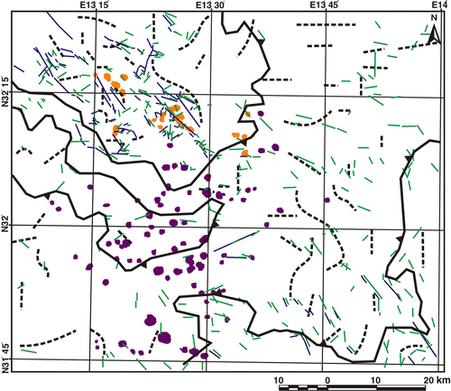
The GIS-based method was used to integrate raster and vector results extracted from geological field work, and remote-sensing and geophysical data analysis. The integrated analysis of the different data types was applied to find the mutual relationship as a base for geological analysis. The ultimate application of this technique should result in a more detailed and accurate geological interpretation. In particular, the integration of such data makes it possible to define both the relations of geological formations with the structural context (Rowland and Duebendorfer Citation1994), and provide new opportunities for studying the tectonic evolution of the study area ().
Figure 12. Basin trending NE. The estimated depth of faults ranges from 2.5 to 7.5 km. The borders of the basin are in black solid lines, based on the results of horizontal gradient, tilt derivative and Euler deconvolution. Dashed black lines indicate the interpreted faults from gravity data. Solid blue lines are the faults from the geological map. Solid green lines are the lineaments from the satellite image. Violet spots are basalt cones, and orange spots are phonolite intrusions. (Available in colour online).
4. Results
In accordance with the geological maps, the study area is mostly overlain by a basalt flow, with scattered basalt cones and phonolite intrusions. The faults trend predominantly NW–SE, whereas the E–W faults are subordinate. The NE–SW and N–S trends are not primary. A dominant NW–SE fault trend is evident in Triassic rocks. In Cretaceous rocks the dominant fault trend is NW–SE, with a subordinate E–W trend. Faults in Tertiary rocks are oriented predominantly NW–SE. In Quaternary sediments the predominant fault trend is NW–SE. In the Triassic and Cretaceous rocks the frequency and lengths of the NW–SE faults indicate reactivated faulting.
Lineaments extracted from remote-sensing data revealed different trends, but the main trend is NW–SE, parallel to the main tectonic line of the Jabal Uplift. The E–W lineaments represent a secondary trend. Other significant directions are N–S and NE–SW. The N–S trend is more conspicuous. The remaining directions are statistically unimportant. Variations in lineament trends can be explained by gentle anticlinal or broad synclinal forms. Lineaments extracted from remote-sensing data were divided into four groups, based on the age of the geological formations. Lineaments in Triassic rocks are dominantly NW–SE, whereas NE–SW is the subordinate direction. The prevailing trend of Cretaceous rock lineaments is NW–SE, and the second dominant trend is NE–SW. Lineaments of Tertiary rocks dominate in an E–W direction, with the NW–SE direction being subordinate. Quaternary sedimentary lineaments trend dominantly NW–SE and are the longest lineaments in these sediments.
Reconnaissance investigations and study of gravity data revealed a NE–trending basin with a width of 39 to 48 km. Faults extracted from horizontal gradient, tilt derivative, and Euler deconvolution methods show a dominant N–S trend with subordinate E–W faults. The depths of these faults range from 2.5 to 7.5 km. According to the gravity data and 2-D models, the basin gradually deepens toward the southwest. The faults extracted from gravity data can be placed into four groups. The first group (N–S) is most common in the eastern part of the area and represents the dominant trend. The second group (E–W) is a subordinate fault trend, based on gravity data. These faults are far apart and are about 5 km long. The third group trends NE–SW and is mostly along the edges of the basin, particularly on the west. The fourth group (NW–SE) is common in the northwestern part of the study area. These faults are relatively closely spaced and are about 6 km long. Generally, the two fault systems that trend NE–SW and NW–SE are far less common in comparison with faults of N–S and E–W trends. The depths of faults obtained from gravity data are shallow (<2.5 to >7.5 km deep). More analytically, the NW–SE faults appear mostly to be less than 2.5 km deep, whereas the NE–SW faults vary in depth from 2.5 to 7.5 km. The depths of the N–S faults range from less than 2.5 to 5 km. The E–W faults vary in depth between 2.5 and 7.5 km. Notably, the basalt sheet covers approximately 50% of the study area, although it disappears on the gravity map, this can indicate a thin, shallow basalt sheet.
5. Discussion and conclusion
The Gharyan-Tarhuna strip was uplifted during the end of the Cretaceous or the early Tertiary. This uplift caused anticlinal swelling trending in the NW–SE direction. This movement was followed by parallel faults (NW–SE). Moreover, the study area is surrounded by two main faults and structures, the Aziziyah Fault (E–W) from the north and the Hun Graben faults (NW–SE) from the southeast. Therefore a complex structure is anticipated in the study area.
The integration of results shows that four lineament trends were recognised and mapped in the study area. The NW–SE trend probably represents the longitudinal lineaments associated with the NW–SE uplift that affected the area. The NE–SW trend was probably rejuvenated from the NNE–SSW lineaments associated with the Tibesti-Sirte Uplift, which is well developed in the Paleozoic rocks. Another idea, put forth by Klitzsch (Citation1971), was that this trend could be related to the third period of the structural development of North Africa. The E–W trend is mostly related to the Al Aziziyah and Coastal faults. Two ideas have been advanced as to the genesis of the N–S faults: (1) this trend was caused by the same tectonic activity that was responsible for the Jabal Uplift (conjugate faults). (2) This trend was caused by some unknown tectonic movement. The first conclusion seems more logical.
Lithologically, the arrangement of phonolite hills and basalt cones in parallel lines with the dominant fault trends (NW–SE) indicates that the volcanic activity is related to the tectonic activity of the Jabal Uplift ().
The study area was probably affected by three main movements: (1) the oldest movement (Tibesti-Sirte Uplift) began in the Late Silurian Caledonian orogeny, which initially defined the limits of the Paleozoic basins of Libya (Rusk Citation2001). This uplift was associated with and followed by parallel faults trending NE–SW. (2) The second movement, at the end of the Cretaceous or in the early Tertiary, was the uplift that resulted in the formation of an anticlinal swelling in a NW–SE direction. This movement was followed by parallel faulting and magmatic activities represented in the study area by intrusive and extrusive volcanic rocks. (3) The third movement was in the pre-Miocene, related to the Al Aziziyah and Coastal faults. From this movement the study area underwent E–W faulting.
Notes on contributors
Nureddin Saadi is a PhD candidate at Kyushu University (Japan). He received his BS degree in geology from the Al-fateh University in 1994, and his MS degree in remote sensing and image processing from Dundee University (UK) in 2003. His current research interests include data fusion, data integration, and geological investigations.
Essam Aboud is a doctor of engineering in exploration geophysics (Graduate School of Engineering, Kyushu University, Japan). Now he is a staff at the National Research Institute of Astronomy and Geophysics (NRIAG), Helwan, Cairo, Egypt. His research interests include potential-fields (gravity and magnetic).
Hakim Saibi is a doctor of engineering in geothermics at the Department of Earth Resources Engineering, Kyushu University, Japan and currently a JSPS Post-doctoral fellow at the same university. His research interests include geothermal engineering (geothermal reservoir simulation), hydrogeology, hydrochemistry and geodesy (gravity and GPS). His particular research interest is the monitoring of gravity change at geothermal areas using relative and absolute gravimeters. Now, he is developing gravity post-processor for a computer simulation model.
Koichiro Watanabe is a professor at the Faculty of Engineering, Kyushu University, Japan. He is the head of the Laboratory of Economic Geology. His research interest is petrological monitoring system for active volcanoes. The major aim is to progress the technologies of geological exploration, including modern geochronology, isotope geology and geological modelling.
Acknowledgements
The authors are grateful to the Editor and three anonymous referees for their comments and suggestions to improve this paper.
References
- Antonovic , A. 1977 . Geological map of Libya. Explanatory booklet, sheet Mizdah NH 33-1 , Industrial Research Centre, Tripoli .
- Ayala , C. , Torne , M. and Pous , J. 2003 . The lithosphere–asthenosphere boundary in the western Mediteranean from 3D joint gravity and geoid modeling: tectonic implications . Earth and Planetary Science Letters , 209 : 275 – 290 .
- Bilim , F. 2007 . Investigations into the tectonic lineaments and thermal structure of Kutahya-Denizli region, western Anatolia, from using aeromagnetic, gravity and seismological data . Physics of the Earth and Planetary Interiors , 165 ( 3-4 ) : 135 – 146 .
- Blakely , R.J. and Simpson , R.W. 1986 . Locating edges of source bodies from magnetic and gravity anomalies . Geophysics , 51 ( 7 ) : 1494 – 1498 .
- Bonham-Carter , G.F. 1989 . Comparison of images analysis and GIS for integration geosciences maps . Geological Survey of Canada , S9–9 : 141 – 155 .
- Bournas , N. , Galdeano , A. , Hamoudi , M. and Baker , H. 2003 . Interpretation of the aeromagnetic map of Eastern Hoggar (Algeria) using the Euler deconvolution, analytic signal and local wavenumber methods . Journal of African Earth Sciences , 37 ( 3–4 ) : 191 – 205 .
- Burollet , P. F. 1963 . Excursion to Jabal Nefusa. Petroleum Exploration Society Libya , Tripoli .
- Burollet , P.F. 1991 . Structures and tectonics of Tunisia . Tectonophysics , 195 : 359 – 369 .
- Canas , A. A. D. and Barnett , M. E. 1985 . The generation and interpretation of false-colour composite principal component images . International Journal of Remote Sensing , 6 : 867 – 881 .
- Cengiz , O. , Sener , E. and Yagmurlu , F. 2006 . A satellite image approach to the study of lineaments, circular structures and regional geology in the Golcuk Crater district and its environs (Isparta, SW Turkey) . Journal of Asian Earth Sciences , 27 ( 2 ) : 155 – 163 .
- Chanda , B. and Dutta Majumdar , D. 2003 . Digital Image Processing and Analysis , New Delhi : Prentice-Hall of India .
- Chen , S. and Zhou , Y. 2005 . Classifying depth-layered geological structures on Landsat TM images by gravity data: A case study of the western slope of Songliao Basin, northeast China . International Journal of Remote Sensing , 26 : 2741 – 2754 .
- Chennouf , T. 2007 . Major structural trends in northeastern Morocco: The contribution of gravimetry . Comptes Rendus – Geoscience , 339 : 383 – 395 .
- Christie , A.M. 1966 . Geology of Gharyan Area, Tripolitania, Libya. Ministry of Industry, Geological Section Bulletin, No. 5 , Tripoli .
- Cooper , G.R.J. and Cowan , D.R. 2006 . Enhancing potential field data using filters based on the local phase . Computers and Geosciences , 32 : 1585 – 1591 .
- Cordell , L. 1979 . Gravimetric expression of graben faulting in Santa Fe Country and the Espanola Basin, New Mexico , Guidebook to the 30th Field Conference , Santa Fe Country, New Mexico Geological Society (Ed), New Mexico Geological Society, Socorro, 59–64.
- Cordell , L. and Grauch , V.J.S. 1985 . “ Mapping basement magnetization zones from aeromagnetic data in the San Juan Basin, New Mexico ” . In The utility of regional gravity and magnetic anomaly maps: Society of Exploration Geophysicists Edited by: W. J. Hinze , W.J. 181 – 197 .
- Corner , B. Wilsher , W.A 1989 Structure of the Witwatersrand basin derived from interpretation of the aeromagnetic and gravity data In G.D. Garland Proceedings of Exploration '87, Third Decennial International Conference on Geophysical and Geochemical Exploration for Minerals and Groundwater: Ontario Geological Survey. Special , 3 532 – 546
- El Hinnawy , M. and Cheshitev , G. 1975 . Geological map of Libya. Explanatory booklet, sheet Tarabulus NI 33–13 . Industrial Research Centre, Tripoli.
- Fairhead , J.D. , et al. 1994 . Euler: Beyond the Black Box . 64th Annual International Meeting, Society of Exploration Geophysicists , Expanded Abstracts , 422 – 424 .
- FitzGerald , D. , Reid , A. and McInerney , P. 2004 . New discrimination techniques for Euler Deconvolution . Computers & Geosciences , 30 : 461 – 469 .
- Fraser , A. 1997 . A satellite remote sensing technique for geological structure horizon mapping . International Journal of Remote Sensing , 18 : 1607 – 1615 .
- Gonzalez , R.C. and Woods , R.E. 2002 . Digital image processing, 2nd ed , Upper Saddle River, NJ : Prentice Hall .
- Gotze , H.-J. and Krause , S. 2002 . The Central Andean gravity high, a relic of an old subduction complex? . Journal of South American Earth Sciences , 14 : 799 – 811 .
- Goudarzi , G.H. 1970 . Geology and mineral resources of Libya – A reconnaissance . Geological Survey Professional Paper , 660 , 104 p, Washington , DC .
- Gray , C. 1971 . Structure and origin of the Garian Domes . Symposium on the Geology of Libya , University of Libya, 307–319, Tripoli 1971.
- Harris , J.R. 1991 . Mapping of regional structure of eastern Nova Scotia using remote sensing imagery: implication for regional tectonics and gold exploration . Canadian Journal of Remote Sensing , 17 : 122 – 135 .
- Huang , D. , et al. 1995 . Combined study of Euler's homogeneity equation for gravity and magnetic field . 57th Conference and Technical Exhibition EAGE, Glasgow , Extended Abstracts, P144 .
- Industrial Research Centre (I.R.C) , 1975a . Geological map of Libya, 1:250,000, sheet: Tarabulus , Tripoli-Libya .
- Industrial Research Centre (I.R.C) , 1975b . Geological map of Libya, 1:250,000, sheet: Al Khums , Tripoli-Libya .
- Industrial Research Centre (I.R.C) , 1977a . Geological map of Libya, 1:250,000, sheet: Mizdah , Tripoli-Libya .
- Industrial Research Centre (I.R.C) , 1977b . Geological map of Libya, 1:250,000, sheet: Bani Walid , Tripoli-Libya .
- Jordi , H. A. and Lonfat , F. 1963 . Stratigraphic subdivision and problems in Upper Cretaceous–Lower Tertiary deposits in Northwestern Libya. First Sahara Symposium, Tripoli. Revue de I . Institut Francais du Petrole , 18 ( 10 ) : 114 – 122 .
- Kadirov , F.A. 2000 . Application of the Hartley transform for interpretation of gravity anomalies in the Shamakhy-Gobustan and Absheron oil- and gas-bearing regions, Azerbaijan . Journal of Applied Geophysics , 45 ( 1 ) : 49 – 61 .
- Klingele , E. E. , Marson , I. and Kahle , H. G. 1991 . Automatic interpretation of gravity gradiometric data in two dimensions: vertical gradient . Geophysical Prospecting , 39 : 407 – 434 .
- Klitzsch , E. 1971 . The structural development of parts of North Africa since Cambrian time. Symposium on the geology of Libya, faculty of science , University of Libya, Tripoli, Libya .
- Lamontagne , M. , Keating , P. and Perreault , S. 2003 . Seismotectonic characteristics of the lower St. Lawrence seismic zone, Quebec: insights from geology, magnetics, gravity, and seismics . Canadian Journal of Earth Sciences , 40 : 317 – 336 .
- Leech , D.P. 2003 . Landsat TM analysis of fracture patterns: a case study from the Coastal Cordillera of northern Chile . International Journal of Remote Sensing , 24 : 3709 – 3726 .
- Li , C.-F. 2008 . Late Mesozoic tectonic structure and evolution along the present-day northeastern South China Sea continental margin . Journal of Asian Earth Sciences , 31 ( 4–6 ) : 546 – 561 .
- Lillesand , T.M. and Kiefer , R.W. 2000 . Remote sensing and image interpretation , 4th edn , New York : John Wiley .
- Lipparini , T. 1940 . Tettonica e geomorfologia della Tripolitania. Bulletin of the Geological Society of Italy . Roma , 59 : 221 – 301 .
- Lunden , B. , Wang , G. and Wester , K. 2001 . A GIS based analysis of data from Landsat TM, airborne geophysical measurements, and digital maps for geological remote sensing in the Stockholm region, Sweden . International Journal of Remote Sensing , 22 : 517 – 532 .
- Ma , Z.-J. , Gao , X.-L. and Song , Z.-F. 2006 . Analysis and tectonic interpretation to the horizontal-gradient map calculated from Bouguer gravity data in the China mainland . Chinese Journal of Geophysics (Acta Geophysica Sinica) , 49 ( 1 ) : 106 – 114 .
- Mann , K. 1975 . Geological map of Libya. Explanatory booklet, sheet Al Khums 33–14 , Industrial Research Centre, Tripoli .
- Marson , I. and Klingele , E.E. 1993 . Advantages of using the vertical gradient of gravity for 3-D interpretation . Geophysics , 58 : 1588 – 1595 .
- Mather , P. M. 1993 . Computer processing of remotely sensed images , Chichester. New York. Brisbane. Toronto. Singapore : John Wiley & Sons .
- Mavrantza , O.D. and Argialas , D.P. 2002 . Implementation and evaluation of spatial filtering and edge detection techniques for lineament mapping-Case study: Alevrada, Central Greece . Proceedings of SPIE – The International Society for Optical Engineering , 4886 : 417 – 428 .
- Miller , H. G. and Singh , V. 1994 . Potential field tilt – a new concept for location potential field sources . Applied Geophysics , 32 : 213 – 217 .
- Nama , E.E. 2004 . Lineament detection on Mount Cameroon during the 1999 volcanic eruptions using Landsat ETM . International Journal of Remote Sensing , 25 : 501 – 510 .
- Pereira A.J.S.C. , et al. , 2008 . Structural lineaments in a volcanic island evaluated through remote sensing techniques . International Geoscience and Remote Sensing Symposium (IGARSS) , art. No. 4423127, 1632–1635 .
- Phillips , J.D. 1998 . Processing and interpretation of aeromagnetic data for the Santa Cruz Basin-Patahonia Mountains area, South-Central Arizona . U. S. Geological Survey Open-File Report 02-98 .
- Piccoli , G. 1971 . “Outlines of Volcanism in Northern Tripolitania. Symposium on the Geology of Libya” , University of Libya , 232 – 331 , Tripoli 1971 .
- Pilkington , M. 2007 . Locating geologic contacts with magnitude transforms of magnetic data . Journal of Applied Geophysics , 63 ( 2 ) : 80 – 89 .
- Qari , M.Y.H.T. 1991 . Application of Landsat TM Data to Geological Studies, Al-Khabt Area, Southern Arabian . Photogrammetric Engineering and Remote Sensing , 57 : 421 – 429 .
- Raharimahefa , T. and Kusky , T.M. 2006 . Structural and remote sensing studies of the southern Betsimisaraka Suture, Madagascar . Gondwana Research , 10 ( 1–2 ) : 186 – 197 .
- Reid , A.B. 1990 . Magnetic interpretation in three dimensions using Euler Deconvolution . Geophysics , 55 : 80 – 91 .
- Reid , A.B. , FitzGerald , D. and McInerney , P. 2003 . Euler Deconvolution of gravity data. Society of Exploration Geophysicists (SEG) . Annual Meeting , 2003 : 580 – 583 .
- Reid , A.B. 2003 . Short note: Euler magnetic structural index of a thin-bed fault . Geophysics , 68 : 1255 – 1256 .
- Richards , J. A. 1993 . Remote sensing digital image analysis, An introduction, second edition , Berlin : Springer-Verlag .
- Rowland , S.M. and Duebendorfer , E.M. 1994 . Structural analysis and synthesis: Second Edition , Palo Alto : Blackwell Scientific Publications .
- Rusk , D.C. 2001 . “ Libya: Petroleum potential of the under explored basin centers: A twenty-first century challenge ” . In Petroleum provinces of the twenty-first century: AAPG Memoir Edited by: Downey , M.W. , Threet , J. C. and Morgan , W. A. 429 – 452 .
- Shepherd , T. , Bamber , J.L. and Ferraccioli , F. 2006 . Subglacial geology in Coats Land, East Antarctica, revealed by airborne magnetics and radar sounding . Earth and Planetary Science Letters , 244 ( 1-2 ) : 323 – 335 .
- Spector , A. and Bhattacharyya , B.K. 1966 . Energy density spectrum and autocorrelation function of anomalies due to simple magnetic models . Geophysical Prospecting , 14 : 242 – 272 .
- Spector , A. and Grant , F.E. 1970 . Statistical models for interpreting aeromagnetic data . Geophysics , 35 : 293 – 302 .
- Suzen , M. L. and Toprak , V. 1998 . Filtering of satellite images in geological lineament analyses: an application to a fault zone in Central Turkey . International Journal of Remote Sensing , 19 : 1101 – 1114 .
- Talwani , M. , Worzel , J.L. and Landisman , M. 1959 . Rapid gravity computations for two-dimensional bodies with applications to the Mendocino submarine fracture zone . Journal of Geophysical Research , 64 : 49 – 59 .
- Tašárová , Z.A. 2007 . Towards understanding the lithospheric structure of the southern Chilean subduction zone (36°S–42°S) and its role in the gravity field . Geophysical Journal International , 170 ( 3 ) : 995 – 1014 .
- Tawadros , E. 2001 . Geology of Egypt and Libya , Rotterdam : A. A. Balkema .
- Thompson , D. T. 1982 . EULDPH – A new technique for making computer-assisted depth estimates from magnetic data . Geophysics , 47 : 31 – 37 .
- Verduzco , B. 2004 . New insights into magnetic derivatives for structural mapping . Leading Edge (Tulsa, OK) , 23 ( 2 ) : 116 – 119 .
- Wilsher , W. A. 1987 . A structural interpretation of the Witwatersrand basin through the application of the automated depth algorithms to both gravity and aeromagnetic data . Thesis (MSc). University of Witwatersrand .
- Won-In , K. and Charusiri , P. 2003 . Enhancement of thematic mapper satellite images for geological mapping of the Cho Dien area, Northern Vietnam . International Journal of Applied Earth Observation and Geoinformation , 15 : 1 – 11 .
- Yassaghi , A. 2006 . Integration of Landsat imagery interpretation and geomagentic data on verification of deep-seated transverse fault lineaments in SE Zagros, Iran . International Journal of Remote Sensing , 27 : 4529 – 4544 .
- Yegorova , T.P. 2004 . Structure of the lithosphere below the southern margin of the East European Craton (Ukraine Russia) from gravity and seismic data . Tectonophysics , 381 : 81 – 100 .
- Zeinalov , G.A. 2000 . Importance of remote-sensing data in structural geologic analysis of oil- and gas-bearing regions of Azerbaijan . Natural Resources Research , 9 : 307 – 313 .
- Zivanovic , M. 1977 . Geological map of Libya. Explanatory booklet, sheet Bani Walid NH 33-2 , Industrial Research Centre, Tripoli .