
Abstract
Remotely sensed Digital Elevation Models (DEM) can be used to augment a standalone Global Positioning System (GPS) by adding an extra range observation which measures the distance to the Earth centre. This method so called height aiding can reduce the number of GPS satellites required to get a 3D position fix from four to three and hence improve the performance of the GPS navigation algorithm in terms of accuracy, reliability and availability. Up until now, the accuracy of height aided GPS navigation using higher resolution Synthetic Aperture Radar (SAR) and Light Detection and Ranging (LiDAR)-derived elevation data has not been fully evaluated in a broad spectrum of navigation scenarios. This article provides a robust and accurate analysis on how much range error is introduced by height aiding using 5 m spacing SAR and 1 m spacing LiDAR-derived DEMs under in-car and personal navigation situations. Based on the experimental results obtained from both dynamic and static tests, suggestions have been made on what level of vertical and positional accuracy can be achieved as well as the related DEM quality issues for navigation purposes.
Keywords:
1. Introduction
Global Positioning System (GPS) as a key component of Digital Earth can pinpoint a user's position anywhere anytime on the Earth surface. In recent years, the amount and coverage of remotely sensed Digital Elevation Models (DEM) data at higher resolution and accuracy have been on the increase due to the technological advances and efficiency improvement in Synthetic Aperture Radar (SAR) and Light Detection and Ranging (LiDAR) instrument. Such remotely sensed data at 1 m or even higher resolution provides an opportunity to further enhance and improve the accuracy and reliability of GPS which has been widely used in various Earth-oriented applications such as in (Yildirim Citation2013) and (Ajmar et al. Citation2013) within the geographic information system (GIS) and remote sensing community. Up until now, the use of SAR and LiDAR DEM for augmenting a single GPS receiver for personal and in-car navigation has not been fully evaluated and there is a lack of reliable experimental results under a broad spectrum of navigation scenarios. In order to evaluate what level of vertical and positional accuracy can be achieved as well as the causes of errors and related DEM quality issues, a comprehensive experiment needs to be carried out to provide more reliable and useful scientific evidence to the field.
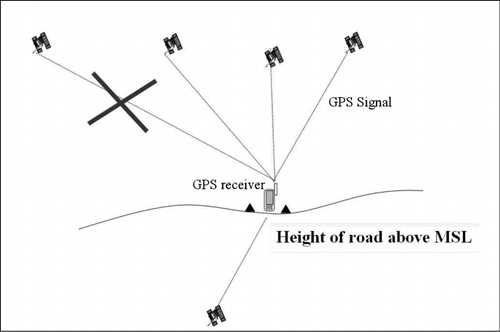
As illustrated in , height values interpolated from a DEM can be converted to a range measurement related to distance to the centre of the Earth and the Earth centre in this case can be treated as an additional GPS satellite or a pseudo-satellite (see ). In contrast to the distance measurement to the GPS satellites taken by the GPS receiver (i.e. pseudorange measurement), this particular range measurement (i.e. distance to the Earth centre) is relatively stable and only sensitive to the elevation change regardless of the movement in x and y on the Earth surface. Making use of this method and DEM data, only three GPS satellites are required to get a 3D position fix instead of four satellites (i.e. the minimum number of GPS satellites required for positioning service availability is reduced to three from four). This technique so called height aided GPS or height aiding is particularly useful and effective in the areas where GPS satellite availability is low (e.g. GPS signal masking due to trees or large obstructions) or GPS satellite-receiver geometry is poor. It is known that the vertical accuracy of a single GPS receiver without augmentation is usually two times worse than the horizontal accuracy and therefore unsuitable for the purpose of height aiding. Furthermore, the height interpolated from a higher resolution DEM is expected to be more accurate and useable than that output by a standalone GPS receiver.
The theory of height aided GPS was reviewed and presented in the literature such as in Jwo (Citation2001) and Stein (Citation1985). To date, very little research and experiments have been conducted on the use of higher resolution SAR and LiDAR derived DEMs for aiding GPS under various navigation conditions. The full potential and the achievable accuracy provided by height aided GPS with higher resolution DEMs have not been fully evaluated. Mandel and Laue (Citation2010) presented particle filter-based position estimation in road networks using DEMs. In their work, 90 m resolution SRTM DEM with an absolute vertical accuracy of 16 m is used, which brought an average positioning accuracy improvement of around 0.6 m and 7 m in two test runs, respectively. Li, Taylor, and Kidner (Citation2005) used 10 m and 50 m resolution contour-derived DEMs to aid a single GPS receiver and proved that the interpolated heights from these two DEMs are more accurate than the raw heights output directly by a single GPS receiver. Dumble and Gibbens (Citation2014) presented a optimization method which correlated the measured terrain information with a Digital Terrain Model to estimate the position and attitude of the vehicle. Ali et al. (Citation2012) used LiDAR sensor to estimate GPS multipath error.
Following previous research in (Li and Jarvis Citation2009) which made an initial attempt to examine the accuracy improvement provided by height aiding using multi-resolution DEMs, the contribution of this paper is to provide a comprehensive analysis of how much range error (i.e. error in measured distance to the Earth centre) can be introduced particularly by height aiding using newly acquired 5 m SAR and 1 m resolution LiDAR DEM under various navigation environments as well as the achievable positioning accuracy and relevant DEM quality issues.
2. Methodology
The mathematical model of GPS have been well documented in the literature such as in Blewitt (Citation1997) and Langley (Citation1991). A short description is given here. In principle, all GPS positions are computed by measuring the distance from the GPS satellites to the receiver on the Earth. These distances are often termed pseduoranges, as the measured distances contain a multitude of sources of error (e.g. multipath and atmospheric errors).
The approach adopted in this work is to extend and modify the mathematical model for single point positioning to incorporate the extra height measurement from a DEM. As a result, the system of pseduorange equations for three satellites in view augmented by the height aiding Equation (4; i.e. distance to the Earth centre) is obtained as follows:
c is the speed of light. The receiver position (x, y, z) and the receiver clock bias τ are the four unknowns to be determined. Note that for simplicity only three satellites are listed above but in real conditions there may be more than three satellites involved in the position computation, in which case the number of equations expand to the number of visible satellites forming a over-determined system of observation equations.
In the case of height aiding using a DEM, p4 in Equation (4) is the distance to the Earth centre which can be considered as a pseudo-satellite located at (0, 0, 0,) in WGS84 coordinate system as described in .
The point positioning problem is solved by first linearising the system of Equation (1)–(4) and then using the popular method of least-squares solution. The solution to the linearised form of the observation equations is given by:
It can be seen that height aiding provides one extra measurement to add redundancy to the computation of positioning and therefore has the potential to increase the availability, reliability and accuracy of a standalone GPS receiver especially when the number of visible satellites is low or the satellite-receiver geometry is poor.
In this research, the elevation of the x, y position at the previous epoch (i.e. second) is bilinearly interpolated from the DEM data and then transformed to the distance to the Earth centre to be used in the position computation at the current epoch. It should be noted that this method has a limitation in that the accuracy of the distance to the Earth centre for the current position depends on the height quality of the previous position fix which means that the range measurement error introduced by height aiding gets larger as the height difference between the current and previous epoch becomes larger. Consequently, this method works best in flat areas or the areas with varying slopes where the height difference between two adjacent points is not significantly large. Since the positions of the two adjacent epochs are usually close to each other in distance and height, this assumption generally holds for the applications in which no abrupt height change between two consecutive points appear. Although this limitation can be mitigated by a more robust search or a filtering algorithm to a smaller or larger extent, this research aims to precisely quantify the range error introduced by the height aiding approach in its original form without any further processing in order to provide reliable experimental results and useful insights into the achievable height aided GPS accuracy for the interested researchers.
Moreover, If GPS is unavailable due to obstructions for a period of time, the last previous position fix could be far away from the current position, in which case the last previous position is discarded and a more up-to-date height is interpolated at the current position for the use of height aiding at next epoch ever since GPS becomes online again.
3. Experimental set-up and data
GPS coordinates output from a single GPS receiver was collected in a vehicle driven on a road segment of around 2 km in length and 3.4 m–4.4 m in width. The data from this moving receiver can be either augmented by height aiding or without any augmentation. Simultaneously, dual frequency GPS phase data observations were collected in the vehicle and also by a static receiver recording base station data, on the roof of a nearby building. This phase data were used to compute a high precision (centimetre accuracy) Real Time Kinematic (RTK) GPS solution, which was assumed to be the ‘true’ position of the vehicle at each epoch (one second). The accuracy of the RTK solution (Leica Citation1999) is 1–2cm in plan and 2–4cm in height.
The position error is computed as the 2D distance between the RTK position and the corresponding height aided GPS position collected at the same epoch.
The error in distance to the Earth centre is obtained by subtracting the 3D distance between the RTK position and the Earth centre at the current epoch from the 3D distance between the height aided GPS position and the Earth centre at the previous epoch in WGS84 coordinate reference frame. This range measurement can be used to replace a pseudorange measurement from a GPS satellite (see Equation 4).
The terrain data includes 1 m spacing airborne LiDAR-derived Digital Surface Model (DSM) with a vertical accuracy of around 15 cm (i.e. DSM contains vegetation and buildings), 5 m spacing NextMap SAR-derived DSM acquired by airborne Interferometric Synthetic Aperture Radar technology with a documented vertical accuracy of around 0.5 m and 10 m spacing contour-derived bare-earth DEM from national mapping agency. In addition to the DEM data, accurate road-centre line data at 1 m accuracy level from national mapping agency was also used in the experiment. The terrain models used in this work are based on the map coordinates (i.e. the projected coordinates), user positions must be transformed from WGS84 to the projected coordinates and vice versa. To achieve a better transformation accuracy, the National Grid Transformation and Geoid Model were used to convert WGS84 3D Cartesian coordinates to easting, northing and orthometric height (i.e. the height above mean sea level) and vice versa. This process of itself improves the horizontal transformation accuracy from 0.2 m to 0.1 m RMS and the vertical accuracy from 0.05 m to 0.02 m RMS in comparison with the previous models (Ordnance Survey Citation2005).
4. Road test
4.1. Accuracy analysis
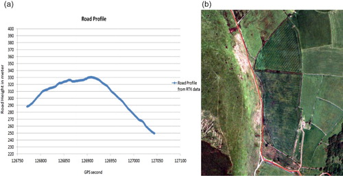
In the road test, a pair of geodetic grade Leica receiver was used. The moving receiver is mounted on top of a car driving at a average speed of 30 km per hour along a road segment of around 2 km long in an rural area as shown in . The base station was established at a known location in close proximity to the moving receiver (within 5 km). The combined RTK solution from the base and the moving receiver provides a reference trajectory at centimetre level accuracy. The road height profile reconstructed from a total of processed 274 RTK points is shown in . It can seen from that the road profile gently goes up until around epoch 126900 and then goes down more sharply towards the end of the journey. It should be noted that the driving speed does influence the range error caused by height aiding as the change of slope between two adjacent positions depends on the driving speed and the slope of the road. Having examined elevation change between consecutive points from the RTK data, the expected error for the car driving at 90 km per hour in the measured distance to the Earth centre is between 1 m and 3 m. Slower speed will lower the error budget to 1 m or even less.
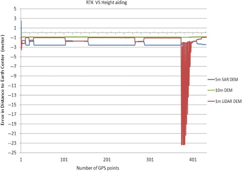
clearly demonstrates a comparison in the error in distance to the Earth centre (calculated as described in Section 3) introduced specifically by height aiding using 1 m, 5 m and 10 m elevation data, respectively when only three GPS satellites are available. Note that given three satellites in view, a 3D position fix is not available without height aiding and thus height aiding improve the availability of the positioning service in this situation.
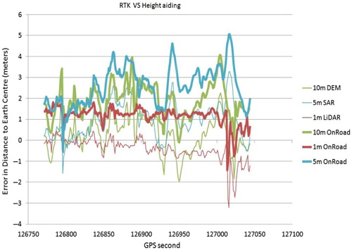
In order to investigate the spatial uncertainty introduced by height aiding, the height of the vertices at 1 m interval on the road centre line data is interpolated from 1 m, 5 m and 10 m DEM, respectively and used by first snapping raw GPS coordinates onto the road and then bilinearly interpolating the height of the GPS points between the two nearest road vertices (i.e. ‘onroad’ as shown in ). Snapping GPS coordinates onto the road is expected to reduce the possible large elevation error caused by cross track error on the basis that the testing car always travels on the road.
It is quite clear from that the error in measured distance to the Earth centre (i.e. height) introduced by the 1 m LiDAR data represented in light red line is very small (between 1 m and –1 m most of the time), which turns out to be a very effective and accurate measurement and even more accurate than the range measurement from the GPS satellite. Such range (height) accuracy at 1 m to 2 m level provided by height aided GPS with LiDAR data can effectively enhance the navigation performance of a single GPS receiver in terms of accuracy, reliability and availability especially in built-up areas where satellite visibility and geometry are likely to become low. In addition, the overall trend in error increases slowly towards –1 m due to the change in driving speed and deeper road slope along the second half of the road shown in .
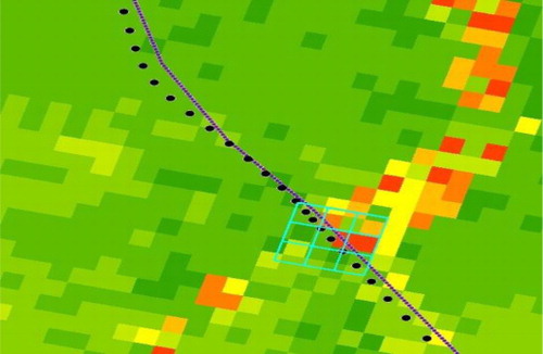
An apparent large range error up to –3 m provided by 1 m LiDAR data at epoch 127016 in is caused by a deep slope of around 63° crossing the road as displayed in which suggests that man-made or natural surface features and vegetation contained in finer resolution DSM may interfere with interpolating the correct height in transport applications. A filtered bare-earth DEM can be more suitable depending on the application at hand.
also demonstrates that the error in distance to the Earth centre provided by 5 m SAR and 10 m DEM is less stable and has larger and more fluctuations compared with that of 1 m LiDAR data. The magnitude of the error introduced by 5 m SAR and 10 m DEM is between 5 m and –3 m which is larger than that of LiDAR data (1 m and –3 m) as less surface details can be adequately modelled in the coarser resolution DEM data.
Matching computed positions on to road and then interpolating are supposed to reduce the spatial uncertainty at the location where the height is interpolated. The thicker lines named ‘onroad’ in show the error after snapping GPS points onto the road and interpolation with three types of elevation data, respectively. For 1 m LiDAR data, the error provided by ‘on road’ in is larger and shifted to around 1 m compared with an error of around 0 m without map-matching. This gives us an estimate of error uncertainty in the height aiding computation because various errors from both GPS satellites and DEM can change the coordinates of the interpolation location. Again, map-matching with 5 m SAR and 10 m DEM do not perform as accurate as that of 1 m LiDAR DSM.
Having investigated the individual range error incurred by height aiding in , shows the final position error in plan computed from both height aiding plus three GPS satellites in view. Since there are only three GPS satellites plus height aiding, the effect of height aiding on the position determination is more dominant and makes more significant contribution to the overall position accuracy when comparing with the solution from more than four satellites in view.
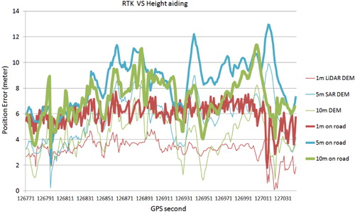
It can be clearly seen that a few metre error in height in can result in larger position errors as seen in . For example, a height error of 5 m at 127025 in can produce a position error of 13 m with the same set of satellites in .
The general trend of position error in is similar to that of the range error in , but fluctuates at a larger magnitude between 0 m and 13 m in plan in contrast to a magnitude between –3 m and 5 m in height. Moreover, it should be noted that the position accuracy not only depends on the range measurement by height aiding but a combined solution with the other three pseudorange measurements from the GPS satellites and the least squares computation. Since the errors in these range measurements vary from time to time, provides a reference as to what level of positioning accuracy can be achieved when using different types of DEM for height aiding plus a minimum of three GPS satellites for personal and in-car navigation.
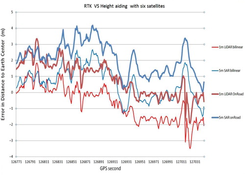
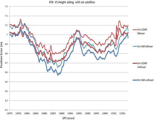
Following the study on the results from a minimum of three satellites plus height aiding, and show the height and position accuracy when there are six GPS satellites in view plus height aiding. In practice, six satellites provide three more redundant range measurements and therefore lead to better averaging in the least squares computation. As seen from and , a range of height errors between –3 m and 4 m in only result in a range of position errors between 6.6 m and 7.1 m (i.e. less than 1 m), which indicate that height aiding has very little influence on the combined position accuracy computed with six satellites regardless of the types of DEMs used in the experiment. This is expected as height aiding in this situation is only one of the seven measurements and therefore less dominant on the overall position solution. Furthermore, six satellites provide a more consistent and stable position accuracy (6–7 m accuracy consistently) compared with that of three satellites plus height aiding.
4.2. Augmented satellite receiver geometry
Apart from enhanced positioning accuracy and availability, height aiding can also improve the satellite-receiver geometry which is a key indicator of position accuracy. Position Dilution of Precision (PDOP) is commonly used to assess the strength of satellite-receiver geometry in relation to positioning accuracy. In theory, DOP values are a function of the diagonal elements of the covariance matrix (AτA)−1 in the equation 5. Position DOP is therefore given by:
5. Static test
5.1. Static test under weak signal environments
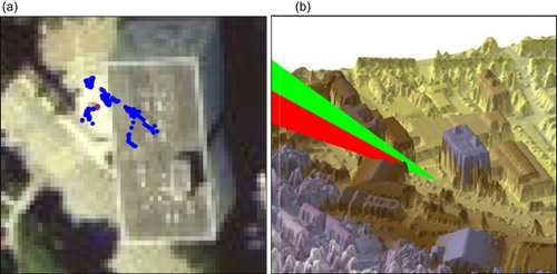
In addition to the dynamic test described above, a static test is carried out on the university campus in Wales at a known location. A novel 3D visualisation method is developed to capture large position errors caused by nearby buildings and subsequent large interpolated height errors using 3D LiDAR DSM and satellite orbit data. It is well known that GPS signals suffer from signal masking from nearby buildings or vegetation. Due to the high resolution and 3D detail in LiDAR data, LiDAR DSM can be used to model when and where a particular set of GPS satellites can be obstructed by nearby buildings (Li et al. Citation2008; Li, Jarvis, and Brunsdon Citation2010; Bauer, Obst, and Wanielik Citation2012). To achieve this, the line of sight analysis needs to be performed constantly in real time between the moving GPS satellites and the receiver over the 1 m LiDAR terrain model as shown in . demonstrate that the satellite visibility simulation is being run in a 3D virtual reality environment in which a particular satellite, being masked and unmasked by a building roof over a period of two minutes, is identified as an error source for interpolating height. As shown in , the red point is the true receiver position surveyed by RTK GPS at centimetre accuracy. The surrounding environment of this point contains a few stairs and some small man-made objects on top of gently undulating terrain as well as a nearby tall building. In the static test, the receiver is held static, the blue points are the height aided GPS coordinates scattered around the true position computed over a period of 440 seconds during which a few points fall on top of a 23 m high building on the campus resulting in large interpolated height errors from LiDAR data. As shown in , 5 m SAR data provides the worst range accuracy (around –3 m), both 10 m DEM and 1 m LiDAR DSM perform well and provide a range error of around –1 m most of the time except that at a few epochs the range error of up to –23 m provided by LiDAR DSM is caused by a satellite being partially masked and unmasked by a nearby building edge, as visualised in (i.e. signal diffraction can introduce large range error into positioning) resulting in a 13 m position error away from the true position and subsequent large interpolation errors on top of the nearby tall building.
This phenomena suggests that a filtered bare-earth LiDAR DEM could be used for personal navigation to avoid abrupt changes in elevation.
5.2. Height aiding error simulation
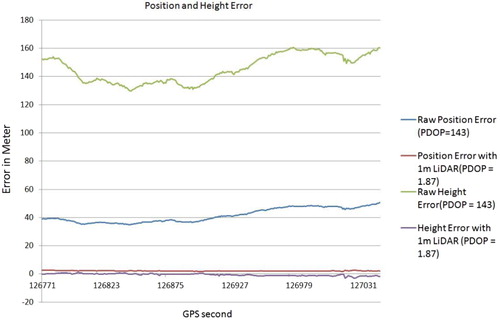
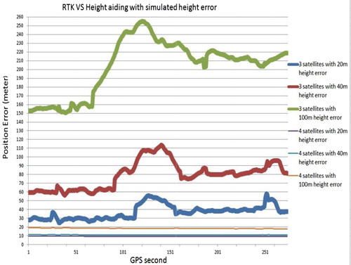
In order to further investigate the effect of large height aiding error on the position accuracy, 20 m, 40 m and 100 m errors are manually added into p4 in Equation (4) which are then used in the least squares solution for three and four satellites, respectively as shown in . Since the number of satellites visible to the receiver exerts an influence on the effect of height aiding, the more satellites visible to the receiver, the less prominent the effect of height aiding on the overall position solution. It can be seen from that 20 m, 40 m and 100 m simulated height error with three satellites produce a range of average position errors at 40 m, 80 m and 210 m (i.e. nearly doubles the height error), respectively over a period of five minutes during which the satellite elevation angle and azimuth changes constantly so as the pseduorange error. This means that the three satellite solution is more sensitive to the height error interpolated from DEMs. However, the four satellite solution is less influenced by the perturbed height aiding measurement, 20 m and 40 m simulated height error have no effect on the position accuracy of the four satellite solution (i.e. 10 m position error consistently in ). A 100 m height error in a four satellite solution caused 20 m position error which is only 10 m larger than the position error caused by 20 m and 40 m height error. So, the four satellite solution is not sensitive to the small change in height error introduced by height aiding.
6. Conclusion and future work
This paper has investigated the accuracy of the individual range measurement (i.e. the distance to the Earth centre) taken by height aiding using 1 m, 5 m and 10 m elevation data, respectively in both dynamic and static testing environments. The exact height aiding range error has been precisely quantified during the experiments under various testing conditions. Drawing on the experimental results obtained in this research which complement existing literature on this subject, it can be concluded that height aiding with high resolution 1 m LiDAR data has higher potential to enhance the accuracy, reliability and availability of personal and in-car GPS navigation especially when the number of visible satellite is low and the satellite-receiver geometry is poor. In contrast to the error budget (e.g. usually a few metres) for pseudorange measurements from the satellites, height aiding using 1 m LiDAR data can provide a more accurate and robust range measurement at one metre level or even higher if used appropriately while 5 m SAR and 10 m DEM for height aiding are less robust and accurate. However, on the one hand, the extra details captured by finer resolution LiDAR DEM may interfere the height aiding process as demonstrated in this paper. On the other hand, coarser resolution DEM data are unable to adequately represent the terrain details and thus provides a less robust range measurement, but is less likely to produce exceptional large range error and can even perform better at certain locations than 1 m LiDAR data. Moreover, height aiding contributes less to the overall position quality if there are more than three reliable satellites available to the receiver and the satellite-receiver geometry is good. Its effect is most significant when the number of satellites is down to three or the satellite-receiver geometry is poor. A solution with more than four satellites is not as sensitive to the change of range error introduced by height aiding as to the solution with three satellites. Extremely large interpolated height errors from LIDAR DSM may deteriorate the overall position quality and filtered bare-Earth LIDAR DEM is more suitable for in-car and personal navigation systems. Finally, the use of higher resolution DEM data in height aided GPS is worthy of being further investigated in various testing scenarios and applications (e.g. animal tracking). Future work may investigate the use of multi-resolution DEMs for outlier detection in weak signal environments and DEM filtering algorithms in conjunction with vehicle dynamics (e.g. speed and orientation).
Funding
This research is supported by Project 41101436 supported by National Natural Science Foundation of China.
References
- Ajmar, A., S. Balbo, P. Boccardo, T. F. Giulio, M. Piras, and J. Princic. 2013. “A Low Cost Mobile Mapping System (LCMMS) for Field Data Acquisition: A Potential Use to Validate Aerial/satellite Building Damage Assessment.” International Journal of Digital Earth 6 (2): 103–123. doi:10.1080/17538947.2011.608813.
- Ali, K., X. Chen, F. Dovis, D. D. Castro, and A. J. Fernández. 2012. “Multipath Estimation in Urban Environments from Joint GNSS Receivers and LiDAR Sensors.” Sensors 12 (11): 14592–14603. doi:10.3390/s121114592.
- Bauer, S., M. Obst, and G. Wanielik. 2012. “3D Environment Modeling for GPS Multipath Detection in Urban Areas.” Proceedings of the 2012 9th International Multi-Conference on Systems, Signals and Devices, vol. 3, 653–657. Chemnitz: IEEE Press.
- Blewitt, G. 1997. “Basics of the GPS Technique: Observation Equations.” In Geodetic Applications of GPS, edited by B Johnson, 10–54. Gävle: Nordic Geodetic Commission. ISSN 0280-5731.
- Dumble, S. J., and P. W. Gibbens. 2014. “Efficient Terrain-Aided Visual Horizon Based Attitude Estimation and Localization.” Journal of Intelligent & Robotic Systems 1– 17. doi:10.1007/s10846-014-0043-8.
- Jwo, D.-J. 2001. “Efficient DOP Calculation for GPS with and without Altimeter Aiding.” Journal of Navigation 54 (2): 269–279. doi:10.1017/S0373463301001321.
- Langley, R. B. 1991. “The Mathematics of GPS.” GPS World 2: 45–50.
- Leica, 1999. Getting Started with Static and Kinematic Surveys. Heerbrugg: Leica Geosystems.
- Li, J., and C. Jarvis. 2009. “GPS Height Aiding Computation Using Multi-resolution Digital Terrain Models.” In Proceedings of International Conference on Communications and Mobile Computing, edited by Cheng-Xiang Wang and Shan Ouyang, vol. 3, Kunming. 295–298. Los Alamitos, CA: IEEE Press.
- Li, J., C. H. Jarvis, and C. Brunsdon. 2010. “The Use of Immersive Real-time 3D Computer Graphics for Visualisation of Dilution of Precision in Virtual Environments.” International Journal of Geographical Information Science 24 (4): 591–605. doi:10.1080/13658810902989995.
- Li, J., G. Taylor, D. Kidner, and M. Ware. 2008. “Prediction and Visualization of GPS Multipath Signals in Urban Areas using LiDAR Digital Surface Models and Building Footprints.” International Journal of Geographical Information Science 22 (11–12): 1197–1218. doi:10.1080/13658810701851396.
- Li, J., G. Taylor, and D. B. Kidner. 2005. “Accuracy and Reliability of Map-matched GPS Coordinates: The Dependence on Terrain Model Resolution and Interpolation Algorithm.” Computers and Geosciences 31 (2): 241–251. doi:10.1016/j.cageo.2004.06.011.
- Mandel, C., and T. Laue. 2010. “Particle Filter-based Position Estimation in Road Network Using Digital Elevation Models.” In Proceedings of IEEE/RSJ International Conference on Intelligent Robots and Systems, edited by Ren C. Luo and Hajime Asama, 5744–5749. Taipei: IEEE.
- Ordnance Survey. 2005. A guide to Coordinate Systems in Great Britain. Southampton: Ordnance Survey Press.
- Stein, B. A. 1985. “Satellite Selection Criteria during Altimeter Aiding for GPS, Navigation.” Journal of the Institute of Navigation 32 (2): 149–157. doi:10.1002/j.2161-4296.1985.tb00898.x.
- Yildirim, O. 2013. “Results from a Comprehensive GPS Network: Natural Gas Pipeline GPS Network.” International Journal of Digital Earth 6 (2): 67–80.