Abstract
This article describes the development and validation of a novel thermoelastic stress analysis (TSA) system based on a low-cost microbolometer device. The use of a microbolometer for a highly synchronous and delicate temperature measurement breaks a longstanding and exclusive reliance on high performance, cooled photon detectors for thermoelastic applications. It is shown that despite markedly inferior noise equivalent temperature detectivity and dynamic response specifications, microbolometers are capable of achieving comparable levels of stress measurement performance. The practical implications for experimental stress analysis are significant. Microbolometers are relatively low in capital cost, small in size, have good tolerance to shock and vibration and consume less power than their photon counterparts, attributes that confer enormous practical advantages. It is argued that the emergence of TSA systems that are more affordable and better suited to in-service application could help to promote a much broader use of this powerful technique in applications across the life cycle of high value civil, maritime and aerospace assets, from the validation of finite element modelling for design to in-service structural integrity assessment. A full-scale fatigue test of a flight-critical aircraft structural component is employed as a case study to demonstrate important aspects of the capability. Future directions in the development and application of low-cost miniaturised systems are also discussed.
1. Introduction
Thermoelastic Stress Analysis (TSA) is one of the only few methods capable of furnishing a full-field measurement of mechanical stress. Yet, despite the commercial availability of TSA systems for over 30 years, and the advent of rapid staring array systems almost 20 years ago (e.g. [1,2]), the contemporary use of TSA is not as widespread as might have been reasonably anticipated by those involved in the early stages of its development. Indeed, awareness of the method within the broader engineering community seems to be low relative to optical techniques including electronic speckle pattern interferometry and in particular, digital image correlation (DIC). Admittedly, a review of such techniques would reveal a number of advantages over TSA such as a lower capital cost in relation to DIC and an ability to furnish measurements under static loading, however, TSA offers several fundamental practical advantages that will ensure that it remains an important experimental tool well into the future. The precise reasons for the modest uptake of TSA remain a matter for conjecture and debate, however, two contributing factors are reasonably clear: (1) the relatively high capital cost of commercial TSA systems, a point acknowledged by previous authors (e.g. [3,4]) and (2) a general perception outside the research community that the technique can be difficult to use.
Hardware affordability has improved significantly over the past decade (by at least a factor of two), thanks largely to a decline in the cost of staring array photon detectors. However, the improvement has occurred incrementally and to some extent has gone unnoticed within the broader engineering community. Recent advances in microbolometer technology provide an opportunity for a more radical reduction in cost as well improvements in practicality that together have the potential to transform TSA into a much more affordable mainstream technique. That objective forms the primary motivation of the present article which describes the development, validation and application of a TSA system developed using a compact low-cost microbolometer device. The system, named MiTE,Footnote1 was first reported in [5], however, that article was brief and contained few technical details. The present article provides a comprehensive account of its development, validation and application. A brief review of thermoelastic theory is followed by a description of a signal-processing methodology that eliminates the need for dedicated signal processing hardware, thereby helping to achieve a relatively low system cost, as well as a degree of portability and ruggedness that cannot be matched by systems employing cooled photon detectors.Footnote2 A validation of the system is achieved by means of a comparison between measured results and theoretical as well as numerical predictions relating to two standard mechanical test coupons. Finally, a combat aircraft full-scale fatigue test (FSFT) is used as a case study to highlight key aspects of the capability and its potential to furnish important information across the life cycle of an engineering structure, from design to through-life maintenance. The example will also be used to highlight some possible future directions for the development and application of this capability.
2 Thermoelasticity
Detailed reviews of the thermoelastic effect and TSA are available in the existing literature (e.g. [6–8]), so only a brief summary of the fundamentals is necessary here. The thermoelastic effect describes a small reversible change in the temperature of an object as it undergoes an elastic deformation. A theoretical description was reported by Lord Kelvin in 1853 [9]. The relationship is given in [6] as(1) where
is the change in temperature produced by a change in the sum of the principal stresses
,
is the absolute temperature,
is the coefficient of thermal expansion,
is the mass density and
is the specific heat at constant pressure. Equation (1) exposes a number of important properties. Firstly, as the sum of the principal stresses relate to the dilatational component of the deformation, it follows that states of pure shear produce no thermoelastic response. Secondly, a positive change in stress (increasingly tensile) produces a negative change (drop) in temperature and vice versa. Thirdly, the relation describes a reversible phenomenon meaning that a material deformed and then released recovers its initial thermal state exactly. However, for that to occur, the deformation must take place adiabatically. Since strain gradients produce temperature gradients, and loading rates are invariably finite, adiabatic conditions are never strictly attained in practice. A good working approximation can, however, be achieved in many cases by increasing the loading rate, which stems diffusion by limiting the time available for it to occur. At the other extreme, static loading represents a limiting case where the thermoelastic response is extinguished by diffusion. The reader interested in further details on any of these aspects should consult the review articles cited previously. For those that are unfamiliar with the technique, these properties could create a sense of a technique with rather restrictive limitations, however, for a great many roles, these pose little problem. Indeed, the literature is full of examples of highly successful practical applications (e.g. [10–12]).
The final remark to be made here is that the temperature variations produced by the thermoelastic effect are relatively small. For example, at the elastic limit of the Al and Ti alloys listed in Table , the variations are seen to approach . In the majority of practical cases, however, the variations are much smaller. A non-contact measurement in this context is not trivial and indeed, it was well over a century after Lord Kelvin’s mathematical description before a radiometric measurement of the effect was achieved [13]. Fifty years on that task still poses an experimental challenge, which is perhaps best appreciated by considering the sort of sensitivity that can be achieved from a raw measurement furnished by a modern high-performance cooled infrared imaging device. Take a mid-wave Indium Antimonide (InSb) array. Such a device might have a nominal sensitivity (expressed as the noise equivalent temperature detectivity (NETD)) of
or thereabouts. In a subject made of the aluminium alloy listed in Table , this would equate to a change in stress of approximately
, which is equivalent to about 70
. Anyone accustomed to using electrical resistance strain gauges is likely to find that unimpressive. Fortunately, it turns out that much better can be done with appropriate signal processing, a fact demonstrated long ago by the developers of SPATE (Stress Pattern Analysis by Thermal Emission) [14].
Table 1. Thermoelastic response of several engineering materials.
3 Microbolometer detectors
A microbolometer is a thermal detector that relies on absorption and thermal conductance for the transduction of radiant energy to an electrical signal. Compared with photodetection, thermal detection has two fundamental disadvantages in relation to the measurement of small-scale rapid temperature oscillations. The process time constant (integration time equivalent) is much longer (by about an order of magnitude) and the NETD notionally at least 3 times higher. Superficially at least, these seem like good reasons to avoid microbolometers for such a task. However, a comparison of this sort overlooks several key points. Firstly, the raw performance specifications of a detector, and particularly the rated NETD, provide an insufficient basis for a precise forecast of stress measurement performance, a point we re-examine later. Secondly, the experience of the Australian Defence Science and Technology Organisation (DSTO) suggests that the performance levels achieved by even low-grade microbolometer devices are adequate for many (and one might argue most) industrial applications. And finally, microbolometers are vastly superior to photon detectors on just about every measure of practicality. They are lower in capital cost, are more compact in size, have a better tolerance to shock and vibration and should be more reliable than cooled detectors employing closed cycle refrigerators. The authors contend that these latter factors are significant enough to outweigh minor shortfalls in performance for a great many applications. If this assertion proves correct, microbolometers could pave the way for a much broader utilisation of this powerful stress analysis technique, as remarked in the introduction.
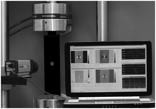
The TSA system described in the present article was developed using a FLIR A20 M (see Figure ), a low-grade commercial microbolometer camera that exemplifies the poor raw performance comparison mentioned in the previous paragraph. This device contains a 160(H) 120(V) Vanadium Oxide (VOx) array with a nominal NEDT of
, which is nearly an order of magnitude higher than that of an InSb array, and over twice that of newer microbolometer devices. Output is in 16-bit digital form and is supplied at a fixed frame rate of
.
4 Sensitivity enhancement
An NETD of equates to a stress measurement noise floor of approximately
, a value that suggests a poor basis for a precise stress measurement capability. It is not the case. As the developers of SPATE showed, providing the load signal is known and the noise in the radiometric signal is chiefly temporal and random, the threshold stress measurement sensitivity of the detector can be improved significantly with signal processing. Consider an applied load that varies harmonically in time, viz.
(2) where
is the load amplitude and
is the circular frequency. Equation (1) is linear, so the thermoelastic response should occur at the same frequency.Footnote3 It follows that if the loading is sufficiently rapid to negate the effects of diffusion, the thermoelastic response can be written as [16]
(3) Where
is the temporal average of the load,
accounts for any background infrared emission uncorrelated with the load, and the constant of proportionality
is a function of the material properties, which are normally known and the stress amplitude which is sought. A least squares estimate for the constant
is obtained by minimising the function,
(4) where the subscript
is an index to time, the superscripts
identify the detector cell,
is the number of temporal samples and
is the oscillatory component of the load (i.e. stripped of its offset). This produces the set of equations
(5)
Since varies about a zero mean, it follows that,
(6)
represents the linear correlation between the radiometric and load signals, and for convenience is referred to as the correlation signal hereon. A cross-correlation of this type works well in removing noise. Indeed, where the noise in the measurement
is random Gaussian, the process leads to a
decline in the standard deviation of
. The implication is that cross-correlation can achieve a sensitivity that has no limit, which seems unrealistic and it is. The central reason is that measurement noise is not always uncorrelated. A variety of causes exist, however, an important source in the context of staring arrays is fixed pattern noise (FPN) relating to variations in the offset and gain characteristics of detector elements across the array [17]. Variations in the latter are the most relevant since these are indistinguishable from variations in the thermoelastic response in the scene (i.e. are correlated with the load signal), and appear as a bias in the estimate
. Modern photon cameras are susceptible and typically include a ‘non-uniformity correction’ facility in the system firmware to deal with it [18]. Although effective, some degree of non-uniformity always remains. This discussion raises an important cautionary point about the NETD, the chief figure of merit for detector performance and a value that makes no distinction between the two types of noise. The upshot is that based on NETD alone, a photon detector should always outperform a microbolometer in terms of stress sensitivity, however, the latter point suggests that this need not necessarily be the case, or at the very least, the margin in performance might not be as great as the difference in NETD would suggest.
5 System implementation
Equation (6) assumes a synchronous acquisition of the infra-red data stream and the load reference signal. This is easily achieved in practice with a frame-grabber. However, the use of dedicated hardware was ruled out for the present implementation because of the adverse impact on the affordability, size and ruggedness of the system, as well as the added future risk of obsolescence. Those considerations led to a decision to base development on an off-the-shelf notebook computer. Only two specific requirements were imposed: the availability of an IEEE1394 interface to allow for a direct acquisition of the digital infrared signal from the A20 M and a PCMCIA slot to accommodate an analogue to digital converter (ADC) for the acquisition of the load reference. Incidentally, this ADC is the only peripheral device in the system dedicated to the TSA process.
The pursuit of a low-cost and compact hardware configuration raises some technical challenges. As anticipated, an analysis of the load and infrared signals acquired using this arrangement revealed the presence of significant time delays. This finding, along with other considerations, meant that a real-time computation of the correlation sums was impractical. A pseudo-real-time approach was used instead. The sums were calculated off-line in a piecewise continuous sense using stored blocks of data and then recursively averaged as a final step. The approach takes marginally longer than a real-time computation, but the difference is largely negligible, since at the loading frequencies typically employed in TSA () data acquisition accounts for the bulk of the total analysis time.
The process was tested using an experimental apparatus comprising a small Peltier cell driven sinusoidally by a function generator. A relatively low drive frequency of was required to accommodate the slow thermal response time of the Peltier cell. The value
was computed for an arbitrary detector cell
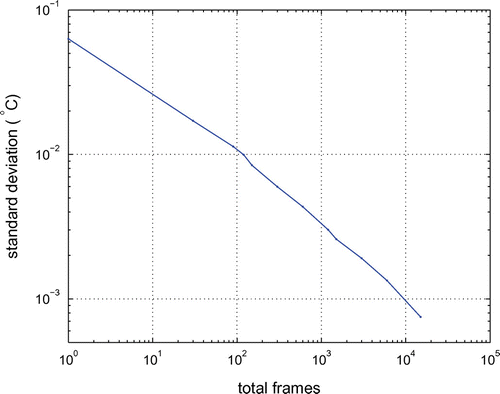
as a function of the number of temporal samples or image frames. Figure plots the decline in signal noise. The trend is approximately log-linear and the improvement in sensitivity after 10,000 samples is nearly two orders of magnitude which is roughly consistent with theory. This improvement in the noise floor obviously translates to a significant difference in the apparent stress measurement sensitivity. For the hypothetical aluminium structure considered earlier, this value improves to less than
One should recall that this relates to a single pixel and so excludes the influence of FPN.
Recall from Equation (1) that an adiabatic thermoelastic response is precisely anti-phase relative to the load signal. In practice, some deviation in that phase relationship will invariably occur due to the effects of heat transfer, mainly conduction within the sample. However, in the present system, the load and infrared signals are skewed by an unknown system delay, which adds an extraneous phase variation. In fact, three delays are present. These can be conveniently expressed in terms of an adjustment to the phase of the load signal, viz.(7) where
denotes a phase delay due to the detector integration process,
refers to a transport delay between sampling of the load and infrared signals, and
describes a scan delay between detector cells in the array. Each delay has a significant influence on the correlation process as explained in the following.
5.1 Scan delay
The integration and readout of the detector array occurs sequentially such that each detector observes the scene at a slightly different time in the loading sequence. The effect is shown in Figure which maps the argument of the correlation signal (Equation (6)) from a nominally uniform scene where the infrared emittance was varied harmonically at . The experimental apparatus used to produce this result is described later.
Figure 3 Linear greyscale image of the phase distribution measured across a notionally uniform scene. The spiral-shaped object is an artefact unrelated to the scan delay and can be ignored.
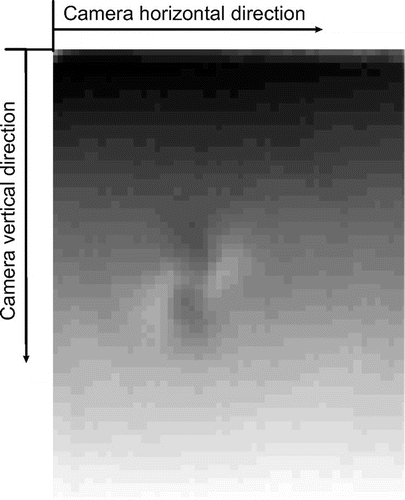
In the absence of a scan delay, the argument should be uniform, so the result in Figure confirms a significant delay and implicates the vertical scan as the main cause. The delay associated with the horizontal scan rate is negligibly small in comparison. The vertical scan rate is readily deduced from the variation in argument in Figure and was found to be approximately per vertical line. This corresponds to a delay between the integration of the first and last pixels in an image of
, or marginally below the reciprocal of the frame rate. Interestingly, the analysis revealed a bottom-up integration for the present detector – i.e. the scan commences at the bottom of the array. A second A20 M was found to have a top-down integration suggesting that at least two different imaging cores were used in the A20 product line.
5.2 Detector dynamics
A photon detector accumulates photons over a prescribed interval of time, so its dynamics are consistent with that of an ideal integrator. A bolometer behaves differently. It relies on infra-red absorption and thermal conduction, so its dynamics are fixed by a time constant that depends on the thermal properties and physical dimensions of the detector element. The dynamic response can be described approximately by the first-order differential equation(8) where
is the time constant,
is the detector temperature and
is a forcing term that relates to the incoming photon flux. The impulse response follows by setting
, viz.,
(9)
This leads to the following frequency response function:(10)
(11)
(12)
(13)
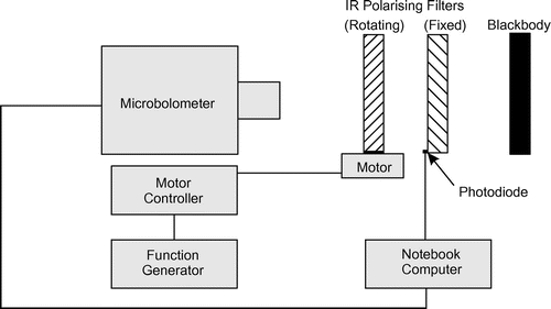
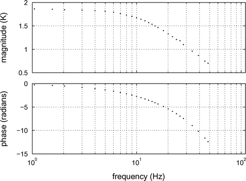
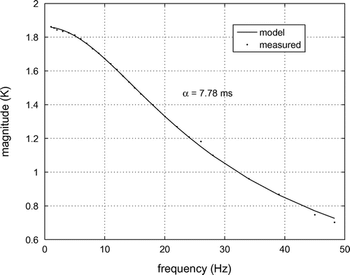
The time constant of the A20 M detector was unknown and had to be determined by means of an experiment. The apparatus constructed for that purpose is shown in Figure . It comprises of a rotating infrared polarising filter in front of a blackbody area source held at constant temperature. Viewed through the filter, the scene has a uniform intensity that modulates as the filter rotates. Figure plots the response spectrum of the detector measured for modulation frequencies in the range .
The time constant can be deduced from either the phase or magnitude spectrum. The latter was preferred here since the measured phase includes the effect of the transport delay mentioned previously, which is yet to be determined. The time constant was found by minimising the following objective function:(14) where
is the measured frequency response magnitude, and
is an unknown constant. The summation was taken over the frequency range
. Choosing an arbitrary detector element in the array, a Nelder–Mead Simplex algorithm was applied to solve for the unknowns, yielding a time constant of 7.78 ms. Figure confirms an excellent model fit.
5.3 Transport delay
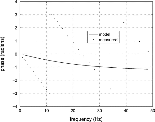
The transport delay stems from the skewed acquisition of the radiometric and load reference signals. The effect of the delay is significant, as illustrated in Figure , which compares the measured phase spectrum with a prediction based on the first-order model previously validated by the result in Figure . Assuming the scan delay has been accounted for, the phase variation in the detector signal can be expressed by the model,(15) which consists of the delay due to the detector dynamics, the unknown transport delay
, and some phase offset
. Again, least squares is used to solve for the unknowns, viz.
(16) ,which results in the following pair of linear equations:
(17)
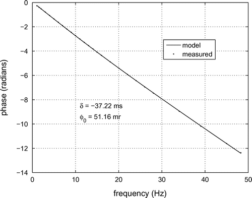
Solving these over the frequency range , yields values of
and
. Figure compares the measured spectrum to the phase model using these values. The agreement is excellent which confirms the accuracy of both the proposed phase model and the estimates themselves.
In summary, four corrections need to be implemented in the present system to produce an accurate thermoelastic response measurement. These comprise three phase corrections; for the scan delay, detector time constant and system transport delay, and an amplitude correction for the time constant. The computational expense involved in implementing these is negligible and the process is opaque to the user. The parameters need to be only determined once for a given camera and can be included as part of the system firmware.
The gain and offset spatial uniformity and stability of an array were previously described as factors essential to the achievement of a low noise-floor. For the A20 M, this is accomplished by means of an internal calibration applied automatically through the camera firmware. In the present implementation of MiTE, a calibration is forced prior to the capture of each data block. The duration of these blocks is also kept relatively short to minimise the effect of any drift in the detector characteristics.
6 Experimental validation
In the absence of any prior experience in the use of a microbolometer for stress analysis, validation of the new facility was an important step and therefore given close attention. Two separate test cases were considered in the evaluation. Both involved relatively straightforward coupon geometries; a uniaxially-loaded plate containing a circular hole and a beam exposed to four-point bending. These were selected chiefly on the grounds that the stress distributions are relatively simple and readily deduced by either analytical or numerical means.
6.1 Plate with a hole – validation against finite element analysis
The specimen was a rectangular plate of aluminium alloy approximately 2 mm thick, 100 mm wide and 400 mm long with a circular hole 12.35 mm in diameter at its centre. A thin coating of matt-black paint was applied to the specimen to ensure a high and uniform emissivity. Testing was done under uniaxial sinusoidal loading at constant amplitude.
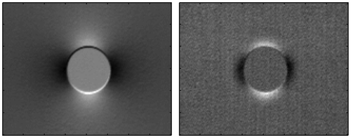
Figure shows the in-phase and quadrature components of the measured signal after one minute of processing at a frequency of 10 Hz. Dark shades in the left image correspond to a negative correlation or a tensile bulk stress, and light shades to a positive correlation or a compressive bulk stress. A non-zero quadrature component confirms the presence of heat diffusion, which, as expected, is strongest near the edge of the hole where the stress gradients are the largest. The inferred stresses in these regions are consequently biased. This is best appreciated by comparing the measured in-phase component to the actual stress distribution as deduced by finite element analysis (FEA), which for the simple geometry at hand, can be expected to furnish reasonable accuracy.
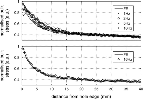
Figure provides a comparison between the measured in-phase signal and the corresponding bulk-stress predictions along the horizontal line of symmetry, where the origin is at the hole edge. Thermoelastic response measurements are shown for loading frequencies in the range 1–16 Hz. As expected, an increase in frequency leads to improved agreement with the model prediction. The measurement at 16 Hz is largely coincident with the prediction suggesting firstly that pseudo-adiabatic conditions have been attained and secondly that the system is behaving as it should in this circumstance.
6.2 A beam in four-point bending – analytical solution
Despite the convincing nature of the comparison shown in Figure , the result provides only a qualified basis for validation since the solution furnished by FEA is not exact. A second test case was developed to provide an independent and arguably more rigorous basis for comparison. The case chosen is a beam in pure bending which is an attractive problem for two reasons. The depthwise strain profile is linear and with an appropriate loading configuration, the heat diffusion is confined to one spatial dimension. This allows the thermoelastic response of the beam to be derived analytically, which confers another advantage. The availability of an analytical solution helps to clarify an important practical point regarding heat conduction that we explore a little further on.
6.2.1 Theory
The general non-adiabatic thermoelastic response of a body is described by the heat-diffusion equation with an appropriate source term, viz.(18) where
(19)
is the thermal conductivity and
is the change in temperature relative to an initial temperature
. Pure bending results in a linear strain distribution, and if the load oscillates harmonically, the strain across a beam of depth
can be written as:
(20) where
, with the origin taken at the compressive surface of the beam,
is the strain magnitude at that point, and
is an arbitrary phase offset. By condensing some of the terms associated with the thermoelastic source strength in a constant
, and observing that for a four-point bend configuration, the source only varies as a function of
, then the governing equation becomes,
(21) ,Where,
is the thermal diffusivity. In practice, heat transfer to the environment is normally negligibly small (see [6]). Consequently, adiabatic conditions are a reasonable assumption for the boundaries
. Under these conditions, Equation (21) has the following solution
(22)
(23)
In the absence of heat conduction, the solution simplifies to(24)
6.2.2 Experiment
The specimen was machined from thick
plate stock to side dimensions of
. Figure illustrates the loading arrangement. As in the previous case, matt-black paint was applied to the surface of interest.
Figure 11 Schematic illustration of a simply supported beam loaded in four-point bending. Measurements were taken along the line AA′.

The thermoelastic response of the beam was measured under a sinusoidal load applied at frequencies in the range 0.5–5 Hz. Values along the vertical line of symmetry AA′ (see Figure ) were compared with theoretical predictions furnished by Equation (22) using the following material properties [19]: ,
and
. Figure shows the comparison for the 0.5 and 5 Hz cases.
Figure 12 In-phase (solid line) and quadrature (dashed line) profiles at 0.5 Hz (top) and 5 Hz (bottom). Lines correspond to theory and markers to measurements from the MiTE system.
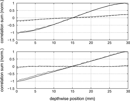
The agreement at both frequencies is seen to be excellent. A slight discrepancy occurs in the in-phase component on the compressive side of the neutral axis (), however, this can be explained in part by the effects of friction and localised plastic deformation at the loading points.
6.3 Remarks on the effects of heat conduction
The 0.5 Hz result underscores the need for caution in applying the adiabatic expression for the thermoelastic effect to experimental data. The strain profile derived from the measured response would in this case contain a significant bias resulting in a conservative estimate of the strains at the extreme surfaces of the beam. One should note a similar effect in the results shown in Figure . The pattern is no coincidence. This conservative tendency is a feature of heat conduction that needs to be kept in mind, especially in applications such as airframe structural lifing where a small conservative bias in a peak stress estimate has the potential to erode the conservatism factored into a fatigue life prediction.
This problem can be dealt with in two main ways. The first and preferred option is to ensure that the loading rates are high enough to render diffusion effects negligible. Where that is not possible, modelling may provide a solution. In fact, Equation (18) creates the impression of a straightforward inverse problem. This could not be further from the truth as even small amounts of experimental noise render an inverse solution intractable. A known functional form for the strain distribution is an enormous advantage [20], as in the present example, but this sort of knowledge is seldom available in practice.
Heat conduction can, in theory, be dealt with in a more generalised sense using a hybrid analytical/experimental approach. Measurements of the thermoelastic response of a structure across a range of frequencies, whether obtained by means of a frequency sweep or a sufficiently rich loading spectrum, should, with an appropriate model for heat conduction, allow for the determination of an adiabatic response. Work along these lines has appeared in the literature. For example, in [21], an approach is described where the bulk stress distribution is locally approximated by a power law which is used in the heat diffusion equation to relate the attenuation caused by conduction to a corresponding phase shift. The method was shown to perform quite well under relatively complex test conditions.
FEA offers another avenue for tackling complex conduction problems, and provides, arguably, the most general and powerful approach to the issue. Use of FEA in this context might appear cumbersome, but one should note that for many high value engineering structures, finite element (FE) models will already be available, if not for the entire structure, then certainly for known critical areas. Where the model is structural, an adaptation to a thermal model should not be difficult. At the modulation frequencies employed in TSA (generally < 20 Hz), a harmonic heat diffusion problem would require only a relatively coarse mesh, and since thermal transients are irrelevant, the analysis itself is quasi-static. In cases where TSA is applied to validate or refine FE models, the approach is intuitive and might proceed as follows: a prediction of the stress distribution furnished by a structural FE model serves as the heat source for a corresponding thermal analysis yielding a non-adiabatic thermoelastic response prediction that can be compared directly with the TSA result. Iterative refinement of the model continues until the predicted response matchesFootnote4 the TSA measurement. Generally, a broad-band thermoelastic response measurement (i.e. a measurement taken at multiple frequencies) would help the process resolve the effects of conduction from spatial variations in the source (or bulk stress) and thereby help with rates of convergence. An approach of this type has other advantages which will be discussed shortly.
7 Application to aircraft component lifing – a case study
As part of a mid-life structural upgrade [22] for the RAAF F/A-18 fleet, an extensive FSFT programme was carried out on the critical centre-barrel structure of the airframe. The centre-barrel consists of three main bulkheads which connect to the wings and landing gear and react the primary flight and landing loads into the fuselage of the aircraft. It is a highly stressed structure and is prone to fatigue. The main idea of the FSFT is to understand well ahead of time, where and when fatigue failure is likely to occur in service. Failures in test articles are extensively studied using a combination of experimental (strain gauges), predictive (FE modelling) and analytical (fractography) tools but TSA has also had an important role in a number of facets of these tests. One of the first was in validating FE predictions of the stresses in a critical region in the lower part of the aft bulkhead, close to where failure of the centre-barrel normally first occurs. The area of broad interest has been painted black in the test article shown in Figure , however, the examination in this case focused on a smaller area in the vicinity of the hole arrowed in the close-up.
Figure 13 TSA of the aft bulkhead in an F/A-18 centre-barrel. Top-right photograph shows a close-up of the hydraulic hole under inspection (arrowed). Bottom-right photograph shows a close-up of the A20 M fixed to the bulkhead by means of a small articulated arm.
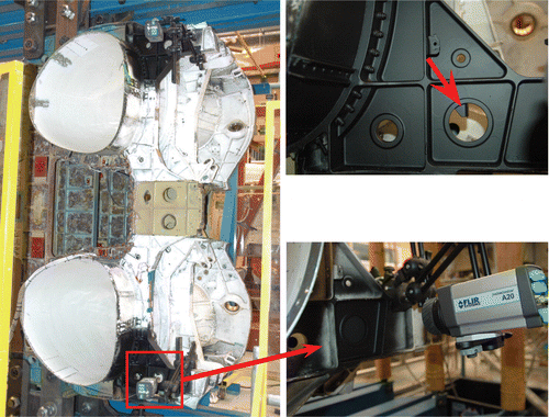
In initial deliberations on the problem, the authors were concerned by two aspects in particular. The first was that the loading rates were low by TSA standards, about 100 mHz in the course of full flight-spectrum loading and no more than 1.0 Hz under a constant amplitude loading at 8% of the peak spectrum load which was the condition under which the test was eventually done. The second concern related to the displacement of the structure under load which was large enough (many mm’s) to rule out a fixed observation, at least without some form of motion compensation. It was in dealing with this particular issue that the notional practical superiority of a microbolometer was demonstrated in a most emphatic way. The the simplest and most effective remedy for the motion was to attach the detector to the loaded structure. The approach was highly unconventional and there was no precedent for it at DSTO, where photon-based TSA systems of various persuasions have been applied to aerospace problems for over two decades. However, the solution seemed obvious and a compact low-cost device made it straightforward, both from the viewpoint of the engineering required to fix the device to the bulkhead, and from a risk perspective in that in the eventuality of a major structural failure, the financial loss incurred would be low.
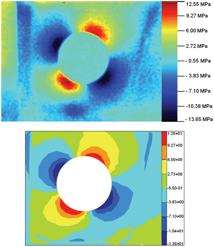
Figure compares the stress distribution furnished by MiTE with the corresponding FEA prediction for the region surrounding the hydraulic hole. The agreement is excellent, with peak tensile and compressive stress values matching remarkably well. A noticeable quadrature signal confirmed the presence of heat conduction which was entirely anticipated given the low loading rate, however, the effect was evidently slight, helped no doubt by the scaling effect of the large hole (). No analysis was done of the errors caused by heat conduction in this case, in part because of the excellent agreement but mainly because of lack of time. The omission is regrettable as a confidence interval on the measurement would have furnished a more rigorous basis for assessing the FE result. It is speculation now but the FE model available for this structure could possibly have been applied for this purpose, broadly in line with the strategy outlined previously.
8 Variable amplitude loading
A constant amplitude sinusoidal loading offers an experimentally convenient basis for TSA, and is preferred for most laboratory investigations, but it is not a necessity. Indeed, the cross-correlation process at the core of the MiTE system can be applied in general to any load sequence that can be expressed as a sum of harmonic terms of the type in Equation (2). In this sense, MiTE is no different to commercial systems and copes easily with a variable-amplitude load sequence. We illustrate with an example.
Consider the coupon shown in Figure , which replicates the main details of structural significance in a small fatigue-critical section of the lower wing-skin of the F-111C aircraft, in a location referred to as FASS 281.28.Footnote5 The coupon was manufactured from alloy to match the actual wing-skin construction material. The feature of chief interest here is a depression in the main integral stiffener, the purpose of which is to facilitate fuel-flow between adjacent bays of the wing-box fuel tank. In meeting its primary function however, the design introduces a stress concentration that leads ultimately to premature fatigue cracking [23].
Figure 15 Close-up of an F-111 lower wing-skin coupon (left) with an arrow highlighting a fatigue-critical feature under examination by MiTE (right).
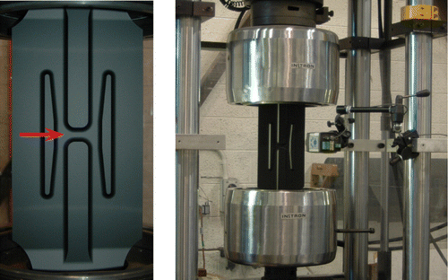
The variable amplitude loading applied to the coupon was derived from an F-111C flight-load sequence. This sequence contains relatively large compressive load excursions which pose a buckling risk for the coupon, which in flexure is far less rigid than the actual wing skin because of the absence of spars and other supporting members. The requisite flexural stiffness can be achieved by fitting anti-buckling restraints to the coupon. However, it proved far more convenient to simply strip compressive loads from the sequence. Figure shows part of the modified sequence measured at the load-cell during an actual test, along with the corresponding amplitude spectrum. The load-points in the sequence were applied to the coupon at a rate of two per second. As a benchmark for comparison, a thermoelastic scan was also done under pure sinusoidal loading at an equivalent frequency (1 Hz) and rms equivalent amplitude. Figure shows the measured stress distributions. The results are virtually identical. The test duration was approximately 6 min in both cases.
Figure 16 Representative sample of the modified flight-load sequence (top) applied to the F-111C coupon, along with the corresponding magnitude spectrum (bottom).
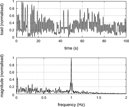
Figure 17 Comparison of TSA results obtained under a variable amplitude flight-load spectrum (left) and pure sinusoidal loading (middle). Also shown is the quadrature component from a rear-side (external wing-surface) inspection (right).
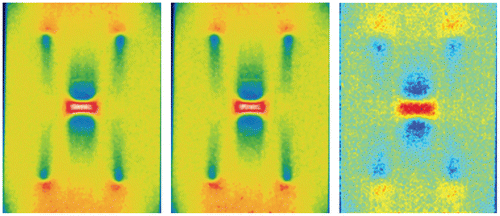
It is worth noting that an analysis confined to the primary frequency in a variable amplitude load sequence ignores potentially valuable information contained elsewhere in the spectrum. At the most basic level, the inclusion of response components close to the primary frequency should foster some improvement in the signal-to-noise ratio of a stress measurement. There are, however, potentially more significant opportunities. A broad-band measurement of the thermoelastic response offers information that might help to retrieve an adiabatic response – a possibility noted previously in this article. Conceivably, the process used to achieve that could also furnish information about stresses beneath the near-surface layer providing a virtual through-thickness probing capability.
Exploiting heat conduction as a means of measuring internal stresses is not a new idea and was first raised in [24]. Its major appeal is that it might provide a way of addressing problems where access for a customary line-of-sight inspection is not available. The present example serves as an excellent case in point and is worth discussing a little further. The inside surface of the wing skin is inaccessible to inspection, other than perhaps visibly with a borescope, which means the results presented in Figure could not have been achieved in an in-service scenario, nor for that matter, in an FSFT of a wing. The external wing surface is of course accessible, but an adiabatic inspection from that side would, by definition, yield no information about the stress state at the inside surface of the stiffener depression. In this context, heat diffusion can play a constructive role. If the loading rate is appropriately low, the thermal response measured at the external surface will include contributions from stresses beneath the surface. A rough estimate of the frequency required to permit diffusion through the wing-skin is obtained by setting the diffusion length () equal to the skin thickness, which is approximately 4 mm, i.e.
(25) where the thermal diffusivity
has been assigned a value of
. This frequency happens to coincide with the primary component of the load sequence, which suggests that evidence of the stress state at the depression should be apparent in an inspection of the rear side of the coupon. Figure provides confirmation of that, noting that the quadrature component is shown instead of the in-phase component to emphasise the importance of conduction to this type of probing inspection. It is surmised that such experimental information, augmented with similar information derived from other frequencies contained in the load spectrum (Figure ), should permit an estimate of the far-side stress distribution. A study exploring this possibility is currently underway.
It is to be noted that constructive uses of heat diffusion in TSA have been demonstrated before. As well as the example in [24], the principle was used in [25] to develop a way of decomposing individual strain components in polymer composite laminates, and in [26] to investigate internal surface flaws.
9 Future directions
The overarching objective in developing the MiTE system was to create a facility that would enable a broader utilisation of TSA. The present article has addressed the central part of that objective which is the development and validation of the capability itself. In providing adequate coverage of that aspect however, little space has been left to canvass the practical implications of the capability, which are thought to be significant. Such a discussion is planned for a sequel to the present article however, it would be remiss here not to at least briefly outline one of the more ambitious possibilities, which involves structural health monitoring (SHM).
Interest in SHM has steadily grown over the years in response to an increasing awareness of the infrastructure sustainment challenges emerging across the aerospace, maritime and civil sectors. The central idea in SHM is integrated sensing and for the most part, the types of sensor technologies that have attracted the greatest interest have been those that are most amenable to structural integration, i.e. contact sensors such as optical fibres, electrical resistance strain gauges and solid state piezoelectric devices. Each has its virtues, but notably none has the capacity to furnish a full-field measurement of stress which provides in principle an unrivalled basis for the diagnostic and/or prognostic assessment of structures susceptible to load-induced failure [27]. The connection with the capability described in the present article should be clear. If one examines the centre-barrel application described previously, it will be noticed that all but one of the key elements of structural health monitoring were there. What was missing was persistent or periodic observation, however adding that it involves nothing more than leaving the systems in place.
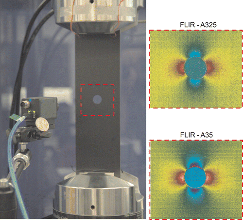
The idea of a nexus between TSA and SHM is an attractive prospect which could have significant implications for high-value structural asset management. Indeed, current efforts at DSTO in developing the next generation of the MiTE system have been shaped with this in mind. Initial work along these lines has focused on the integration of the most recent crop of microbolometer devices which are considerably more advanced than the A20 M. Figure illustrates some preliminary results from recent testing of two such devices; the FLIR-A325 and the FLIR-A35. Both are based on VOx detector technology and have almost identical performance specifications; an NETD of approximately , arrays of
and
respectively, and a frame rate of 60 Hz. All else being equal these improved specifications should translate to better stress measurement performance. Whether this has been achieved will be known shortly once the relevant evaluations are completed, however regardless of the outcome, the results in Figure are significant in verifying that these newer devices are capable of rendering a useful stress measurement. The result for the A35 is especially encouraging as this device is considerably smallerFootnote6 than the A20 M and is one of a growing class of miniature microbolometer devices that create a positive outlook for the development of an in situ structural monitoring capability based on TSA.
10 Conclusion
This article has given a detailed account of the development, validation and application of a novel TSA system based on a compact low-cost microbolometer device. Validation of the system was approached by comparing measurements with predictions furnished by FEA and analytical modelling for two standard coupon geometries. An experimental case study was then employed to underscore the key points of practical difference between this new capability and existing photon-detector-based commercial tools. It is hoped that the emergence of TSA systems that are more affordable and better suited to in-service application will foster a much broader use of this powerful technique in applications across the civil, maritime and aerospace sectors.
Acknowledgements
The authors dedicate the article to Dr Sami Weinberg, who turned some roughly written notes into the elegant and robust computer code, underpinning the capability described in this article. The contribution of Mr Matt Pelosi to the mechanical testing of the F-111 coupon is also gratefully acknowledged as is the effort of Mr Chris Brooks in achieving the results in Figure .
Notes
1. Microbolometer ThermoElasticity.
2. This includes all previous and present commercial TSA systems.
3. A response also occurs at the second harmonic [15], but is much weaker and can be ignored for most cases.
4. In a least-squares error sense.
5. Forward Auxillary Spar Station.
6. By a factor of five in volume and three in mass.
References
- Ryall TG, Wong AK. Infrared staring arrays and digital signal processing. In: Proc. sem 50th annual spring conference on experimental mechanics, Michigan, USA; 1993 June. p. 730–739.
- Lesniak JR, Boyce BR. A high-speed differential thermographic camera. In: Proceedings of sem Spring Conference on Experimental Mechanics, Baltimore, Maryland; 1994. p. 491–497.
- Dulieu-Barton J. Guest editorial. The Journal of Strain Analysis for Engineering Design. 2008;43:i–iii.
- Pitarresi G, D’Acquisto L, Siddiolo AM. Thermoelastic stress analysis by means of an infrared scanner and a two-dimensional fast fourier transform based lock-in technique. The Journal of Strain Analysis. 2008;43:493–506.
- Rajic N, Weinberg S, Rowlands D. Low-cost Thermoelastic Stress Analysis. Materials Australia. 2007;40.
- Harwood N, Cummings WM. Thermoelastic stress analysis. Bristol: Adam Hilger; 1991.
- Dulieu-Barton JM, Stanley P. Development and applications of thermoelastic stress analysis. The Journal of Strain Analysis for Engineering Design. 1998;33(2):93–104.
- Pitarresi G, Patterson EA. A review of the general theory of thermoelastic stress analysis. The Journal of Strain Analysis for Engineering Design. 2003;38:405–417.
- Thomson W. On the dynamical theory of heat. Transactions of the Royal Society of Edinburgh. 1853;20:261–283.
- Wong AK, Richmond M, Ryall TG. structural assessment of the orion P3 wing leading edge by a state-of-the-art thermal imaging system. In: Proc. 6th August Aero. conf.; Barton (Australia); 1995. p. 795–800.
- Tomlinson RA, Patterson EA. Examination of crack tip plasticity using thermoelastic stress analysis. In: Thermomechanics and infra-red imaging, volume 7. Conference Proceedings of the Society for Experimental Mechanics Series; Springer: New York; 2011. p. 123–9.
- Diaz FA, Patterson EA, Yates JR. Assessment of effective stress intensity factors using thermoelastic stress analysis. Journal of Strain Analysis. 2009;44:621–631.
- Belgen MH. Structural stress measurements with an infrared radiometer. ISA Transactions. 1967;6:49–53.
- Mountain DS, Webber JMB. Stress pattern analysis by thermal emission (SPATE). Proceedings of the Society of Photo-optical Instrumentation Engineers. 1978;164(3):189–196.
- Wong AK, Sparrow JG, Dunn SA. On the revised theory of the thermoelastic effect. Journal of Physics and Chemistry of Solids. 1988;49:395–400.
- Ryall TG, Wong AK. Design of a focal-plane array thermographic system for stress analysis. Experimental Mechanics. 1995;35:144–147.
- Shkedy L, Amir O, Calahorra Z, Oiknine-Schlesinger J, Szafranek I. Temperature dependence of spatial noise in InSb focal plane arrays. Proceedings of the SPIE. 2000;4028:481–488.
- Perry DL, Dereniak EL. Linear theory of nonuniformity correction in infrared staring sensors. Optical Engineering. 1993;32(8):1854–1859.
- Davis Joseph R, editor. Properties and selection: nonferrous alloys and special-purpose materials. Vol. 2. Novelty (OH): ASM Intl; 1990.
- McKelvie J. Temperature dependence of spatial noise in InSb focal plane arrays. In: Gasper B, editor. SPIE proc. 2nd int. conf. on stress analysis by thermoelastic techniques; London. Vol. 731; 1987. p. 44–53.
- Gallotti A, Salerno A. Gallotti A, Salerno A. Automatic procedure for the correction of thermoelastic stress analysis data acquired in nonadiabatic conditions. Review of scientific instruments. 2005;76(12):124903-1–7.
- Swanton G, Robertson L. Developments with the F/A-18 FINAL centre barrel test program. In: Proceedings of aiac14 – the fourteenth Australian international aerospace congress; Melbourne, Australia; 2011.
- Boykett R, Walker KF. F-111C lower wing skin bonded composite repair substantiation testing. Melbourne: Defence Science and Technology Organisation; 1996 . DSTO-TR-0480.
- Lesniak J. Internal stress measurements. In: Proc. 6th congress on experimental mechanics, SEM; Bethel, CT; 1988 June. p. 825–9.
- Wong A. A non-adiabatic thermoelastic theory for composite laminates. Journal of Physics and Chemistry of Solids. 1991;52(3):483–494.
- Sathon N, Dulieu-Barton JM. Damage analysis of internal surface flaws using thermoelastic stress analysis. Key Engineering Materials. 2005;293–294:279–286.
- Rajic N. Thermoelastic stress analysis – emerging opportunities in structural health monitoring. In: Proceedings of the 4th Asia-pacific workshop on structural health monitoring; 2012 december 5th–7th; Melbourne, Australia: Key engineering materials, special edition ‘structural health monitoring: Research and applications’; 2013.
