Abstract
A part of the experimental program FUBILA was dedicated to the study of core physics characteristics of full MOX BWR cores by testing five experimental cores: a core inserted with a B4C control blade, a core loaded with UO2 fuel rods, the core loaded with Gd2O3-UO2 fuel rods, a core loaded with 10 × 10 MOX assemblies and a core loaded with time-elapsed MOX fuel. The present article describes analysis results of the experimental data with deterministic analysis codes and a continuous energy Monte Carlo code coupled with major nuclear data libraries. The calculated critical k eff's with the Monte Carlo calculations range from 0.999 to 1.007. Those of the transport calculations with sixteen energy groups are close to those of the Monte Carlo calculations while those of diffusion calculations with the same sixteen energy groups are systematically smaller by −0.3 to −0.5% Δk than those of the Monte Carlo calculations. The RMSs of differences between the calculated and measured core radial fission rates are 2 to 3%, 1 to 2%, and 1 to 2% for the diffusion, transport and Monte Carlo calculations, respectively. For the analysis of the Gd2O3-UO2 fuel rod loaded core, the C/Es of the radial fission rates were improved by adopting a detailed lattice calculation model and a newly measured thermal and resonance cross-sections of Gadolinium.
1. Introduction
The Nuclear Safety Commission of Japan (NSC) suggested in the report, “Full core loading of mixed oxide fuels in advanced boiling water reactors,” [1] that the current analysis methods for safety design and evaluation of light water reactors should be advanced based on the systematic studies: (i) validation of burnup calculations by using fuel postirradiation examination data, (ii) that of nuclear design calculations by using critical experiments, and (iii) that of nuclear design calculations of irradiated fuel. In order to extend database for the above validation study (ii), the Japan Nuclear Energy Safety Organization (JNES) has implemented a core physics experimental program FUBILA [Citation2–Citation12]. Footnote1 It aimed at obtaining the core physics characteristics of full MOX BWR cores, which consisted of high Pu-content BWR MOX assemblies for achieving high burnup of fuel. Part of the program was the measurements of various types of reactivity effects, which were performed using a neutron source multiplication method in sub-critical experimental cores. Yamamoto et al. [Citation11] have reported the experimental method and results, and the neutronics analysis results. The other part of the experiments was conducted at the critical state of the experimental cores, where critical masses, core fission rate distributions and other core characteristics were obtained. The first series of the critical experiments was on in-channel void fractions in MOX assemblies at power operating conditions, and the neutronics analysis of the experimental data was reported in Yamamoto et al. [Citation9]. The second series of the experiments was on a core inserted with a B4C control blade, a core loaded with UO2 fuel rods, a core loaded with Gd2O3-UO2 fuel rods, a core loaded with 10 × 10 MOX assemblies and a core loaded with time-elapsed MOX fuel, which are hereafter referred to as “control blade core,” “UO2 rod core,” “Gd2O3-UO2 rod core,” “10 × 10 MOX assembly core” and “time-elapsed reference core,” respectively. The neutronics analysis of the second series of the experimental cores was performed using typical diffusion and transport calculation codes in order to evaluate the calculation accuracies. The analysis was also conducted using a continuous energy Monte Carlo calculation code with major nuclear data libraries to obtain the reference calculation results to be compared with those of the deterministic calculation codes and also evaluate accuracies of the nuclear data libraries.
The first part of the present article describes the core configurations and measurements, and the second part the neutronics analysis methods and results. The third part shows the conclusions.
2. Core configurations and measurements
2.1. Core configurations
The experimental core was contained in a double-wall cylindrical tank made of AG5 (Aluminum alloy) with 1.15 m inner diameter and 1.08 m height, which was filled with light water, as shown in . The inner tank was held in an outer cylindrical tank, and water always overflowed out from the top of the inner tank through the gap between the two tanks and was led to a temperature-regulation system during the experiments. The test fuel rods were supported by four grids, two of which were set at the level higher than the top of the effective part (80 cm) of the fuel rods, and two of which at the level lower than the bottom of the effective part. Four safety clusters, which were each inside of the four cylindrical tubes on the top grid in , were arranged to be inserted into the driver region. They were completely withdrawn from the core during the experiments. The number of the MOX rods was adjusted so that the core reached an almost critical condition. A pilot rod, which was installed in the driver region (not seen in ) and had reactivity worth less than a half dollar, was used for finally approaching criticality by adjusting the inserted length. The axial configuration of the core structures and the fuel rods are shown in Refs. [Citation4] and [Citation10].
Figure 1. Picture of a core tank loaded with MOX rods and structures for the control blade core [Citation4]. Note: the number of MOX rods in the driver region is not the same as that of the critical core.
![Figure 1. Picture of a core tank loaded with MOX rods and structures for the control blade core [Citation4]. Note: the number of MOX rods in the driver region is not the same as that of the critical core.](/cms/asset/cc84f81d-c336-4931-aa8a-3b4462a20044/tnst_a_636553_o_f0001g.jpg)
The center part of the experimental cores was a test region consisting of four mockup BWR MOX assemblies, which were composed of BWR 9 × 9 type test MOX rods. Their total Pu contents Footnote2 in the fuel pellets were 3.0, 5.0, 8.5, and 11.5 wt% in a depleted UO2 (0.25 wt% 235U) matrix. Typical Pu and Am atomic compositions were 238Pu/239Pu/240Pu/241Pu/242Pu/241Am: 2/56/25/9/7/2% (as of February 2005) [Citation9]. The test region realized mockup assembly configurations depending on the aims of the experimental cores. The driver region surrounding the test region was composed of full or partial 9 × 9 mockup MOX assemblies consisting of PWR type test MOX rods, which had been installed and used in the critical facility before the FUBILA program. Their total Pu content Footnote3 in the pellets was 7.0 wt% in a depleted UO2 (0.24 wt% 235U) matrix. Plutonium and Am atomic compositions were 238Pu/239Pu/240Pu/241Pu/242Pu/241Am: 1/58/25/5/5/6% (as of February 2005) [Citation9].
shows the geometrical and material specifications of the mockup assemblies [Citation3,Citation4], which were selected to simulate commercial 9 × 9 and 10 × 10 type MOX assemblies. schematically shows radial core configurations of the critical cores [Citation3,Citation4], for which critical mass was measured. shows the number of MOX, UO2, and Gd2O3-UO2 rods, other core structures loaded in the core, and other characteristics of the cores. and also include the information of a 9 × 9 reference core of the FUBILA program for comparison [Citation3,Citation4].
Figure 2. Schematic diagram of core radial configurations of critical cores [Citation3,Citation4]. (a) 9 × 9 reference core (0% void), (b) Control blade core (40% void), (c) UO2 rod core (40% void), (d) Gd2O3-UO2 rod core (40% void), (e) 10 × 10 assembly core (40% void), (f) Time-elapsed reference core (0% void). Note: “Pu(t) 3.0wt%” means a total-Pu content (include 241Am) of MOX pellets is 3.0 wt%, “AG3” is Aluminum alloy.
![Figure 2. Schematic diagram of core radial configurations of critical cores [Citation3,Citation4]. (a) 9 × 9 reference core (0% void), (b) Control blade core (40% void), (c) UO2 rod core (40% void), (d) Gd2O3-UO2 rod core (40% void), (e) 10 × 10 assembly core (40% void), (f) Time-elapsed reference core (0% void). Note: “Pu(t) 3.0wt%” means a total-Pu content (include 241Am) of MOX pellets is 3.0 wt%, “AG3” is Aluminum alloy.](/cms/asset/0680a382-acfd-4c4e-98e5-5c666e5cc9d7/tnst_a_636553_o_f0002g.jpg)
The 9 × 9 reference core was a basic mockup of a full BWR core with an in-channel void fraction of 0%, which was selected as a reference void fraction for studying effect on core characteristics by a change in in-channel void fractions at power operation [Citation9]. In the control blade core, a mockup cruciform control blade with B4C absorber rods in four wings was inserted in the center of the test region, and the absorber rods covered the full axial length of the effective fuel part of the test MOX rods. The cross-section of the control blade is schematically shown in . shows a picture of the control blade core and the structures of the core tank. In the UO2 rod core, 32 MOX rods in two MOX assemblies in the test region were replaced by UO2 rods. In the Gd2O3-UO2 rod core, 32 MOX rods in two assemblies in the test region were replaced by the UO2 rods and 32 MOX rods in the other assemblies in the test region by the Gd2O3-UO2 rods. The pellet 235U enrichment of the UO2 rods was 3.71 wt% and that of Gd2O3-UO2 rods 4.95 wt%. The concentration of Gd2O3 in the pellets of Gd2O3-UO2 rods was 2.55 wt%. The outer diameter of those fuel rods was 9.5 mm, which was smaller than that of the MOX rods in the test region and the same as that of MOX rods in the driver region. In the 10 × 10 assembly core, the test region was loaded with four mockup 10 × 10 MOX assemblies. The fuel rod diameters of typical 10 × 10 assemblies are generally smaller than those of 9 × 9 assemblies; however, in this experiment mockup 10 × 10 assemblies were composed of the BWR 9 × 9 type test MOX rods, and the local distribution of moderator-to-fuel ratios in the mockup 10 × 10 assemblies were adjusted by properly selecting the specifications of the overcladdings for the MOX rods and the other structures. The mockup 10 × 10 assemblies were composed of MOX rods of 8.5 and 11.5 wt% in total Pu content. The rod pitch was adjusted to that of a typical BWR 10 × 10 assembly. The selection of the high Pu content MOX rods was to obtain an assembly average total Pu content of 10.6 wt% which was higher than 9.1 wt% of the 9 × 9 MOX assemblies in the program. The average Pu contents of the mockup 9 × 9 and 10 × 10 assemblies approximately correspond to those of fuel assemblies which are necessary for the fuel assemblies to achieve the burnups 55 and 65 GWd/t, respectively. In the time-elapsed reference core, the test region is the same as the 9 × 9 reference core, and the number of MOX rods in the driver region was increased to compensate the reactivity loss due to decay of 241Pu to 241Am in the MOX fuel for 17 months.
Figure 3. Schematic drawing of cross-section of cruciform control blade with B4C absorber rods [Citation7].
![Figure 3. Schematic drawing of cross-section of cruciform control blade with B4C absorber rods [Citation7].](/cms/asset/fd7e3031-f8dd-4a6c-9a92-14b91f53383c/tnst_a_636553_o_f0003g.gif)
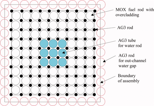
The lattice configuration of the test assemblies except those for the time-elapsed reference core simulated the hot operating condition with the in-channel void fraction of 40% by adjusting a local moderator-to-fuel ratio distribution with properly selecting the specifications of AG3 (Aluminum alloy) overcladdings for the test MOX rods, AG3 rods at the corners of the MOX cells, AG3 tubes for the water rods and AG3 rods in the out-channel gaps. shows a configuration of the fuel assembly with the in-channel void fraction of 40% in the test region. The AG3 rods are explicitly shown in ; however, the overcladdings and AG3 tubes are not shown in . The specifications of the assemblies in the driver region were mockup 9 × 9 MOX assemblies in a cold state of a BWR core, which was selected to make the cores critical by compensating various reactivities in the test region.
2.2. Measurements
The critical mass was measured for each core. After the number of MOX rods in the driver region was adjusted to make the core critical, the pilot rod was withdrawn to make the core slightly supercritical. The doubling time was measured to determine the excess reactivity. shows the measured doubling time and the excess reactivity in the units of dollar.
The fission rate distributions in the core radial and axial directions were measured by integral gamma scanning. Germanium gamma ray detectors were used to count gamma rays emitted from a specific axial part of the fuel rod after a short period irradiation. Integral counts of gamma ray pulses larger than 550 keV were used to obtain the relative fission rates. A middle part of the fuel rod was measured for the measurement of the core radial fission rate distributions. For the axial fission rate distribution, the integral gamma scanning measurement was applied with about 1-cm step in the axial direction of the fuel rod. The fission rate distribution measurement was applied to the control blade, Gd2O3-UO2 rod and 10 × 10 cores and not applied to the UO2 rod and time-elapsed reference cores as shown in . In the core radial fission rate measurement of the Gd2O3-UO2 rod core, gamma ray spectrometry on a specific gamma ray (1.596 keV) from the decay of 140La was applied to represent MOX, UO2, and Gd2O3-UO2 rods. It was necessary to obtain the relative fission rate distribution in assemblies mix-loaded with MOX, UO2, and Gd2O3-UO2 fuel rods. The method was also applied to the 10 × 10 core to obtain the whole core radial fission rate distribution including the test and driver region by correlating the relative fission rates independently measured for the test and driver regions by integral gamma scanning. The Appendix describes the radial locations of the measured fuel rods and the measurement results of the core radial fission rate distributions.
Table 3. Fission rate distribution measurements and measured buckling values.
Axial fission rate distribution measurement was applied to two MOX rods in the test region and one MOX rod in the driver region for the control blade and Gd2O3-UO2 rod cores and two MOX rods in the test region for the 10 × 10 core. The measured axial distributions were used to obtain the core axial buckling by fitting the measured data with a cosine function. shows the average values of the three or two measurement values with the measurement errors.
3. Analysis of experimental cores
3.1. Analytical method
Neutronics analysis was applied to the experimental cores to obtain the calculated results of the effective neutron multiplication factors k eff's and core radial fission rate distributions. One of the analysis systems was deterministic calculation methods, which are commonly used in LWR core design. The other was a continuous energy Monte Carlo calculation method for obtaining the reference calculation results to be compared with those of the deterministic calculation methods.
3.1.1. Deterministic calculations
The calculations were performed in two steps, cell calculations followed by core calculations. Two dimensional infinite square lattice calculations were applied to the component cells such as the fuel cells each typically consisting of a fuel pellet, a fuel cladding, an overcladding, water and parts of an AG3 rod located at four cell corners. A collision probability module of SRAC [Citation13] was used in the lattice calculations with the 107-neutron-energy-group library based on the evaluated nuclear data library JENDL-3.3 [Citation14], and the resonance cross-sections obtained by the ultra-fine-energy-group-calculation module PEACO [Citation13]. A thermal cutoff energy was set to be 1.8554 eV, which was determined so that an infinite neutron multiplication factor obtained using SRAC coupled with PEACO agreed to that obtained using MVP [Citation15] for a MOX fuel cell consisting of the MOX fuel rod of the total Pu content of 7.0 wt% and a moderator of water in the analysis study of the MISTRAL program [Citation16].
A cell calculation for the out-channel gap, into which the control rod was inserted, was performed with a multi-cell model indicated in Ref. [Citation13]. shows the specific model in the present study, where the control rod structures were exactly treated, and the fuel rod cells and the out-channel gap located in the opposite side of the out-channel gap with the control rod were homogenized in terms of the atomic densities. The row of MOX fuel rods in the model were set to the second row of MOX fuel rods from the outermost side of the MOX assembly facing the control blade. Sensitivity analysis was also performed with different rows of MOX fuel rods. The effect of the different rows of MOX fuel rods on the effective neutron multiplication factor k eff of the core was 0.18 and 0.02% Δk, for a diffusion and transport calculations, respectively. The effect on the fission rate distributions will be discussed in the later section.
Figure 5. Multi-cell model for out-channel gap inserted with a cruciform control blade. Note: Ex. MOX 5.0wt%: homogenized cell of MOX rod of 5.0 (total Pu) wt%, moderator and structures.

In the cell calculation of a Gd2O3-UO2 rod cell in the Gd2O3-UO2 rod core, an infinite multi-cell model of 3 × 3 fuel rods was adopted, where the rod of the center position was the relevant Gd2O3-UO2 rod and eight neighboring rods were the MOX rods of 7.0 (total Pu) wt%, which were loaded in the driver region. The aim of this model is for taking into account the spectrum interaction from the MOX rods on the Gd2O3-UO2 rod in the process to generate the nuclear constants for the core calculation. As seen in , the Gd2O3-UO2 are adjoined by various cells such as MOX rods of 5.0, 8.5, and 11.5 (total Pu) wt%, Gd2O3-UO2 rods, the water rods and water gaps so that the selection of the neighboring rods was a tentative one and more elaborate treatment will be discussed in the later section. After the cell calculations, the effective cross-sections were spatially averaged and also collapsed into 16 energy groups [Citation16] for each cell.
In the core calculations, the diffusion calculation code CITATION [Citation17] was used with the 16 neutron energy groups under two and/or three dimensional geometries. The transport calculation code DANTSYS [Citation18] were also applied to the core calculations. In the transport calculations, the 16 neutron energy groups and the P0–S8 approximation were adopted.
In order to convert the unit of excess reactivity from dollars to Δk, an effective delayed neutron fraction was calculated for each core. This calculation adopted 21 neutron energy groups based on JENDL-3.3 and a three-dimensional geometrical model with CITATION. The 21 neutron energy groups were adopted to take into account the dominant neutron energy range of delayed neutrons from 40 keV to 2.0 MeV.
The minimum thickness of the water reflector in the core radial direction was from 15 cm for the control blade core to 27 cm for the 10 × 10 assembly core. The core radial geometrical model took into account the water reflector in the outside of the driver region up to the inner diameter of 115.4 cm of the core inner tank. Two kinds of treatments were applied to the axial modeling. The first one was a two dimensional geometrical model where the axial leakage of neutrons was calculated by applying the measured axial buckling values shown in . The second was the three dimensional geometrical model, which covers from the bottom core grid to the top core grid. The thickness of the water reflector, which was measured from the end of the effective part of the fuel rod to the surface of the bottom core grid and the bottom surface of the top core grid, was 13 cm and 15 cm in the bottom and top of the core, respectively. Both diffusion and transport calculations were basically applied to a one-fourth core model (except for the UO2 and Gd2O3-UO2 rod cores) since the core basically had a one-fourth symmetry, and small effects of a pilot rod and a fission chamber in the driver region can be neglected. In the radial model, two meshes were assigned to each cell including a fuel rod, and four meshes were assigned to each out-channel water gap, since a thermal neutron flux steeply changes in the out-channel water gap. The number of meshes in this mesh model was also applied to the out-channel water gap including the control blade. A mesh size in a water reflector region in the outside of the driver region was set to the same for the cell including a fuel rod. In the axial geometrical model, a mesh size in a fuel effective part was set to be 1 cm, and slightly larger mesh sizes were assigned to the reflector regions.
3.2.2. Monte Carlo calculations
The MVP code [Citation15] was used for continuous energy Monte Carlo calculations, and the nuclear data libraries were prepared from the evaluated nuclear data libraries of JENDL-3.3 [Citation14], JENDL-4.0 [Citation19], ENDF/B-VI.8 [Citation20], ENDF/B–VII [Citation21], and JEFF-3.1 [Citation22]. The three dimensional geometrical model included the core and water reflector inside the core tank in the core radial direction. The core axial model covers the same region as the deterministic calculations. The model explicitly simulated the fuel rods and other components including guide tubes for the pilot rod and the fission chamber. In order to obtain smaller calculation statistical errors in radial fission rate distributions, a whole effective fuel part was regarded as a tally region. In the radial direction, two or four fuel rods at symmetrical positions were combined as a single tally region. In this treatment, the small effect of the pilot rod and fission chamber, which asymmetrically located in the driver region, on the radial fission rate distribution in the test region was neglected.
Two thousand three hundred batch samplings with 20,000 neutron histories per batch were performed, and the initial 300 batches were skipped from the statistical process, which were selected to obtain the statistical errors less than 0.0002 Δk in the k eff's.
3.2. Analysis results and discussion
3.2.1. Criticality
Effective neutron multiplication factor k eff was calculated for each core at the critical mass measurement, which had small excess reactivity. In order to obtain critical k eff, the excess reactivity was subtracted from it. The excess reactivity in the unit Δk/k was obtained from the measured excess reactivity in the unit dollar using the calculated effective delayed neutron fraction, which is shown in . Here, the excess reactivity was approximately regarded as that in the unit Δk since k eff was very close to 1.0. summarizes the critical k eff's of the adopted calculation methods for the five cores. schematically shows those calculated using the deterministic and Monte Carlo calculation methods based on JENDL-3.3 against the number of MOX rods in the driver region; shows those calculated using MVP with the different nuclear data libraries. The statistical errors in the MVP calculations are far smaller than the sizes of symbols in the figure. and also include the calculated k eff's for other critical cores in FUBILA reported in Ref. [Citation9] for comparison. As seen in and , the calculated critical k eff's for the five cores are generally consistent with those in Ref. [Citation9]. Discussions are following.
Figure 6. Critical k eff's calculated with JENDL-3.3 for the FUBILA cores. Note: Critical k eff's of bold–italic faced cores show the present results and others those in Ref. [Citation9].
![Figure 6. Critical k eff's calculated with JENDL-3.3 for the FUBILA cores. Note: Critical k eff's of bold–italic faced cores show the present results and others those in Ref. [Citation9].](/cms/asset/b6cc126b-1c2e-4054-9785-8fd5172c1cc5/tnst_a_636553_o_f0006g.jpg)
Figure 7. Critical k eff's calculated by MVP. Note: Critical k eff's of bold–italic faced cores show the present results and others those in Ref. [Citation9].
![Figure 7. Critical k eff's calculated by MVP. Note: Critical k eff's of bold–italic faced cores show the present results and others those in Ref. [Citation9].](/cms/asset/6befc032-64f3-4332-b93e-ad996ae248c9/tnst_a_636553_o_f0007g.jpg)
Table 4. Critical k eff of the FUBILA cores.
3.2.1.1. Deterministic calculations
The critical k eff's of the diffusion calculations (CITATION) with the JENDL-3.3-base library for the five cores are from 0.997 to 1.001, which are systematically lower than the Monte-Carlo calculations (MVP) by −0.3 to −0.5% Δk. This is attributed to the calculation model of the diffusion calculation model adopted in the present study. Those of the transport calculations (TWODANT and THREEDANT) are from 1.000 to 1.003, which are close to those of the Monte Carlo calculations. It indicates that the transport calculation model of the present study gives accurate k eff's, which are close to those of the Monte Carlo calculations. These observations are consistent with those in Ref. [9]. This indicates that the features applied in the five cores, i.e. the B4C control blade, the UO2 and Gd2O3-UO2 fuel rods in MOX assemblies, the 10 × 10 MOX assemblies, and the time-elapsed MOX core do not introduce excess calculation errors in the reactivity calculations of the present deterministic calculation methods.
3.2.1.2. Trend with number of MOX rods in driver region
A general trend of k eff's with the number of MOX rods in the driver region is seen in those of the five cores in both deterministic and Monte Carlo calculations. The correlation of the trend with the fuel compositions in the MOX rods was discussed in Ref. [Citation9] on the uncertainty in the thermal and/or resonance cross-sections of 241Am and 241Pu. Beside this general trend, it is also observed in and that there are small divergences in k eff's from the general increasing trend for the 10 × 10, UO2 rod, and Gd2O3-UO2 rod cores. This would be related to the higher Pu contents in the 10 × 10 assemblies and the existence of UO2 rod and Gd2O3-UO2 rods in the UO2 rod and Gd2O3-UO2 cores. It is typically seen in the results of MVP based on JENDL-3.3 in that the increase in the k eff's from the 9 × 9 reference to time-elapsed cores is larger than the general increase with the number of MOX rods in the driver region. This would be due to the fact that the increase in the k eff's is caused by time-elapsed effect in the Pu isotopic composition of the MOX rods in the test region in 17 months in addition to the change in the number of MOX rods in the driver region.
3.2.1.3. Nuclear data library
The critical k eff's of the Monte Carlo calculations range from 1.000 to 1.007 as seen in . The values based on JENDL-3.3, JENDL-4.0, and JEFF-3.1 are closely plotted; on the other hand, those based on ENDF/B-VI.8 and ENDF/B-VII disperse from them. The k eff's based on ENDF/B-VII show from 0.5 to 0.6% Δk higher than those based on ENDF/B-VI.8. It is noted that the k eff's with JEFF-3.1 show the smallest trend against the change in the number of the MOX rods in the driver region.
Blaise et al. [Citation6] have reported the critical k eff's calculated by the continuous energy Monte Carlo calculation code TRIPOLI-4.5 for the 9 × 9 reference, 40% void, and 70% void cores of the FUBILA program. The critical k eff's are 1.001 to 1.002 for JEFF-3.1 and 1.0045 to 1.007 for ENDF/B-VII. These results agree with those of the present calculations of MVP based on the same nuclear data libraries for all the FUBILA critical cores shown in .
The critical k eff's of JENDL-3.3 and JENDL-4.0 show close results, which was also reported in Ref. [Citation24] for those of the 9 × 9 reference core of FUBILA. One of major difference in cross-sections relevant to the core analysis of the FUBILA program between JENDL-3.3 and JENDL-4.0 is those of 241Am. The thermal capture cross-section and resonance integral cross-sections of 241Am in JENDL-4.0 are larger by 7 and 9% than those in JENDL-3.3, respectively. This makes the k eff's for JENDL-4.0 smaller than those for JENDL-3.3. The changes would be almost compensated by the other increasing effect for the k eff's from the other differences between JENDL-3.3 and JENDL-4.0 such as decreases in the thermal capture cross-sections of 238U and the resonance integral cross-sections of 239Pu. It should, however, be confirmed in the further study.
3.2.2. Core radial fission rate distribution
3.2.2.1. Control blade core
and show the relative deviations of the calculated radial fission rates from the measured results in the test region as defined (Calculated fission rate–measured fission rate)/(measured fission rate) × 100. The calculated results are those of the diffusion calculation (CITATION-2D) and the transport calculation (TWODANT) based on JENDL-3.3. schematically shows the comparison between the calculated results of CITATION-2D and the measurements in the diagonal direction of the test region. The measurement errors of 1.2% are also attached to the measurements. also shows the root mean squares (RMSs) of the relative deviations, and the maximum (Max) and minimum (Min) deviations. includes those of the results calculated by using MVP based on JENDL-3.3 [Citation4]. The table also shows the measurement errors which were evaluated using the differences in the measured radial fission rates on the fuel rods at the geometrically symmetrical locations in the test region [Citation4]. Here, the deviations were defined as those from the average fission rates of the two fuel rods at the geometrically symmetrical locations. The RMSs of the deviations were calculated and converted to the measurement error of the fission rate measurement. The analysis errors slightly depend on the types of the analysis methods. The general trends in the errors are represented by the parameters shown in . The RMS of the diffusion calculation is two times of the measurement error, that of the transport calculation 1.6 times, and that of the Monte Carlo calculation 1.4 times. In the deterministic calculations of the control blade core, the differences in the RMSs were less than 0.1% for adopting different rows of MOX fuel rods in the multi-cell model for the out-channel gap inserted with the control blade.
Figure 8. Deviation of calculated radial fission rates of CITATION-2D calculation from measurements for the test region of the control blade core. Note: Deviation (%): (calculated fission rate −measured fission rate)/(measured fission rate) × 100.
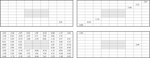
Figure 9. Deviation of calculated radial fission rates of TWODANT calculation from measurements for the test region of the control blade core. Note: Deviation (%): (calculated fission rate −measured fission rate)/(measured fission rate) × 100
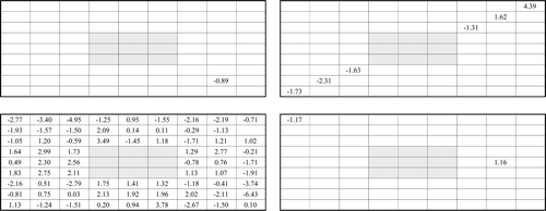
Table 5. Root-mean-square (RMS), maximum (Max) and minimum (Mini) values of (calculated–measured)/measured in % for radial fission rates in the test region.
3.2.2.2. Gd2O3-UO2 core
and present the relative deviations of the calculated radial fission rates from the measurements for the fuel rods in the test region. The calculated results are those for CITATION-2D and TWODANT based on JENDL-3.3. also shows the root mean squares (RMSs) of the relative deviations, and the maximum (Max) and minimum (Min) deviations, where those of the results calculated using MVP based on JENDL-3.3 [Citation4] are also included. and indicate systematic deviations unique to the types of fuel rods. The average values of the deviations for the fuel rod types are shown in , which include calculated results using MVP based on JENDL-3.3. The figures and indicate that the diffusion calculation systematically underestimates the fission rates of UO2 rods, and the transport and Monte Carlo calculations do those of Gd2O3-UO2 and UO2 rods. When the calculated results of the deterministic methods were compared with those of the Monte Carlo calculation as the reference calculations, the diffusion calculation underestimates the fission rates of UO2 rods by 3% and overestimates those of Gd2O3-UO2 rods by 4%; the transport calculation overestimates those of UO2 rods by 2%. Further analysis was performed to know possible causes of the systematic trends.
Figure 10. Comparison between calculated fission rates of CITATION-2D and measurements in the diagonal direction of the test region of the control blade core. Note: The average values of fission rates are normalized to 1.0.
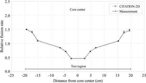
Figure 11. Deviation of calculated radial fission rates of CITATION-2D calculation from measurements for the test region of the Gd2O3-UO2 core [Citation12]. Note: Deviation (%): (calculated fission rate −measured fission rate)/(measured fission rate) × 100. Notation: Brown: UO2 rod, dark blue: Gd2O3-UO2 rod, light blue, white and yellow: MOX rods.
![Figure 11. Deviation of calculated radial fission rates of CITATION-2D calculation from measurements for the test region of the Gd2O3-UO2 core [Citation12]. Note: Deviation (%): (calculated fission rate −measured fission rate)/(measured fission rate) × 100. Notation: Brown: UO2 rod, dark blue: Gd2O3-UO2 rod, light blue, white and yellow: MOX rods.](/cms/asset/d327ec40-60cb-4c76-9918-2e081df04909/tnst_a_636553_o_f0011g.jpg)
Figure 12. Deviation of calculated radial fission rates of TWODANT calculation from measurements for the test region of the Gd2O3-UO2 core [Citation12]. Deviation (%): (calculated fission rate −measured fission rate)/(measured fission rate) × 100. Notation: Brown: UO2 rod, dark blue: Gd2O3-UO2 rod, light blue, white and yellow: MOX rods.
![Figure 12. Deviation of calculated radial fission rates of TWODANT calculation from measurements for the test region of the Gd2O3-UO2 core [Citation12]. Deviation (%): (calculated fission rate −measured fission rate)/(measured fission rate) × 100. Notation: Brown: UO2 rod, dark blue: Gd2O3-UO2 rod, light blue, white and yellow: MOX rods.](/cms/asset/4a7a6e10-946c-42b7-b102-4dbbc0503414/tnst_a_636553_o_f0012g.jpg)
Table 6. Average deviation of calculated fission rates from measurements as (calculated–measured)/measured in % for the Gd2O3-UO2 rod core.
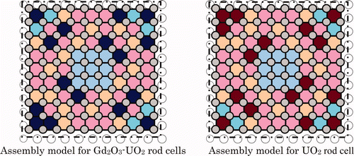
In order to improve the cell calculations of the cells of UO2 and Gd2O3-UO2 rods, infinite assembly models of the Gd2O3-UO2 rod loaded assembly and the UO2 rod loaded assembly shown in were adopted, which was aimed at taking into account the influence on the neutron spectrum calculation of the UO2 and Gd2O3-UO2 rod cells from adjoining cells with different characteristics. The cell calculations for the MOX rod cells remained the infinite one rod cell calculations. The deviations of the calculations with the improved lattice calculations from the measured fission rates are shown in . The significant improvement is seen in the deviations of the UO2 rods. On the other hand, the change in the Gd2O3-UO2 rods is small since the original lattice calculation model adopted the 3 × 3 multi-cell calculations in order to take into account the interaction effect from neighboring MOX rods, even though the selection of the MOX rods adjoining to the Gd2O3-UO2 rod was a tentative one in the multi-cell mode. It is still observed that there exist the general deviations of the calculated fission rates of the UO2 and Gd2O3-UO2 rods in the diffusion and transport calculations from the Monte Carlo calculations even after improving the cell calculation. That would be due to modeling errors in the deterministic calculation methods.
Figure 13. Infinite assembly models in lattice calculations for Gd2O3-UO2 rod cells and UO2 rod cells in the Gd2O3-UO2 Core. Note: Notation should be referred to Figure 2.
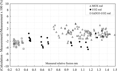
It was assumed that the relatively large underestimation of about 4% in the fission rates for the Gd2O3-UO2 rods and about 2% for the UO2 rods in the Monte Carlo calculations was caused by the uncertainties in the nuclear data libraries. This trend was almost common among the nuclear data libraries as shown in . New measurements of thermal and resonance cross-sections of Gadolinium have been reported by Leinweber et al. [Citation23]. Their significant findings were that the thermal (2200 m/s) capture cross-section of 157Gd was measured to be 11% smaller than that calculated from ENDF/B-VI [Citation20]. Referring to the measured data, Jatuff et al. [Citation25] have reported that the new cross-sections of gadolinium isotopes reduce the discrepancies in comparison between the measurement and neutronics analysis on the rod-by-rod fission rates and modified conversion ratios obtained in the critical experiments at the PROTEUS critical facility. In the process of evaluation work of JENDL-4.0, a temporary nuclear data library of MVP [Citation26], was prepared, which replaced the cross-sections of 157Gd by the new measurement data. The calculated results of MVP with the temporary nuclear data library are shown in and . shows the deviations of the calculated fission rates from the measurements against the measured fission rates. They show that the degree of the underestimation of the fission rates by the MVP calculations for the Gd2O3-UO2 rods is reduced from −4.09% to −2.59%, which makes the degree of the underestimation similar for both UO2 and Gd2O3-UO2 rods.
Figure 14. Deviation of calculated radial fission rates of MVP calculation with 157Gd-modified JENDL-3.3 from measurements for the test region of the Gd2O3-UO2 core.
shows the calculated k eff of MVP with the temporary nuclear data library of 157Gd. The effect of the temporary nuclear data library on k eff was +0.04 ± 0.02% Δk and not significant due to a small number of Gd2O3-UO2 rods in the core. It should be noted that the finalized JENDL-4.0 adopted the resonance parameters based on the new measurements, and also background cross-sections aimed at making the capture cross-section at 2200 m/s of JENDL-4.0 coincide with that of JENDL-3.3 [Citation19,Citation24].
About remaining deviation in C/Es between the MOX and UO2 fuel rods, Chauvin et al. [Citation27] and Nagaya et al. [Citation28] have also reported that their neutronics analysis results overestimate the measured fission rates of the MOX fuel rod region in the UO2–MOX mixed cores of the EPICURE and VENUS-2 programs. The overestimation of the fission rates for the MOX rods, which means underestimation of the UO2 and Gd2O3-UO2 rods on the other side, would be related to uncertainties in nuclear data libraries.
3.2.2.3. 10 × 10 MOX assembly core
and show the relative deviations of the calculated radial fission rates from the measurements. The calculated results are those of the diffusion calculation (CITATION-3D) and the transport calculation (THREEDANT) based on the nuclear data library JENDL-3.3. schematically shows the comparison between the calculated results of CITATION-3D and the measurements about the fission rates in the diagonal direction. also shows the root mean squares (RMSs) of the relative deviations, and the maximum (Max) and minimum (Mini) deviations, where those of the results calculated by using MVP based on JENDL-3.3 [Citation4]. are also included. The analysis errors slightly depend on the analysis methods, and the general trend is represented by the parameters shown in . The RMS of the diffusion calculation is 1.8 times of the measurement error, and those of the transport and Monte Carlo calculations are same order. The RMSs of the 10 × 10 MOX assembly core is comparable with those of the 40% void core (9 × 9 assembly) in Ref. [Citation9], i.e. 1.81, 1.33, and 1.08% for the diffusion, transport and Monte Carlo calculation methods and 1.0% for the measurement error, which indicate that the higher Pu content assemblies with the 10 × 10 lattice do not introduce extra calculation errors in the fission rate calculation for the present deterministic and Monte Carlo calculation methods.
Figure 15. Deviation of calculated radial fission rates of CITATION-3D calculation from measurements for the 10 × 10 MOX assembly core.
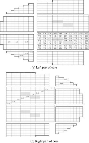
Figure 16. Deviation of calculated radial fission rates of THREEDANT calculation from measurements for the 10 × 10 MOX assembly core.
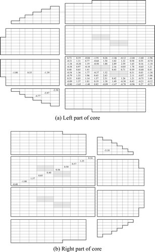
Figure 17. Comparison between calculated fission rates of CITATION-3D and measurements in the diagonal direction of the 10 × 10 MOX assembly core. Note: The average values of fission rates are normalized to 1.0.
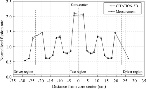
Figure A1. Measured relative radial fission rate distribution in the control blade core [Citation4]. Note: The average value of measured 81 fuel rods in the test region is 1.0 and that of 7 fuel rods in the driver region 1.0.
![Figure A1. Measured relative radial fission rate distribution in the control blade core [Citation4]. Note: The average value of measured 81 fuel rods in the test region is 1.0 and that of 7 fuel rods in the driver region 1.0.](/cms/asset/ab4132e5-cccf-4817-9d75-1bd18a2d6210/tnst_a_636553_o_f0018g.gif)
Figure A2. Measured relative radial fission rate distribution in the test region of the Gd2O3-UO2 rod core [Citation4]. Note: The average value of measured 167 fuel rods in the test region is 1.0.
![Figure A2. Measured relative radial fission rate distribution in the test region of the Gd2O3-UO2 rod core [Citation4]. Note: The average value of measured 167 fuel rods in the test region is 1.0.](/cms/asset/4c53a99a-2975-4338-98d0-de8c1cef97ba/tnst_a_636553_o_f0019g.gif)
Figure A3. Measured radial fission rate distribution in the 10 × 10 MOX assembly core [Citation4]. Note: The average value of measured 109 fuel rods in the test region is 1.0.
![Figure A3. Measured radial fission rate distribution in the 10 × 10 MOX assembly core [Citation4]. Note: The average value of measured 109 fuel rods in the test region is 1.0.](/cms/asset/a54c6e88-25a4-4e88-9b47-ff9f5fbb4959/tnst_a_636553_o_f0020g.gif)
4. Conclusions
Major findings in the neutronics analysis of the control blade, UO2 rod, Gd2O3-UO2 rod, 10 × 10 MOX assembly and time-elapsed reference cores in the FUBILA program are the following. The k eff's of the diffusion calculations in the present study are lower than those of the Monte-Carlo calculations by −0.3 to −0.5% Δk. On the other hand, those of the transport calculations are close to those of the Monte Carlo calculations, which means the model of the present transport calculations is accurate enough to calculate the k eff's of the FUBILA critical cores. The Monte Carlo calculations based on the major nuclear date libraries show the k eff's ranging from 0.999 to 1.007. The differences in the k eff's between JENDL-3.3 and JENDL-4.0 are small; on the other hand, those of ENDF/B-VII are larger than those of ENDF/B-VI.8 by 0.5 to 0.6% Δk.
The analysis of the core radial fission rates indicates that the RMSs of differences between the calculated and measured core radial fission rates are 2 to 3%, 1 to 2%, and 1 to 2% for the diffusion, transport, and Monte Carlo calculations, respectively, which are one to three times larger than the measurement errors. They are generally smaller in the order of the Monte Carlo, transport and diffusion calculations under the present analysis models. The extended study on the Gd2O3-UO2 core indicates that taking into account the adjoining cells in the cell calculations of the UO2 fuel rods makes the radial fission rates of the UO2 fuel rods in the deterministic calculations close to those in the Monte Carlo calculations. Applying the newly measured thermal and resonance cross-sections of 157Gd in the Monte Carlo calculations also improves the agreement between the Monte Carlo calculations and the measurements for radial fission rates of the Gd2O3-UO2 rods in the Gd2O3-UO2 rod core.
Acknowledgments
The authors wish to thank the experimental team lead by Drs. P. Fougeras and P. Blaise for the implementation of the FUBILA experiments in the EOLE critical facility.
Notes
1. Full MOX core physics experiments of BWR Initiated for Lattice analysis method verification and improvement.
2. Including 241Am.
3. Including 241Am.
References
- Nuclear Safety Commission of Japan . 1999 . Full Core Loading of Mixed Oxide Fuels in Advanced Boiling Water Reactors , Nuclear Safety Commission of Japan . [in Japanese]
- Japan Nuclear Energy Safety Organization (JNES) . 2007 . Experimental Results and Analysis of 40 and 70% Void Cores in a BWR Full MOX Core Physics Experimental Program , JNES-SS-0708, Japan Nuclear Energy Safety Organization (JNES) . [in Japanese]
- Japan Nuclear Energy Safety Organization (JNES) . 2007 . Experimental Results and Analysis of a 9 × 9 Reference Core in a BWR Full MOX Core Physics Experimental Program , JNES-SS-0622, Japan Nuclear Energy Safety Organization (JNES) . [in Japanese]
- Japan Nuclear Energy Safety Organization (JNES) . 2009 . Full MOX BWR Core Physics Experiment – Experimental and Analysis Results of Critical Cores and Reactivity Measurements , JNES-SS-0905, Japan Nuclear Energy Safety Organization (JNES) . [in Japanese]
- Blaise , P , Vagrio-Gaudard , C Vidal , J. F. Deterministic Modeling of 100%MOX ABWR Lattices with Increasing Void Fraction: Validation of the REL2005 Code Package on FUBILA Experimental Program . Proceedings of International Conference on ICAPP ‘09 . May 10–14 2009 . Paper No. 9290
- Blaise , P and Thiollay , N . 2010 . Monte Carlo modelling of increasing void fraction in 100% MOX ABWR: Lessons drawn from the FUBILA program . J. Nucl. Sci. Technol , 47 : 558 – 569 .
- Yamamoto , T , Kikuchi , S Kawashima , K . FUBILA: Core Physics Experimental Program Aimed at Validation of Core analysis Method for High Burn-Up BWR Full MOX Cores . Proceedings of International Conference on GLOBAL 2005 . October 9–13 2005 . Paper No. 092
- Yamamoto , T , Kikuchi , S Kawashima , K . Experimental Results and Analysis of Core Physics Experiments, FUBILA, for High Burn-Up BWR Full MOX Cores . Proceedings of International Conference on the PHYSOR 2006 . September 10–14 .
- Yamamoto , T , Sakai , T Ando , Y . 2011 . Neutronics analysis of full MOX BWR core simulation experiments FUBILA . J. Nucl. Sci. Technol , 48 : 398 – 420 .
- Yamamoto , T , Ando , Y and Liem , P. H . Analysis of Core Physics Experiment on BWR 10 × 10 MOX Fuel Assemblies . Proceedings of International Conference on PHYSOR 2010 . May 9–14 .
- Yamamoto , T , Ando , Y Sakai , T . 2009 . Analysis of reactivity measurements in core physics experiments on full-MOX BWR . J. Nucl. Sci. Technol , 46 : 599 – 612 .
- Yamamoto , T , Ando , Y and Sakai , T . Analysis of Core Physics Experiments on MOX Assemblies Loaded with Gd2O3-UO2 and UO2 Rods . Proceedings International Conference on ICAPP ‘09 . May 10–14 2009 . Paper No. 9290
- Okumura , K , Kugo , T Kaneko , K . 2007 . SRAC2006: A Comprehensive Neutronic Calculation Code system, JAERI-Data/Code 2007–004 , Japan : Atomic Energy Research Institute (JAERI) .
- Shibata , K , Kawano , T Nakagawa , T . 2002 . Japanese evaluated nuclear data library version 3 revision-3: JENDL-3.3 . J. Nucl. Sci. Technol , 39 : 1125 – 1126 .
- Nagaya , Y , Okumura , K Mori , T . 2005 . MVP/GMVP II: General Purpose Monte Carlo Codes for Neutron and Photon Transport Calculations Based on Continuous Energy and Multigroup Methods , JAERI-1348, Japan Atomic Energy Research Institute (JAEA) .
- Kanda , K , Yamamoto , T Matsuura , H . 1998 . MOX fuel core physics experiments and analysis – aiming for Plutonium effective use . Nihon-Genshiryoku-Gakkai Shi (J. At. Energy Soc. Jpn.) , 40 : 834 – 854 . [in Japanese]
- Fowler , T. B. , Vondy , D. R. and Cummingham , G. W. 1969 . Nuclear Reactor Analysis Code: CITATION, ORNL-TM-2496 , Oak Ridge National Laboratory (ORNL) .
- Alcouffe , R. E. , Baker , R. S. Brinkley , F. W. 1995 . DANTSYS: A Diffusion Accelerated Neutral Particle Transport Code System , LA : LA-12969-M, Los Alamos National Laboratory .
- Shibata , K , Iwamoto , O Nakagawa , T . 2011 . JENDL-4.0: A new library for nuclear science and engineering . J. Nucl. Sci. Technol , 48 : 1 – 30 .
- Rose , P. F. and C.L . 1997 . Dunford, ENDF-102 data formats and procedures of the evaluated nuclear data file ENDF-6, BNL-NCS-44945, Rev. 2 , Brookhaven National Laboratory (BNL) .
- Chadwick , M. B. Oblozinsky , P . 2006 . ENDF/B-VII.0: Next generation evaluated nuclear data library for nuclear science and technology . Nucl. Data Sheets , 107 : 2931 – 3059 .
- Koning , A , Forrest , R Kellett , M . 2006 . The JEFF-3.1 Nuclear Data Library JEFF Report 21
- Leinweber , G , Barry , D. P. Trbovich , M. J. 2006 . Neutron capture and total cross-section measurements and resonance parameters of Gadolinium . Nucl. Sci. Eng , 154 : 261
- Chiba , G Okumura , K . 2011 . JENDL-4.0 benchmarking for fission reactor applications . J. Nucl. Sci. Technol , 48 : 172 – 187 .
- Jatuff , F , Perret , G Murphy , M . Impact of Newly-Measured Gadolinium Cross Sections on BWR Fuel Rod Reaction Rate Distributions . Proceedings of International Conference on the PHYSOR 2008 . September 14–19 .
- Okumura , K . 2008 . private communication, December
- Chauvin , J. P. , Cabrillat , J. C. Fougeras , P . EPICURE: Synthesis of an Experimental Programme Devoted to the Validation of the Calculation Scheme for the Pressurized Water Reactor Recycling MOX Fuel . Proceedings of International Conference on the PHYSOR ‘96 . September 16–20 .
- Nagaya , Y , Okumura , K and Mori , T . Analysis of VENUS-2 MOX Core Measurements with a Monte Carlo Code MVP . Proceedings of International Conference on the PHYSOR 1996 . September 16–20 .
Appendix
The measured radial fission rate distributions are shown in Figure A1 for the control blade core [Citation6], Figure A2 for the Gd 2O3-UO2 core [Citation6], and Figure A3 for the 10 × 10 MOX assembly core [Citation6]. In order to estimate measurement errors in the radial fission rate distribution, the fission rates of fuel rods were compared with those of fuel rods at symmetrical positions in the left-bottom fuel assembly of the test region. It was found that the differences between them were generally larger than the counting statistical errors in the integral gamma scanning, which were from 0.2 to 0.3%. Using the information about the symmetry of fission rates, the study of measurement errors was performed to assess the overall measurement errors [Citation6]. The estimated measurement errors of the radial fission rates were from 1.2 to 1.3% as shown in in the text. The measurement errors of the Gd2O3-UO2 and 10 × 10 MOX assembly cores include the measurement errors in the determination of the radial fission rate distributions using the spectrometry on the specific gamma ray (1.596 keV) from the decay of 140La.
