
Abstract
Quality Assurance/Quality Control (QA/QC) requirements and the test results generated through the requirements have been the catalysts to the development of many innovations and improved practices used by contractors today to install bored piles/ drilled shafts (BP/DS). While the need for sophisticated QA/QC practice is acknowledged around the world, practices applied for these kinds of deep foundations differ significantly owing to local, state or federal requirements. This paper reviews QC code and standard guidelines frequently implemented in North America and Europe, along with technological developments over the past decade to assure the installation of a high-quality BP/DS. An overview of common non-destructive and destructive test methods is provided and the implementation in both continents evaluated through survey results.
Introduction
While the need for quality management (QM) in the construction of deep foundations is recognised around the world, differing opinions exist as to what a QM programme is, and what distinguishes Quality Assurance (QA) from Quality Control (QC). Simultaneously, with the evolution of the bored pile/drilled shaft (BP/DS) industry, new technology is continuously introduced in North America and Europe to help ensure the quality and performance. Considering the differences in the market forces between North America and Europe, it is to be expected that the advent of a new technology differs between these markets. This paper discusses similarities and differences in QA/QC practice on both continents and reviews the technologies used to assist foundation practice and ensure foundation performance in North America and Europe. For the purposes of the ensuing discussion, the following distinctions are used:
QM is considered a cooperative programme involving all parties throughout the site exploration, design, construction, testing and acceptance processes. Ideally, it also includes the architect and the structural engineer, where applicable, to ensure that all parties understand the design intent, the site conditions and the factors affecting the construction of the selected foundation type.
QA is referred to as documented procedures for ensuring quality in both the design and the construction processes, with the purpose of eliminating flaws and defects. QA is a QM tool utilised by both the design and the construction teams. Much of the design and construction process for bored pile/drilled shaft foundation construction involves tools and techniques for ensuring the quality of materials and the quality and accuracy of workmanship during the construction process, thus providing QA. The techniques applied during construction are evaluated in the ‘Tools of the Trade’ section of this paper and include visual inspection from the top of the excavation, visual inspection by downhole entry, Koden monitor (Ultrasonic Caliper), mechanical caliper, plumb bob, downhole camera, shaft inspection device (SID) and base grouting. These tools enable the contractor to ensure shaft verticality, the shape of the shaft as well as the cleanliness of the base of the excavation, whether drilled ‘in the dry’ or under a drilling fluid. QA is typically the responsibility of the contractor, and is generally performed by the contractors' own personnel, both in Europe and in the US, although the contractor may also use an inspection firm, especially for more advanced QA techniques.
QC is defined as the verification of foundation integrity and capacity after construction and utilises technologies for verifying the quality of constructed foundations by locating and identifying flaws in materials and/or geometry, or by employing techniques to assess known flaws in order to determine if they are considered unacceptable defects in the finished product, and aid in the design of acceptable repairs. QC is a quality verification methodology typically performed by a third party after completion of the BP/DS foundation. Practices for engaging the QC firm vary, but relevant survey responses indicated that for both public and private projects in Europe, the QC firm is typically engaged by the contractor. In North America, QC for public (state or municipal) projects is typically performed by the owner’s personnel, or a third party engaged by the owner. For private projects, the owner usually engages a third-party QC firm, but occasionally the contractor engages them.
Most of the commonly practised methods are recognised in regional or national standards, as noted in the following paragraphs. However, the choice of method(s) and the way in which they are applied varies considerably. In North America, private projects are typically governed by the practices recommended in the International Building Code, or the American Concrete Institute (ACI) Manual of Concrete Practice. Publicly funded projects run by federal, state or municipal agencies are usually governed by specifications based on documents published by the American Association of State Highway and Transportation Officials (AASHTO) or the Federal Highway Administration (FHWA). European practices are similar in that there are various European Standards (designated by the letters EN), such as the Eurocode 7 (EN 1997), which covers the design and construction of foundations (incl. the QA and QC requirements). This standard is supplemented by various other European Standards dealing with more specific topics that include the following:
EN 1536 – execution of special geotechnical work – bored piles
EN 12063 – execution of special geotechnical work – sheet piles
EN 12699 – execution of special geotechnical work – displacement piles
EN 14199 – execution of special geotechnical work – micropiles
EN 22477 4 – Pile load test by dynamic axially loaded compression test (in preparation)
EN 22477 10 – Testing of piles: rapid load testing (RLT)
While the members of the European Standardization Committee (CEN)Footnote1 are bound to comply with these standards, national practices may vary as the Eurocode permits national variations within certain limitations to suit local practice and environments, which are to be documented in National Annexes.
Since not all testing methods are covered by a European Standard at this time, various local standards are still used. As an example, in France, the Association Française de Normalisation (AFNOR) has published various standards for integrity testing of deep foundations (NFP94-160-1 – Crosshole Sonic logging (CSL), NFP94-160-2 – Impulse-Echo (sonic echo), NFP94-160-3 – Parallel Seismic, NFP94-160-4 – Impulse Response (sonic mobility) and XP94-160-5 – Gamma/gamma Logging), while in Germany, engineers rely for CSL, the most commonly used integrity testing method, on the ‘Recommendations on Piling’, published by the German Geotechnical Society (DGGT Citation2014), while others adopt the French standard (NFP94-160-1). Other European respondents mentioned that standards by the American Society of the International Association for Testing and Materials and guidelines by the ACI were often used in the absence of a specific local or national code. The use of these standards will come to an end as soon as a European Standard will have been released.
Overview and comparison of QC methods and technologies employed in North America and the EU
QC methods and applicable standards for BP/DS foundations can be categorised into (1) QC for shaft acceptance, (2) static load testing to verify capacity and (3) dynamic load testing to verify capacity.
QC for shaft acceptance
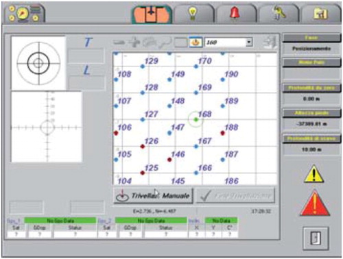
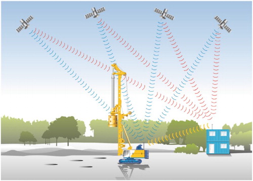
QC for shaft acceptance is performed via visual observation/inspection of the construction process, which is common practice in both Europe and US, as well as non-destructive testing (NDT) such as low-strain integrity testing, CSL, gamma/gamma logging (GGL) and thermal integrity profiling (TIP). In its simplest form, QA during shaft construction is provided through verification of positioning and the implementation of vertical survey tools. The as-built location of a drilled shaft/bored pile potentially affects its response to applied loads, hence pile placement requires a high level of accuracy between the installation location and the design location as well as the identification of any significant deviation during installation. The drilled shaft/bored pile is composed of two important data sets: (1) the top of the pile/shaft, and (2) the tip of the shaft/pile which is affected by the verticality of the drill rig and the stiffness of the drill string/Kelly bar. While GPS-based positioning has previously been used in other branches of the construction industry, GPS-based horizontal positioning systems directly attached to the drill rig are relatively new to the foundation industry. Examples of currently employed positioning systems are depicted in and . shows an Automatic Positioning System (integrated into Soilmec’s Drilling Mate System) and an Assistant Positioning System (B-APS, integrated into Bauer B-Tronic). Both systems use GPS/GLONASS to provide the horizontal positioning of the drill rig. The drill rig operator utilised the system to position the drill mast and ultimately the drilling tool into the pre-designated location. While European contractors appear to have adopted the automated positioning systems provided by the equipment manufacturers more frequently, there seems to be limited implementation in North America.
1 Screenshot Automatic Positioning System (Soilmec S.p.A. Citation2010)
2 Schematics and Bauer – Assistant Positioning System (Bauer Citation2015)
In addition to automated positioning systems, state-of-the-art drill rigs are equipped with inclinometers attached to the drill mast and monitored by the operator to ensure the verticality of the mast. The front-end person will also use a 4-ft level placed directly on the Kelly bar or casing at two locations at 90 degrees apart to verify the verticality of the mast. The approach to making measurements for the verticality of a drilled shaft/bored pile depends on whether the drilled shaft/bored pile is excavated using the dry method or using the slurry method ().
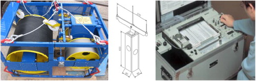
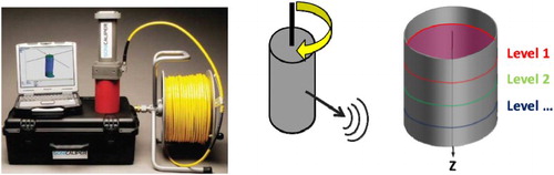
If the shaft/pile is excavated using the dry method, the bottom of the drilled shaft/bored pile can be sighted from the top. On the basis of the percentage bottom shaft visible to the inspector, the verticality of the shaft can be verified and either approved or rejected. If this method does not provide sufficient accuracy to validate the verticality, methodologies used for shafts with slurry should be used. Latest technological advances employed, when verifying the bottom verticality of bored piles/drilled shafts filled with water or slurry, are ultrasonic methods. In ultrasonic methods, the travel time of a sound wave travelling from shaft top to a sensor located at the shaft bottom is measured. Ultrasonic equipment currently employed includes the Koden, the Sonicaliper. Both devices provide indirect measurements and require interpretation and judgement by the testing agency. The Koden monitoring system consists of a weighted sensor that is lowered into the excavation ().
3 a Koden monitor with winch unit, b probe and c Koden recorder unit (Koden Citation2013)
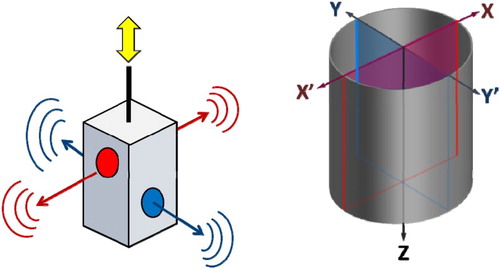
While the sensor is lowered or raised to/from the bottom of the shaft, ultrasonic signals are emanated in either two or four directions. The hole geometry is interpreted from measurements of the time it takes for the signals to travel back to the sensor as the signals are reflected off the excavation sides. The four vertical profiles generated using this approach are conceptually depicted in . These profiles are then plotted and provide a graphical representation of the verticality and diameter over entire length of the shaft/pile. In the case of larger deviations from plumb, more accurate results on verticality and actual diameter can be obtained by post-processing the data using circle fitting procedures. Beyond immediate analogue printouts, digital data are recorded for long-term retention or further analysis of the results.
4 Schematics of sensor action (left) and vertical profiles created by the Koden monitor (right)
The SoniCaliper, as shown in , is an ultrasonic echo device for interpreting the verticality and cross-sectional dimensions of the excavation. In addition, it can be used to verify the drilled shaft/bored pile volume. Beyond these functions, correlations to the cleanliness of the slurry have been developed by evaluating the interruption or loss of signal during testing of a particular zone.
5 SoniCaliper equipment (left; Loadtest Citation2012), schematics of sensor action (centre) and created horizontal profiles (right)
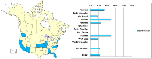
shows the areas within the United States where the usage of the SoniCaliper was reported. also presents a comparison of the usage with the US as well as between the US and Europe (see bottom of Figure). Both regions, i.e. US and EU, estimated similarly frequent implementation of this device namely about 25% (). For clarification, the reader is reminded that the incidence of respondents indicating either their use of or their observation of the use of these devices is about 25%. This does not mean that 25% of the drilled shafts/bored piles in the area are installed on projects using these devices. Most of the ‘measuring’ methods presented here are indirect.
6 Reported usage of SoniCaliper throughout North America (left) and ratio of responses stating the usage of the SoniCaliper and total responses per region
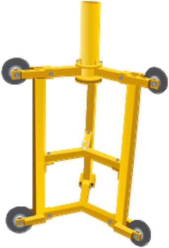
The Rope Inclinometer, as shown in , is a frequently used device in the European market. Its primary use applies to fully cased bored piles/drilled shafts, and relies on a measurement of the verticality of the rope on which the carriage is lowered into the drilled shaft/bored pile. This device measures the inclination of the rope in two dimensions in order to provide the inclination and orientation of the shaft/pile.
7 Rope inclinometer system: top unit (left) and carriage (right), both BAUER Spezialtiefbau (Citation2009)
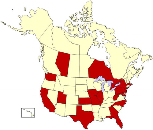
The verification of the shaft cleanliness and end-bearing capacity is common practice in the industry. Visual inspection is a widely accepted method for verifying excavation cleanliness and base conformity (). As is illustrated by the map, most states in the US and some of the Provinces of Canada use some type of visual verification during the drilling of a shaft/pile.
8 Reported application of visual shaft inspection throughout North America
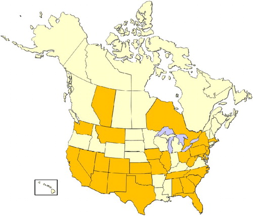
For dry shafts, visual inspections are the most common way of inspecting a bored pile/drilled shaft for cleanliness of the bottom. For non-end-bearing piles/shafts, on the West Coast of North America, visual inspection is typically performed from the ground surface using a mirror to direct sunlight into the bottom of the shaft to allow the inspector position at the shaft top to examine the cleanliness of the shaft. If a shaft is designed for end-bearing, a more stringent visual inspection may be required. On the East Coast of North America, where most bored piles/drilled shafts are designed for end-bearing, the bottom of the shaft is often directly observed requiring a downhole entry for the inspection, hand cleaning as required and even coring at the bottom of the pile/shaft to verify the bottom material.
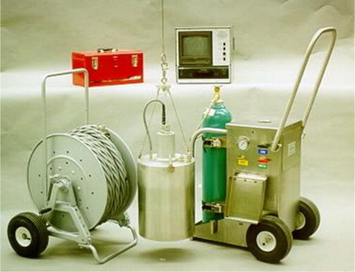
When it is not feasible to enter the excavation for inspection, or when the drilled shaft/bored pile is constructed under slurry displacement methods, visual inspections have to be replaced with other approaches. The conventional practice involves sounding the excavation bottom with a heavy weighted tape. In some cases, the SID or Miniature Drilled Shaft Inspection Device (Mini-SID, see ) or a downhole camera can be used to provide a video of the bottom conditions. The SID or mini-SID consists of a bell with a camera and a lighted system with a measuring probe which permits inspection of the bottom of the excavation and verification/measurement of the amount of loose sediment. The contract specifications typically provide criteria such as the maximum amount of sediment allowed over a particular area along with an average depth.
9 Miniature Drilled Shaft Inspection Device (GPE Citation2001)
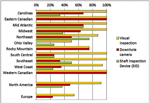
illustrates the downhole camera usage in North America according to survey results. A comparison of and suggests that the downhole camera usage is not as widely employed. compares the use of visual inspection, downhole camera and the SID (or Mini-SID). Visual Inspection is, by far, the most widely used method for ensuring shaft cleanliness. The SID is essentially unknown in Europe. Generally, we find that those types of inspections are much less popular in Europe than throughout North America. To reiterate, comparison is based on the survey respondents who have witnessed the use or the respective methodology and does not indicate that there is 100% use of any technique for all drilled shafts/bored piles.
10 Reported usage of downhole camera throughout North America.
11 Ratio between responses stating the usage of visual inspection, downhole camera and shaft inspection to total responses per region.
In order to evaluate the quality of the finished concrete pile, pre-concrete placement inspections (such as rebar and spacing inspections), as well as co-placement inspection (i.e. verification of concrete placement procedures, slumps tests, etc.), and post-placement inspections are performed. Typical methods utilised to assess the in situ concrete pile are destructive (coring) and NDT methods. Non-destructive methods are generally preferred and include GGL, which is also known as Gamma Density Logging (GDL), CSL, which in Europe is also known as Sonic Coring, and TIP. NDT requires the implementation of inspections tubes at pre-determined locations before shaft construction and rebar placement. For this, proper clearances must be guaranteed. The AASHTO recommends a minimum clearance of five inches between inspection tubes and reinforcing steel but provides spacing guidance based on the aggregate size. GGL and CSL both require inspection tubes to be installed into the reinforcing cages.
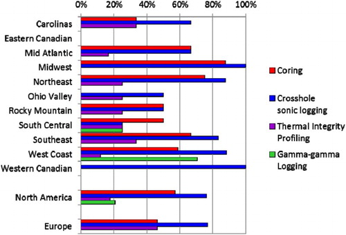
Guidance in North America for low-strain integrity testing is provided through ASTM D5882, while Europe follows recommendations from ASTM D5882 as well as local or national codes (such as NFP94-160-2, NFP-160-4, ICE 2007. In North America, CSL follows ASTM D6760 recommendations and is frequently performed on public and private work in most states and provinces of North America. In Europe, CSL is performed in France, Germany and in the UK according to local codes (NFP94-160-1) or the ASTM standard. GGL is commonly employed in California and Arizona (usually with CSL for confirmation in the event of anomalies). Little to no use was observed in other states. GGL/GDL is not typically performed in Europe, even though a French standard document exists – XP-160-5. presents a comparison of all test methods using the survey response. It is evident that CSL is the primary non-destructive test method performed in both North America and Europe. Note that these methods are rarely used for dry method construction and predominantly implemented in shaft construction involving slurry displacement procedures.
12 Ratio between responses stating the usage of coring, CSL, TIP and GGL to total responses per region
TIP represents a relatively recent method which can be conducted using the access/inspection tubes, or preferably without the installation of tube by placing thermal wire cables before concrete placement. TIP per ASTM D7949 is currently applied in Florida, Indiana, Michigan, Ohio and Washington. Some states in the Midwest of the US are exploring the usage of TIP in parallel with CSL. In Europe, TIP is widely used in London and slowly gaining acceptance and implementation in parts of Austria, France, Germany and Switzerland.
Static load testing to verify capacity
Conventional Tension, Compression and Lateral Load Testing in North America is guided by ASTM D1143 – Axial Compressive Load, ASTM D3689 – Axial Tension Load Testing, and ASTM D3966 – Lateral Load. In Europe, the Eurocode 7 defines the application of these tests and for each test a dedicated European Standard is currently under preparation as part of EN 22477:
Part 1: Pile load test by static axially loaded compression (in preparation)
Part 2: Pile load test by static axially loaded tension (in preparation)
Part 3: Pile load test by static transversally loaded tension (in preparation).
Until these documents are released, the tests are performed in accordance with either the ASTM standards or various local codes or standards.
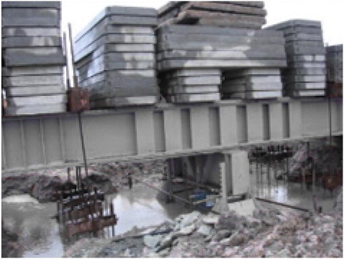
Static load tests using conventional ballast methods (i.e. Kentledge method) were common on bored piles for low to moderate design/test loads (typically, less than about 300 tons (2.7 MN)). However, as test loads increased, this type of testing became too cumbersome (i.e. construction of large reaction frames and tiedown anchors/reaction shafts) and dangerous (i.e. stacking weights higher and higher), and it became evident that this method had reached its practical limit. An alternative to ‘stacking weights’ on top of the test specimen is the usage of anchor piles, or the combination of anchor piles and weights, also referred to as compound method (anchor–kentledge) as shown in .
13 Compound (anchor–kentledge) load test. (Figure taken from www.piletest.eu)
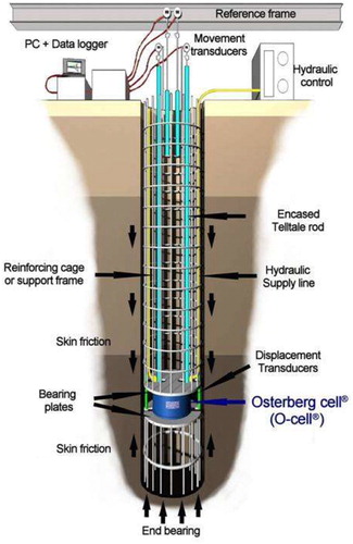
Static load tests utilising the bi-directional Load Cell (e.g. O-Cell, ) are widely used in North America; however, no guidance standard is currently published. The ASTM committee D18 is currently working on the development of a standard document. Bi-directional Load Cell testing is rather rare in Europe, and until a European Standard is issued most European countries will adopt the ASTM standard when published.
14 Schematics Osterberg load cell test (Loadtest Citation2016)
Dynamic and RLT to verify capacity
As an alternative to static load testing, the shaft capacity can also be verified through High Strain Dynamic Testing or force-pulse testing, also known as rapid load testing (RLT). The first method is regulated in the US by ASTM D4945 and in Europe by the same standard, albeit that work is continuing on a European Standard for this test (EN 22477 part 4). While this test is widely accepted in the US as a reliable alternative to static load testing, in Europe there is still the perception that high strain dynamic testing is a complimentary test to static load testing, and should be correlated to static load tests, especially in case of cast in-situ piles. At the same time this type of testing is a good method of increasing the population of piles to be tested and to give greater confidence in the design, and it works well on pile shafts with uniform section and material quality. At the same time the accuracy of test is much dependant on the skill and experience of both the tester and the analyst and there is also some controversy within the industry about the factors that affect the accuracy of the capacity predictions.
RLT is conducted in North America per ASTM D7383 and in Europe per EN 22477 part 10.
When the capacity is not confirmed by a static load test, some codes require higher factors of safety (or capacity reduction factors), albeit that this change can be minimised by increasing the number of tests performed.
QA/QC influence on test results
QA/QC requirements can affect the design and construction processes when the proposed QC methods require installation of materials within the foundation during construction – i.e. CSL or GGL access tubes, bi-directional load cells, strain gages, displacement telltales etc. In those cases, additional QA measures are necessary to ensure that the equipment and materials are correctly and accurately installed and documented. For example, the DFI Drilled Shaft Inspector’s Manual advocates measuring and documenting the locations of all splices or joints and the fixing points of CSL access tubes before reinforcing cage installation, because they are likely to show up as ‘anomalies’ in CSL or GDL data. Similarly, CALTRANS specifications allow the use of adobe or cement blocks as reinforcing cage spacers/centralisers. Those blocks may appear as density variations in GDL data. Where plastic spacers are used, they may cause some localised pockets of segregation which will also show up as density variations, so specifications also require that the spacer or block locations be accurately documented for correlation with test results. Where bi-directional load cells are installed at locations other than the base of the shaft, some US specifications require that CSL testing be performed before the load test, to verify that no deleterious material has been trapped under the cell that could adversely affect the load test result.
QA/QC specifications
QA/QC requirements and the test results generated through the requirements have been the catalysts to the development of many innovations and improved practices used by contractors today. However, issues arise when owners issue specifications for construction and QM procedures using a cut-and-paste approach, or specifying outdated methods or technologies. There is no one-size-fits-all solution for specifications. Contractors and testing agencies must be prepared to educate the owners if they issue a poorly worded, outdated or inappropriate specification.
Typical practice with respect to the BP/DS QA/QC specifications in North America can be distinguished as follows:
Government and state agencies (FHWA, DOTs, etc.): QM specifications for many Federal and State foundation projects are often buried in the contract specifications (and sometimes even in the Special Provisions attached to the specifications), and are then part of the foundation contractor’s responsibilities.
Municipalities: Larger municipalities like the cities of Chicago and New York have developed their own codes and specifications for deep foundation construction and QA/QC. Smaller municipalities tend to follow either the local State DOT policies, or FHWA guidelines.
Private owners: Unless the local municipal code prevails, private owners tend to rely on their engineer of record for QA/QC recommendations.
In Europe, QA/QC practices were difficult to assess. Among practices recommended by Government and State Agencies (DOTs etc.), QA/QC requirements and recommendations varied widely. However, with further development and adaption of the Eurocodes, the practices are anticipated to become more uniform. No specific information was obtained on municipal regulations; however, for private owners, similar observations as in the US were made, unless prevailed by municipal standards or state regulations. It was noticed that private owners tend to rely on their engineer for the QA/QC decision making.
Summary
Evidently, there exist many similarities between QA/QC practices for BP/DS construction in Europe and North America and technologies are readily available on both continents. Nevertheless, their application varies widely for a variety of reasons. For critical foundations with no redundancy, such as single piles supporting individual bridge piers, Crosshole Sonic Logging (CSL or Sonic Coring) is used both in Europe and in North America, but TIP is winning converts on both sides of the Atlantic. For groups of piles with some redundancy, as often found in bridge abutments or tank and silo bases, low-strain integrity tests are the norm, often with a selective test programme, such as testing the first 10 or 20 shafts constructed, then selecting a percentage of the remainder at random, or when something unusual is noted by the contactor or inspector during the construction process.
In short, there is as much variation in preferred QA/QC practices between North American states and provinces as there is between European countries. However, one common and concerning observation made on both sides of the Atlantic was the significant number of testing firms with no or very limited understanding of the drilled shaft construction process, which therefore failed to ask for critical and readily available construction records before interpreting their test data, or provide any opinion as to the nature and cause of any anomalies. Another concern is related to the ‘cut-and-paste' practice of specifications or special provisions compiled by engineers who had little or no knowledge of the test methods, which resulted in specification of tests that were either inappropriate for the site conditions or for the information required. In either case, the test results are likely to be inconclusive at best, and misleading at worst. Therefore, great opportunity exists for continuing professional education and further development of specification and standards to improve current QA/QC practice on both continents.
Notes
1 CEN members are Austria, Belgium, Cyprus, Czech Republic, Denmark, Estonia, Finland, France, Germany, Greece, Hungary, Iceland, Ireland, Italy, Latvia, Lithuania, Luxembourg, Malta, Netherlands, Norway, Poland, Portugal, Slovakia, Slovenia, Spain, Sweden, Switzerland and United Kingdom.
References
- ASTM D7383. Standard test methods for axial compressive force pulse (rapid) testing of deep foundations. West Conshohocken, PA: American Society for Testing and Materials.
- BAUER Maschinen GmbH. 2015. B-APS BAUER – assistant positioning system. Promotional information PI 117 03/2015. https://www.bauer.de/export/shared/documents/pdf/bma/datenblatter/B-APS_DE-EN_PI117.pdf
- BAUER Spezialtiefbau GmbH. 2009. Rope Inclinometer “Seilneig” (Type IV) – Verticality measurements in cased boreholes. http://www.bst-messtechnik.de/export/sites/www.bst-messtechnik.de/pdf/pdf_mit_schutz/rope-inclinometer_en.pdf
- DGGT German Geotechnical Society. 2014. Recommendations on piling (EA-pfähle). Ernst & Sohn, Berlin, Germany.
- GPE, inc. 2001. Miniature Drilled Shaft Inspection Device (Mini-SID). http://www.gpe.org/products/miniSID.htm
- Koden Electronics Co., Ltd. 2013. Koden Ultrasonic Drilling Monitor DM-602/604.http://www.koden-electronics.co.jp/eng/industrial/pdf/industrial/dm602604-e130920.pdf
- Loadtest. 2012. SoniCaliper. http://www.loadtest.com/services/SoniCaliper.pdf
- Loadtest. 2016. O-cell Load Testing. http://www.loadtest.com/services/ocell.htm
- Soilmec S.p.A. 2010. APS Automatic Positioning System. http://www.soilmec.com/downloads/2329/95/1362__aps.pdf