Abstract
An appropriate logistics network is an important element of the infrastructure of any product recovery company. Small and medium enterprises (SMEs) constitute a major fraction of the product recovery industry with a different business objective and scale of operation from those of original equipment manufacturers. This paper addresses the network design issues for SMEs involved in product recovery activities. A mathematical formulation is presented in an SME context and a subsequent simulation model is developed. A genetic algorithm approach is presented for optimising the network for a single product scenario.
1. Introduction
Recovery of used products and materials has attracted researchers' attention for many years. However recently, the enforcement of environment friendly policies, by different governments, and customer enthusiasm for greener production, has encouraged companies to start product take‐back activities. The products are collected at the end of their life with the aim of recovery or safe disposal.
Product recovery is the transformation of used and discarded products into a useful condition through reuse, remanufacture and recycling. Implementation of product recovery requires setting up an appropriate logistics infrastructure for the arising flows of used and recovered products. Physical locations, facilities and transportation links need to be chosen to convey used products from their former users to a producer and then to future markets. Reverse logistics encompasses the logistics activities all the way from used products, no longer required by the user to recovered products that are again usable in a market. The study of reverse logistics can be broadly divided into three areas:
-
distribution planning, which involves the physical transportation of used products from the end user back to the producer;
-
inventory management, which is the process of managing the timing and the quantities of goods to be ordered and stocked, so that demands can be met satisfactorily and economically;
-
production planning, which despite not being a logistics activity, greatly influences the other two (Salema et al. Citation2007).
One of the earliest publications addressing distribution issues was that by Gottinger (Citation1986). Thereafter, several models have been proposed which focus on aspects such as product recycling and planning/distribution (Caruso et al. Citation1993, Giannikos Citation1998, Fleischmann et al. Citation2001). A more general classification of the research areas related to reverse logistics is provided by Dekker et al. (Citation2004) and presented by Rubio et al. (Citation2008), in which the following areas were identified:
Management of the recovery and distribution of end‐of‐life products. | |||||
Production planning and inventory management. | |||||
Supply chain management issues in reverse logistics. | |||||
The main activities in reverse logistics are the collection of the products to be recovered and the redistribution of the reprocessed goods. The reverse logistics problem looks quite similar to the normal forward distribution problem; however, there are some differences too. Reverse flow of goods is convergent in nature, so the products need to be collected from many points. Therefore, cooperation of the senders becomes important as product packaging is generally problematic. Products flowing in the network tend to have low value. On the other hand, time is not as important an issue as it is in forward distribution. Taking these issues into consideration, reverse logistics require the construction of new networks. The major issues concerning the design of a recovery network are: the determination of the number of tiers in the network; the number and location of collection/drop‐off and intermediate depots; and the interaction of the reverse chain with the forward chain.
Recently, a number of case studies have been reported in the literature that address the design of logistic networks in the product recovery context. Kroon and Vrijens (Citation1995) address the design of a logistics system for reusable transportation packaging. They discuss the role of the different actors in the system, economy, cost allocation, amount of containers and locations of the depots. Castillo and Cochran (Citation1996) discuss the distribution and collection of reusable bottles for a soft drink company while Duhaime et al. (Citation2001) address the same issues for reusable containers for Canada Post. Alshamrani et al. (Citation2007) develop a heuristic procedure for route design and pickup strategy for a network inspired by blood distribution by the American Red Cross. Krikke et al. (Citation1998) address the remanufacture of photocopiers and, as remanufacturing is a labour intensive process, they compare two remanufacturing options for the company; one coinciding with the existing manufacturing network and the other in another country where labour is cheap. Barros et al. (Citation1998) report a case study discussing the design of a logistics network for recycling sand coming from construction sites as waste. Recycling of carpet waste is addressed by Louwers et al. (Citation1999) and Realff et al. (Citation2000) and a mixed integer linear programming (MILP) model for the recycling of industrial by‐products in the German steel industry has been developed by Spengler et al. (Citation1997). Krikke et al. (Citation2003) provided an overview of key papers on reverse supply chain modelling and developed a quantitative model to support decision making concerning the design structures of both the product and the logistic network.
The above examples highlight the fact that most research in the area of reverse logistics network design has been case‐specific. The most generic model for the design of a reverse logistic network is the one proposed by Fleischmann et al. (Citation2001). This model considers the impact of product recovery inclusion on the forward network and the model was optimised taking into account both the flows. An MILP formulation is proposed extending the traditional warehouse location problem and integrating the forward chain with the reverse chain. This work was subsequently extended by Salema et al. (Citation2007) who accommodated capacity constraints, a multi‐product scenario and uncertainty.
2. The recovery network
In the present literature, much of the published work addresses problems involving big market players like Hewlett Packard, Canon, Dell and other original equipment manufacturers (OEMs) in the electronics industry. Similarly, the published research work dealing with other types of industries focuses on the original manufacturers' point of view. However, as previously highlighted, the recovery industry largely consists of smaller, independent recovery companies. These companies are not OEMs, so for them merging their procurement process with the distribution is not of great importance as their markets are quite different from those of OEMs and their markets for recovered products may well be different to the sources of products for remanufacture. As these companies are small and medium enterprises (SMEs) and recovery is their main job, the design of an efficient recovery network is extremely important as the damage caused by network inefficiency cannot be compensated from other means. This paper presents a mathematical model for the design of a network for a third party recovery firm. The formulation is based on Fleischmann et al. (Citation2001), however, the context is quite different as Fleischmann et al. (Citation2001) present a generic model for companies wanting to integrate reverse logistics into their existing supply chain. In contrast the context of the initial network design formulation presented in the next section addresses network design issues for SMEs dealing with remanufacturing of returned items. The need for developing the network optimisation model was realised when the authors visited one of the UK's leading companies in the independent recovery industry. This visit developed the authors' understanding of the problems that such companies face. These include storage space for their facilities and the uncertainty regarding the returned items. Hence the model developed in this research includes capacity constraints and a simulation approach was employed to map the uncertainty. For the sake of simplicity, a single product scenario was first formulated and the optimisation tool was developed with it. Then it was converted to a multiple product model. The model was optimised using a genetic algorithm in conjunction with a simulation approach. The use of simulation helped the incorporation of the uncertainty associated with product returns. The computational setup is discussed in later sections of this paper and the proposed mathematical model is described below.
2.1 Mathematical model for a single product recovery network
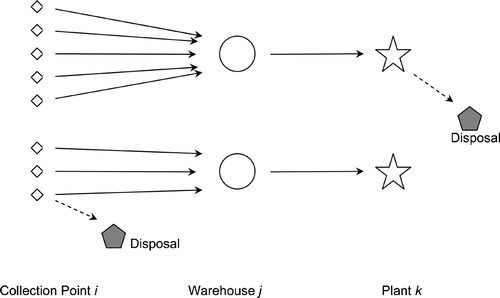
As mentioned earlier, the motivation for the model comes from the authors' experience with industry. Three facility levels are considered, i.e. collection points which are responsible for collecting the used products and initial inspection if they are equipped with adequate facility, warehouses where returned products are stored and plants which finally reprocess them (Figure ).
While establishing a distribution network, it should be taken into account that facilities have limitations on the number of products they can store or process. These limitations are due to various factors like availability of space, number of workers and workstations, etc. The network model addresses these limitations by incorporating capacity constraints for each facility.
The proposed recovery network model involves the following index sets, variables and parameters:
Index sets
i ∈ I; where I = {1, …, Nc } fixed locations for collection points
j ∈ J; where J = {1, …, Nw } potential locations for warehouses
k ∈ K; where K = {1, …, Np } potential locations for plants
Costs
fixed cost for enabling collection point i for inspection
fixed cost of opening warehouse j
fixed cost of opening plant k for disassembly and reprocessing
T collective cost of storage at collection points, warehouses and plants
P unit penalty cost for not processing returned product
tcw unit transportation cost from collection point i to warehouse j
twp unit transportation cost from collection point i to disposal site l
cp unit cost of reprocessing
cd unit cost of disposal
Cijk cost of reprocessing returned product from collection point i coming through warehouse j at plant k
Dijk cost of disposing of the returned product coming from collection point i through warehouse j and plant k
Sijk cost saving by disposing the discarded returned product at inspection enabled collection point i (and not traverse it through warehouse j and plant k)
If dpq be the distance between points p and q in the distance matrix; we calculate the above costs as follows:
Variables
yijk fraction of returned products served by collection point i, warehouse j and plant k
zi fraction of the returned product at collection point i which can not be reused (chosen with a random distribution)
Parameters
Ri return from collection point i; i ∈ I
maximum capacity of collection points i; i ∈ I
maximum capacity of warehouse j; j ∈ J
maximum capacity of plant k; k ∈ K
Using the above notation, the mathematical formulation to minimise the sum of the fixed, variable and penalty costs is as follows:
The above formulation minimises the fixed cost for the setup of facilities and costs involved in the recovery/disposal processes. The three terms in equation Equation(5) represent the cost of installing inspection facilities at collection/drop‐off points and setup costs for warehouses and reprocessing plants. The first term in equation Equation(6)
maps transportation costs and reprocessing/disposing costs for the reprocessing/disposing of product, while the second term in this equation involves cost savings for the product if the collection point it is coming from has inspection facilities installed. The returned products which are not processed due to the capacity constraints pose a loss and are mapped by equation Equation(7)
. Constraint (8) ensures that all the returns are taken into consideration. Equations (Equation9
–Equation
Equation11
) make sure that the capacities of the facilities are not exceeded.
The formulation is generic in nature and can reflect recovery scenarios for various kinds of products. The disposal of unusable products from collection points as well as from plants may involve sending them to a third party recycler/disposer or to the remanufacturer's own facility and the associated transportation cost. This model just requires the flow of such items to leave the network after sorting.
3. Optimisation of the model
One of the major characteristics of problems concerning reverse logistics activities is the uncertainty associated with the return of products, including quantity, quality and timing. The stochastic nature of these problems means that most of the analytical models become either too simplistic or exceptionally complex. Discrete event simulation is regarded as the most suitable analysis tool for such situations and is largely used to evaluate ‘what‐if’ scenarios (Schroer and Tseng Citation1988, Smith et al. Citation1994, Fishman Citation2001). In this research, a simulation based approach is used for the optimisation of the model.
3.1 Solution methodology
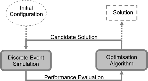
A general simulation‐based optimisation method consists of two essential components: an optimisation module that guides the search direction and a simulation module for evaluation of the performance of candidate solutions. The decision variables create the environment in which the simulation is run while the output of the simulation runs is used by the optimiser to progress the search for an optimal solution (Figure ).
In the existing literature, a number of simulation‐based optimisation methods have been reported and include gradient based search, stochastic approximation, sample path optimisation, response surface, heuristic search methods and evolutionary algorithms (Andradóttir 1998, Azadivar 1999). There are several metaheuristic optimisation algorithms present in the literature like tabu search (TS), simulated annealing (SA), ant colony optimisation (ACO) and genetic algorithm (GA). The performance of TS and SA deteriorate significantly as the problem size and solution space increases (Woodruff Citation1994). The ACO approach is best suited for the travelling salesman problem and needs to be manipulated to address other types of optimisation problems (Dorigo et al. Citation1996, Dorigo and Gambardella Citation1997). According to an empirical comparison of search algorithms by Lacksonen (Citation2001), GA appears to be the most robust for solving large problems although it requires a large number of replications.
In the past, GA has been successfully applied to classical combinatorial problems such as capacitated plant location (Gen et al. Citation1999), fixed charge location (Jaramillo et al. Citation2002), minimum spanning tree (Zhou and Gen Citation1999), network design (Palmer and Kershenbaum Citation1995), and warehouse allocation (Zhou et al. Citation2003). Genetic algorithm has been applied to the network design problem for reverse logistics as well (Min et al. Citation2006, Ko and Evans Citation2007, Lieckens and Vandaele Citation2007). Because of the proven effectiveness of GA for various combinatorial problems, it has been adopted in this research to perform a stochastic search for solutions. The details of the algorithm are discussed in subsequent subsections.
3.1.1 Simulation model
A simulation‐based optimisation method has been developed for the optimisation of a network design problem, keeping the constraints within the model logic. The simulation model was created in Arena 10.0 (Kelton et al. Citation2007), which was selected over other available simulation software because of its seamless integration with other software supporting Microsoft technologies. Arena exploits two Windows technologies that are designed to enhance the integration of desktop applications. The first, ActiveX Automation allows applications to control each other and themselves via a programming interface. The second technology exploited by Arena for application integration addresses the programming interface issue. In this research, the code for the optimisation algorithm was written in Visual Basic (Deitel et al. Citation1999) and uses the Arena model for the evaluation of candidate solutions.
In the simulation model, the entities representing returned products in the model are generated on a daily basis and the number of products is decided by normal distribution with a mean proportional to the population of the customer zone. Each entity carries attributes of its origin customer zone, warehouse and plant locations and reusability. The decision about whether a facility is open or not is coded in the candidate solution sent over by the GA code while Arena VBA blocks decide which alternative facilities are available for the entity to use.
3.1.2 Genetic algorithm representation and operations
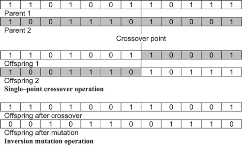
One of the most important aspects of genetic optimisation is the chromosome encoding for representation of a typical solution. The encoding depends largely on the nature of the problem. In this case, the chromosome is an array of binary variables as shown in Figure . The individual binary arrays for facilities at all the tiers are concatenated to form chromosomes for binary representation of the solution. As the chromosome consists of variables of uniform nature, the genetic operations are performed on the whole of the chromosome at once. Each binary variable in the chromosome represents the installation of the associated facility.
Crossover and mutation are two basic genetic operations for the optimisation search. The crossover method applied in this work is Single Point Crossover illustrated in Figure . In this method, a position is selected randomly. The binary string from the beginning of the chromosome to the crossover point is taken from one parent and the rest is copied from the other parent. As shown in Figure , this operation can produce two offspring chromosomes using one crossover point. In this work, the parents are selected by roulette wheel selection and both of the produced offspring chromosomes are included in the new population. To maintain the diversity of the population, and save the search from getting trapped in local optima, GA uses another operation called mutation. Based on the mutation probability, the produced offspring is subjected to mutation operation, using a Bit Inversion Method (although several other methods could be used instead). In this method, the binary bits of the chromosome are inverted (a NOT binary operation is applied) as shown in Figure .
3.1.3 Determination of probability values
The best values of these probabilities for a particular problem are decided with a small set of experiments. First a couple of arbitrary sets of values are chosen. Then a sample problem is chosen and its time horizon is greatly reduced and accordingly the costs are adjusted. For example if a 1‐year problem is reduced to 1‐day, the associated annual costs are also reduced accordingly. Now the average iteration time comes down to a few seconds from the original 2 to 4 minutes. With the help of these reduced examples, the algorithm was run for different sets of the probabilities and the appropriate values of the probabilities were determined. These sets of probabilities vary for different types of problems and hence need to be determined for each individual problem.
3.2 Test problems
3.2.1 Problem description
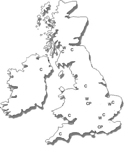
A hypothetical example of a single product recovery enterprise has been used to analyse the model. The structure and functionality of the hypothetical company is based on experience gained from the product recovery industry and the design of the reverse logistic network for an SME, dealing with printer cartridge remanufacture, is considered. It is assumed that the SME procures used cartridges from certain customer zones through its collection points spread across the UK (Figure ). The collection points procure used cartridges from independent retailers and high volume users irrespective of their condition (reusable/unusable). The returns coming from the customer zones are assumed to be proportional to their population. The collection points may or may not have facilities to sieve out unusable products. If the products are found to be unusable in an inspection enabled collection point they are sent directly to the disposal site. This saves costs of storage and transportation of the unusable product at different tiers of the network. The transportation cost involved in the transit between different tiers of the network varies and generally it is higher in the case of transit from collection points to the warehouse than in the case of transit from the warehouse to the plant. From the collection points, the cartridges are sent to warehouses for storage. Plants have facilities to inspect and reprocess the products.
The design problem poses several questions for the decision maker in the SME. For example, depending on the location of collection points, the nature of the returned product will vary. Some collection points with large volumes of returns might actually have benefits if they are enabled with inspection facilities. The location of the warehouses and plants is another strategic issue to save transportation and handling cost. The complexity of the problem multiplies as the numbers of tiers and products increase.
3.2.2 Generation of example problems
Based on the above description and the understanding developed from a survey of the available literature, the ranges of costs and parameter values were decided as listed in Table . Ten data files were created, with values uniformly distributed in the ranges as shown in Table , for the optimisation tool to create random example problems. The example problems were created in accordance with the problems presented in Fleischmann et al. (Citation2001).
Table 1. Parameters and costs (in GBP) for the SME example.
3.3 Simulation based optimisation tool
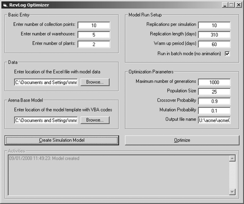
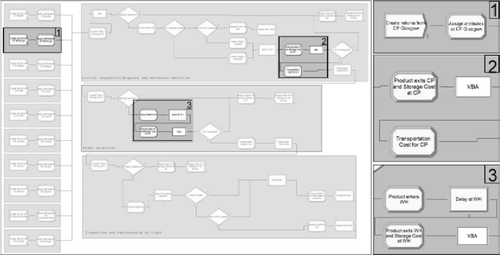
A tool was developed in Visual Basic to handle the GA based optimisation task for the network configuration, and a screenshot of this optimisation tool is shown in Figure . This tool works in conjunction with a simulation model template created in Arena. This template contains the modules and VB codes common to all types of problems under consideration. The optimisation tool gets the basic data from the user through its graphic user interface and loads the detailed information specific to the current network problem from this user specified data. The tool then invokes Arena to load the model template to modify the existing modules and create new ones. A screenshot of an Arena model created by this tool is shown in Figure . The model shown has 10 collection points generating a number of entities (representing returned products) on every working day based on a uniform distribution. Attributes representing origin, destination warehouse and reprocessing plant and inspection tags are created for each entity. The entity travels through the various VBA logic blocks and decision modules, which determine the destination warehouses and plants of the entity and assign it to the respective attributes. These decisions are based on the model constraints and input in the form of candidate chromosomes. Associated costs are calculated as the entity travels through process blocks before being disposed (representing products being sent to market or recycled/disposed due to infeasibility of remanufacture). Once the model is created, the data related to the model run and parameters of the optimisation are entered by the user or retrieved from file to start the optimisation. The optimisation results are stored on a spreadsheet.
3.4 Performance of the optimisation approach
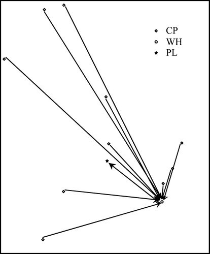
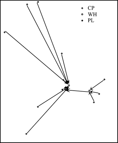
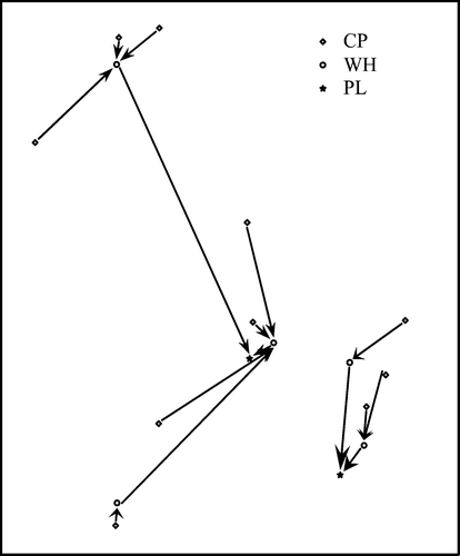
To test the genetic algorithm based optimisation approach, a small example of 10 candidate collection points (CP), five warehouses (WH) and two plants (PL) was considered, as shown in Figure . The generated model was optimised with the developed tool and gave reasonably good solutions at around the 300th generation. Figure shows the plot of best solutions obtained in generations for the first test set. The continuous plot in the figure shows convergence of the solution. Figures – show different configurations of the network as obtained by the iterative optimisation process and associated costs. Note that the cost associated with the network in Figure is not much higher than that in Figure , despite the longer traverse paths. This is due to the fact that the latter involved a fixed cost for setup of additional facilities.
Figure 8 Costs of best solution in the populations and the convergance of solution over increasing generations.
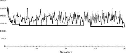
Figure 9 Initial configuration with all collection points(CP) inspection enabled, all warehouses (WH) working, all plants (PL) working; cost: £233,187.
4. Performance of the model
After generating various simulation models specific to the problem the optimisation was started. The fixed costs associated with the setup of facilities are annual costs hence the simulation horizon was set to one year. The warm‐up period, required for the simulation model to reach the steady state was set to one month. The duration of warm‐up period was decided based on the observations of pilot runs of the simulation. For each candidate solution, 10 replications of simulation were run to smooth out residual randomness. A large GA population will result in higher computational time and a lower one may lead to premature convergence of the solution. Hence there is always a trade‐off between the computational time and solution quality while deciding the GA parameters. The GA population for this problem size is set to 25 after observing a few test iterations while generating the initial population, one solution is predefined with all the facilities setup and the rest of the solutions in the population are randomly generated. At each generation, solutions are selected for crossover or mutation operations based on their respective probabilities. The optimisation tool was run on a Pentium 4HT Dual Processor PC running Windows XP at a clock speed of 3.06 GHz on 2 GB of RAM and took around 1 to 2 minutes per generation of GA.
4.1 Simulation model
The simulation model built for the optimisation is generic in nature and was modified according to the data provided by the optimisation tool and hence the model run for each problem is unique. The simulation model built for the optimisation is quite flexible in nature and the decisions with multiple influencing parameters/variables such as determination of destination facilities are taken by the VBA blocks built within it. The logic of these blocks can be slightly modified to give a competitive edge to certain facilities according to the problem scenario. Such tweaks in the logic are useful in those cases where facilities at geographically dispersed locations have different overall cost and time for processing products. Once the optimisation is finished, the models can be simulated without the help of the optimisation tool with the optimum or other set of configuration for further investigations.
In order to verify the correctness of the model, the values calculated by its logic were compared with manual calculations. It can be understood that performing the manual calculations of an entire simulation run will be impossible in terms of time taken. Therefore, a random sampling approach was taken. While running the model with a specific network configuration, the simulation was stopped at a certain date and all the parameters were calculated. Then based calculations were done for one day of operations and compared with the values obtained from the model simulation stopped at next day. These random verifications are carried out throughout the development of the simulation model so that its accuracy was checked and assured.
4.2 Reverse logistics network
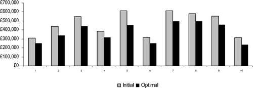
The optimisation was run on 10 examples generated using the values in Table . Figure shows costs associated with the initial and optimal configurations for the various example problems. It is observed that most of the configurations came out with only a few collection points enabled with inspection facilities. This is due to the fact that printer cartridges are one of the most ‘remanufacturable’ products, so the probability of being reusable is high (hence the parameter settings in the model). Cartridges have a very short life span and are generally handled with care. The short life span helps in two ways: the cartridges do not get much time to be mishandled and they do not become obsolete by the time they are returned. Hence they have a high probability of being in a reusable condition when they reach the remanufacturer. However, for a more complex product, the case is different. For example, a mobile device (phone or laptop) becomes obsolete within half of its life span! In such cases, having intermediate inspection sites would be helpful for channelling the product to disposal or to another type of reuse/recycle site. The above observation is also backed by Table , which shows the variation in number of inspection enabled collection points obtained from simulation runs with different values of reusability of the returned product.
Table 2. Reusability versus inspection enabled facilities.
5. Multiple product scenario
The formulation presented above addresses the network issue for an SME dealing with a single product. However, an SME in the independent product recovery business essentially deals with multiple products. For inclusion of multiple products, an index set of products is introduced:
l ∈ L; where L = {1, …, Nr } set of products
The notations for costs, variables and parameters will change to:
Costs
fixed cost for enabling collection point i for inspection
fixed cost of opening warehouse j
Pl unit penalty cost for not processing returned product l
Tl collective cost of storage for product l at collection points, warehouses and plants
unit cost of transporting product l from collection point to warehouse
unit cost of transporting product l from warehouse to plant
unit cost of reprocessing product l
unit cost of disposing product l
Cijkl cost of reprocessing returned product l from collection point i coming through warehouse j at plant k
Dijkl cost of disposing of the returned product l coming from collection point i through warehouse j and plant k
Sijkl cost saving by disposing the discarded returned product l at inspection enabled collection point i (and not traverse it through warehouse j and plant k)
Variables
yijkl fraction of returned product l served by collection point i, warehouse j and plant k
zil fraction of returned product l at collection point i which can not be reused (chosen with a random distribution)
Parameters
Ril total return of product l from collection point i; i ∈ I
Using the above notations, the mathematical formulation for the fixed, variable and penalty costs is as follows:
The constraints need to include the consideration of multiple products as well. So the modified constraints are:
The above formulation brings the model closer to a real‐world scenario by including multiple products. The same simulation based optimisation approach was used for the evaluation of the model, i.e. the optimisation in multiple product scenario was the same as that in the single product scenario. However, the simulation model needed alteration as the modules responsible for entering entities representing products required modification to produce multiple products and assign attributes to the model. The logic of the model also required modification to handle multiple products.
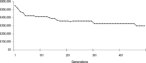
For initial experimentation on the multiple product scenarios, the problem described earlier was extended to two products. Going from one product to two may seem to be a small improvement, however it serves the purpose of allowing the possibility of inclusion of more than one product in the logistic network. The parameters and costs associated with the products are listed in Table . The fixed costs remain the same as in Table . The computational time increases to 2 to 3 minutes for a generation. With crossover and mutation probabilities of 0.85 and 0.1 respectively, the solution converges at approximately the 457th generation. Figure shows the costs of ‘best solution so far’ at every 10th generation of the optimisation iterations.
Table 3. Parameters and associated costs (in GBP) in the multiple product scenario.
5.1 Inclusion of multiple product in the network
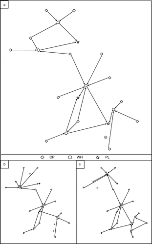
A company involved in the recovery business essentially deals with multiple products. The presence of multiple products makes the network optimisation problem more complex and has considerable impact on the output. Figure shows the optimal configurations for a network optimisation problem with 13 collection points, six warehouses and three plants. Figure is the optimal configuration with two products, in which all the collection points are inspection enabled and only one warehouse is not installed. The facility which is not installed can be identified as the one which is not connected by any arrow. However, when the same problem was run with either of the products, the optimal configuration was different due to the variability of availability and quality of products at different locations (Figure ).
6. Concluding remarks
To successfully implement the product recovery activities, an appropriate logistics network needs to be established for the flow of returned products. Logistic network planning involves decisions about the location of facilities as well as capacity planning for the concerned facility. For an independent recovery SME, decisions regarding storage are also vital as the uncertainty of quality and quantity of recovered products is high because of the wide range of products coming to the facility. This paper presents a mathematical formulation that addressed the network design issues for SMEs involved in independent product recovery activities. The formulation examined the inspection, separation and remanufacturing stages. Based on the formulation, a simulation model was created. The network configuration was optimised using a GA with fitness functions calculation conducted by the simulation model. The simulation model approach enables company managers to examine and compare the possibilities offered by various possible configurations through what‐if types of experiments. The optimum configurations obtained from the optimisation are then utilised to perform further investigations.
The initial formulation presented in this paper addressed the network issues for a SME dealing with a single product. However, the SMEs in the independent recovery business essentially deal with multiple products. Therefore, a multiple product formulation was also presented in the paper. The example shown with the multiple product formulation takes two products at a time, which at first glance does not look a big step ahead of single product scenario. However, the major difference in formulation and modelling for both the scenarios lies in the fact that even for two products, all the calculations are done with the help of iterations, which makes it mathematically possible to introduce any number of products.
This approach could be applied by the industry in an iterative way. The simulation approach utilised in calculating the fitness function for optimisation, makes use of predefined sets of values and parameters. These values and parameters are decided and/or calculated from previously available data either by simple averaging or by complex functions depending on the requirements. A decision on the configuration of the network is reached and the operations start to take place. Subsequently, management could come back to their model and check the optimality of the network. As the approach enables (and indeed benefits from) the use of ‘what‐if’ type of experiments, management will be able to evaluate the various scenarios in the altered environment.
References
- Alshamrani , A. , Mathur , K. and Ballou , R. H. 2007 . Reverse logistics: simultaneous design of delivery routes and returns strategies. . Computers & Operations Research , 34 (2) : 595 – 619 .
- Andradóttir , S. A review of simulation optimization techniques. Proceedings of the 1998 winter simulation conference , Edited by: Medeiros , D. J . pp. 151 – 158 . Piscataway, NJ : IEEE . 13–16 December 1998, Washington DC
- Azadivar , F. Simulation optimization methodologies. Proceedings of the 1999 winter simulation conference , Edited by: Farrington , P. A . pp. 93 – 100 . New York, NY : ACM . 5–8 December 1999, Phoenix, AZ
- Barros , A. I. , Dekker , R. and Scholten , V. 1998 . A two‐level network for recycling sand: a case study. . European Journal of Operational Research , 110 (2) : 199 – 214 .
- Caruso , C. , Colorni , A. and Paruccini , M. 1993 . Regional urban solid waste management system: a modelling approach. . European Journal of Operational Research , 70 (1) : 16 – 30 .
- Castillo , E. D. and Cochran , J. K. 1996 . Optimal short horizon distribution operations in reusable container systems. . Journal of the Operational Research Society , 47 : 48 – 60 .
- Deitel , H. M. , Deitel , P. J. and Nieto , T. R. 1999 . “ Visual Basic 6: how to program. ” . New Jersey : Prentice Hall .
- Dekker , R. 2004 . “ Reverse logistics: quantitative models for closed‐loop supply chains. ” . Berlin : Springer . 1st ed
- Dorigo , M. and Gambardella , L. M. 1997 . Ant colonies for the travelling salesman problem. . BioSystems , 43 : 73 – 81 .
- Dorigo , M. , Maniezzo , V. and Colorni , A. 1996 . The ant systems: optimization by a colony of cooperative agents. . IEEE Transactions on Man, Machine and Cybernetics: Part B , 26 : 1 – 13 .
- Duhaime , R. , Riopel , D. and Langevin , A. 2001 . Value analysis and optimization of reusable containers at Canada post. . Interfaces , 31 (3) : 3 – 15 .
- Fishman , G. S. 2001 . “ Discrete‐event simulation: modeling, programming, and analysis. ” . New York, NY : Springer . 1st ed
- Fleischmann , M. 2001 . The impact of product recovery on logistics network design. . Production and Operations Management , 10 (2) : 156 – 173 .
- Gen , M. , Choi , J. and Tsujimura , Y. Genetic algorithm for the capacitated plant location problem with single source constraints. Proceedings of seventh European congress on intelligent techniques and soft computing, Session CD‐7 , 13–16 September 1999, Aachen
- Giannikos , I. 1998 . A multiobjective programming model for locating treatment sites and routing hazardous wastes. . European Journal of Operational Research , 104 (2) : 333 – 342 .
- Gottinger , H. W. 1986 . A computational model for solid waste management with application. . Applied Mathematical Modelling , 10 (5) : 330 – 338 .
- Jaramillo , J. H. , Bhadury , J. and Batta , R. 2002 . On the use of genetic algorithms to solve location problems. . Computers & Operations Research , 29 (6) : 761 – 779 .
- Kelton , W. D. , Sadowski , R. P. and Sadowski , D. A. 2007 . “ Simulation with Arena. ” . New York, NY : McGraw‐Hill . 4th ed
- Ko , H. J. and Evans , G. W. 2007 . A genetic algorithm‐based heuristic for the dynamic integrated forward/reverse logistics network for 3PLs. . Computers & Operations Research , 34 (2) : 346 – 366 .
- Krikke , H. , Bloemhof‐Ruwaard , J. M. and Van Wassenhove , L. N. 2003 . Concurrent product and closed‐loop supply chain design with an application to refrigerators. . International Journal of Production Research , 41 : 3689 – 3719 .
- Krikke , H. R. , Van Harten , A. and Schuur , P. C. 1998 . On a medium term product recovery and disposal strategy for durable assembly products. . International Journal of Production Research , 36 (1) : 111 – 139 .
- Kroon , L. and Vrijens , G. 1995 . Returnable containers: an example of reverse logistics. . International Journal of Physical Distribution & Logistics Management , 25 (2) : 56 – 68 .
- Lacksonen , T. 2001 . Empirical comparison of search algorithms for discrete event simulation. . Computers & Industrial Engineering , 40 (1–2) : 133 – 148 .
- Lieckens , K. and Vandaele , N. 2007 . Reverse logistics network design with stochastic lead times. . Computers & Operations Research , 34 (2) : 395 – 416 .
- Louwers , D. 1999 . A facility location allocation model for reusing carpet materials. . Computers & Industrial Engineering , 36 (4) : 855 – 869 .
- Min , H. , Jeung Ko , H. and Seong Ko , C. 2006 . A genetic algorithm approach to developing the multi‐echelon reverse logistics network for product returns. . Omega , 34 (1) : 56 – 69 .
- Palmer , C. C. and Kershenbaum , A. 1995 . An approach to a problem in network design using genetic algorithms. . Networks , 26 (3) : 151 – 163 .
- Realff , M. J. , Ammons , J. C. and Newton , D. 2000 . Strategic design of reverse production systems. . Computers & Chemical Engineering , 24 (2–7) : 991 – 996 .
- Rubio , S. , Chamorro , A. and Miranda , F. J. 2008 . Characteristics of the research on reverse logistics (1995–2005). . International Journal of Production Research , 46 (4) : 1099
- Salema , M. I. G. , Barbosa‐Povoa , A. P. and Novais , A. Q. 2007 . An optimization model for the design of a capacitated multi‐product reverse logistics network with uncertainty. . European Journal of Operational Research , 179 (3) : 1063 – 1077 .
- Schroer , B. J. and Tseng , F. T. 1988 . Modelling complex manufacturing systems using discrete event simulation. . Computers & Industrial Engineering , 14 (4) : 455 – 464 .
- Smith , J. S. Discrete event simulation for shop floor control. Proceedings of the 1994 winter simulation conference , pp. 962 – 969 . Piscataway, NJ : IEEE . 11–14 December 1994, Orlando, FL
- Spengler , T. 1997 . Environmental integrated production and recycling management. . European Journal of Operational Research , 97 (2) : 308 – 326 .
- Woodruff , D. L. 1994 . Simulated annealing and tabu search: lessons from a line search. . Computers & Operations Research , 21 (8) : 823 – 839 .
- Zhou , G. and Gen , M. 1999 . Genetic algorithm approach on multi‐criteria minimum spanning tree problem. . European Journal of Operational Research , 114 (1) : 141 – 152 .
- Zhou , G. , Min , H. and Gen , M. 2003 . A genetic algorithm approach to the bi‐criteria allocation of customers to warehouses. . International Journal of Production Economics , 86 (1) : 35 – 45 .
