Abstract
In this paper, we present an integrated intuitive system for assembly operators training and assembly process planning by combining virtual reality with motion-tracking technologies. The developed conceptual prototype for assembly planning and training enables individuals to interact with a virtual environment in real time. It extends the new technologies of motion tracking and integrates them with virtual environment technologies to create real-time virtual work cell simulations in which assembly operators may be immersed with hands-on experiences. In addition to operators training, the experimental results to date are presented to demonstrate the potential contributions of human skills in achieving effective assembly planning including disassembly operations. It is expected that this approach will lead to environment-friendly and sustainable operations by conserving energy and cost that are first tested in a human-emerged virtual system.
1. Introduction
Time-to-product and time-to-market are critical success factors in today's manufacturing environment. Those organisations that can implement the most efficient and flexible production processes in the shortest time will gain a competitive advantage in the global market. This requires that manufacturing systems be highly flexible to adapt to the fluctuations and uncertainty of the market and to their production environment.
Generally, a manufacturing process can be divided into product design, process design and assembly (De Lit and Delchambre Citation2003). Assembly operations are considered crucial for product realisation in a manufacturing system. Assembly process itself is, however, time consuming and expensive if compared with other manufacturing activities. Assembly activities make up, on an average, 40% of product cost (Delchambre Citation1996), 25–60% of total manufacturing costs (Bi et al. Citation2007) and 50% of the total manufacturing time (Nof et al. Citation1997). Hence, assembly operations have a significant influence on the overall production cost and time besides product quality. Overall, a manufacturing process could be greatly accelerated, and hence a significant cost savings could be incurred, by reducing the amount of time required for designing, planning, testing and implementing assembly operations. For decades, flexibility and reconfigurability have been pursued in studies of assembly systems. Nevertheless, previous attempts to accelerate the manufacturing process through the development of computer-aided assembly systems have, unfortunately, not been successful even if modern computer-aided design/manufacturing (CAD/CAM) systems are used. One of the main reasons for the lack of success is due to the assembly being largely dependent on expert knowledge that has proven to be difficult to formalise (Nevins and Whitney Citation1980). It has been recognised that the best solution for the agility of an assembly system is the modular semi-automatic approach by combining flexible automation and human skills (Heilala and Voho Citation2001), where assembly task planning can be largely facilitated. The aim of assembly planning is to determine and evaluate the different possibilities to assemble a product from its elementary components to reduce assembly cost and time (De Mello and Sanderson Citation1991, Jones et al. Citation1998).
In order to cope with the fluctuations and uncertainty in assembly operations, one of the success factors in assembly automation has been the need for portability and rapid specification and delivery of customisable assembly cells on demand. A notable observation is that humans are capable of not only finding a feasible solution to an assembly motion-planning problem rapidly, but also making decisions effectively against uncertainty in a dynamic environment (Sawik Citation1999). It is observed that recognising infeasibility is more difficult than finding proper motions when there is no human interference/intervention. Despite the growing success and spectrum of specific applications, new techniques combining human skills in assembly systems are of increasing importance.
In this paper, we present the recent development of a virtual reality (VR)-assisted intuitive assembly operators training system using tracked motions of human operators and objects in the real world, which can be extended and applied to assembly process planning (APP). The long-term goal of this research is to create flexible capability in an assembly system that is applicable to reconfigurable manufacturing systems. This research extends the new technologies of motion tracking (originally intended for movie makers and computer-based gaming industries), and integrates them with virtual environment technologies to create real-time virtual work-cell simulations. The so-developed 3D stereo simulator for assembly planning and training enables individuals to interact with a virtual environment in real time. The simulator, on one hand, provides help for operators training via an efficient means of creating realistic simulations in which workers may be immersed for hands-on experience. On the other hand, it can generate an ordered sequence of tasks necessary to assemble a given part by interpreting tracked motions of a skilful human operator and objects during an assembly process. The generated assembly sequence is then evaluated, analysed and optimised in a virtual environment to produce a feasible assembly plan. The experimental results to date will also be presented to demonstrate the contributions of human involvement in achieving intelligent assembly planning.
The remaining of the paper is organised as follows. A brief literature review of related work is given in Section 2. Motion tracking and virtual environment technologies used in this research are described in Section 3. Section 4 presents the technical aspects of system integration, data flow and implementation. The experimental results for operators training along with discussions are given in Section 5. Although the experiment is still on-going, some basic ideas and a function block-enabled methodology are presented in Section 6, highlighting how to map captured human assembly operations to function blocks for APP. Finally, the paper is concluded in Section 7 giving a plan of our future work.
2. A brief literature review
A variety of attempts have been made to deal with different issues involved in APP systems. Manual assembly planning dominated in manufacturing decades ago. A thorough review of practice of manual assembly planning in industry can be found in Keshavan (Citation1993). In the last two decades, an explosion was witnessed in the research area of computer-aided automated assembly planning (Hoffman Citation1989, Ko and Lee Citation1989, Henrioud and Bourjault Citation1991, Kaufman et al. Citation1996, Mattikalli et al. Citation1996, Jones et al. Citation1998). Most traditional assembly planning approaches, however, studied the disassembly process in light of that ‘if you can disassemble a part, you can assemble it in the reverse sequence’. This may not be always true due to irreversible fastening processes in a real-world physical situation. Over years, flexible assembly systems have been developed for dynamic assembly shop floors. Edmondson and Redford (Citation2002) defined generic flexible assembly systems for selection and integration of many adjustable mechanical systems, which can change their behaviour to meet the changes; and thus the system is able to assemble a wide variety of products with unknown specifications. High cost of the components of such systems is a major reason for their limited acceptance (Bi et al. Citation2007).
With regard to collaborative assembly planning, Sunil and Pande (Citation2004) developed an assembly planning system called WebROBOT for task-level programming of assembly robots. You et al. (Citation2007) studied the architecture of a collaborative design system to construct an assembly structure for exchanging information over Inter/Intranet. Zha et al. (Citation2003) demonstrated a collaborative environment for assembly modelling and process planning. Kong et al. (Citation2006) presented a multi-agent-based APP system in which each agent does its task through mutual cooperation in a distributed environment by standardising communications between agents. Instead of creating a large and standalone expert system, a complex problem is broken down to smaller solvable sub-problems to be dealt with by individual agents collaboratively (Zhang and Xie Citation2007). Agent-based approach proved to be successful in collaborative APP, using web technology and electronic networking tools. However, decision making relies heavily on communication and negotiation between the agents. Since the negotiation among agents is non-deterministic in nature, an agent-based system is not suitable for the problem domain that encounters real-time constraints.
In terms of knowledge representation, it is usually difficult to formalise the knowledge of assembly experts. New technologies have long been sought to incorporate dexterous human skills in assembly plan generation. VR technology has proven its potential for the visualisation and interactive manipulation of complex data, and thus allows a user to interact with a computer-simulated environment, realistically. Recent VR-based applications in engineering have opened up new tools for interactive assembly planning. A general review of VR technologies for industrial applications can be found in Dai (Citation1998).
In recent years, VR-based assembly planning systems have boomed in the domain of manufacturing (Hirai Citation1998, Jayaram et al. Citation1999, Chryssolouris et al. Citation2000, Leon et al. Citation2001, Loock and Schomer Citation2001, Garbaya et al. Citation2003, Mikchevitch et al. Citation2003, Zauner et al., Citation2003). Most reported studies focus on assembling mechanical products by manipulating their virtual counterparts, with information feedback to the designer. The product design can then be refined based on the information obtained from the assembly trials and the feasibility of the assembly sequence generated from the interaction with the virtual environment. Among the existing studies of VR-based assembly systems, a few papers dealt with assembly task planning taking human skills into due considerations (Hirai Citation1998, Chryssolouris et al. Citation2000, Cortesao et al. Citation2004). With the development of motion capture technology, the realism of interactions with a virtual environment has been greatly improved (Yu and Terzopoulos Citation1999, Choi et al. Citation2004, Hornung et al. Citation2005). Deploying a human motion-tracking system in a virtual environment has also been used for personnel training in military and aerospace applications (Molnar et al. Citation1997, Henderson Citation2004). Although the interest in combining motion tracking with virtual environment technologies is on the increase in the studies of assembly systems (Garbaya et al. Citation2003), there has been little success in integrating a real-time motion-tracking system with a virtual environment for the purpose of intuitive assembly operators training and interactive APP. The research presented in this paper may fill the gap and demonstrate advancement in this direction. In particular, this paper focuses on enabling technologies, system design, prototype implementation, ideas towards a function block-enabled APP system and experimental results relevant to assembly operators training.
3. Enabling technologies
3.1 Motion analysis system
This research utilises a motion analysis system (MAS). The MAS is a chain of hardware and software sub-systems that allow the 3D tracking of reflective markers. Within the MAS, the motion-tracking system, consisting of eight infrared cameras, is the core for gathering motion data from a human performer and manipulated objects. The cameras are capable of tracking optically reflective markers within a specified tracking volume. When infrared light reflected from a marker is captured by the cameras, the positions of the marker within the fields of view of the individual cameras are recorded. If the marker is visible to three or more cameras, its position is triangulated in space and its video position data are sent to the MIDAS, a dedicated system that converts all the analog video data into a single digital data stream for further processing in the next stage of motion analysis and modelling.
The modelling of a human skeleton is complex in that it involves human body representation, kinematics and dynamics. Traditionally, this is done in a way attempting to generate believable mock-up motions in an animation package for mathematical modelling of body motions, which is found quite time consuming. The motion-tracking system is an alternative and convenient tool for realistic human motion modelling, where the motion of a human skeleton is dictated by its associated human performer. For simplicity, the human skeleton has been modelled in a hierarchical structure of bones and joints. Each bone consists of a length and a hinge point where it connects to its parent segment. This skeleton model is associated and linked to a predefined set of reflective markers on the human performer. Movements of the marker set thus define the movement of the skeleton model.
In a motion-tracking session, the accuracy and precision of a captured motion highly depend on the definition of a sufficient set of reflective markers, the linkages between each skeletal structure and software configuration settings. These settings are controlled by EVaRT, a specialised software tool developed by Motion Analysis Corporation for translating captured human motion into appropriate actions of an associated skeleton model. A primary user interface to the captured data, EVaRT evaluates the incoming data streamed from the MIDAS, tracks the visible markers, identifies markers based on their pre-defined relations to each other and processes live data in real time to be sent out to other software packages.
3.2 Virtual reality environment
Using simulation tools in combination with the motion-tracking system provides an effective way of immersing human participants in a VR environment, allowing real-time interactions between the VR environment and the real world. The data streamed from the motion-tracking system are then processed and converted to a format that can be used in the VR environment. Several simulation tools such as DELMIA/QUEST, ENVISION and IGRIP for manufacturing are commercially available that can be readily used in our research. In the current stage, our implementation is based on 3D Studio MAX of Autodesk, Inc. (San Rafael, CA, USA), because it is convenient to use the plug-in specialised for streaming real-time data from the motion-tracking system into the virtual environment of 3D Studio. The performance of a human performer is thus analysed in 3D Studio MAX using the skeleton model that can also be represented as a 3D human model.
4. System design and implementation
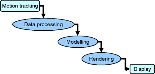
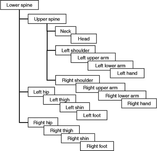
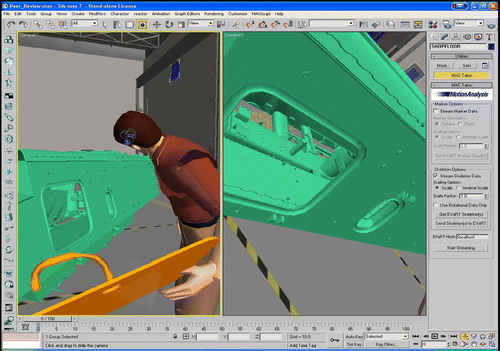
The overall system design is conceptually illustrated in Figure in the form of dataflow. The data from the motion-tracking system are in the format of Hierarchical Translations and Rotations, representing the skeleton movement based on a hierarchical tree structure. Here, a skeleton is a hierarchical structure of points, vectors and distances, which is created in 3D Studio MAX to represent a human or an object. For example, in the case of a human performer, the 3D location of the base of the spine (Lower Spine as shown in Figure ) is attached with an x, y, z coordinate, together with a vector towards the middle of the back and a distance along that vector defining the mid-back point (Upper Spine). The mid-back point has the same data structure, thereby defining the neck point (Neck), and so forth. The coordinates of a complete human model are shown in Figure .
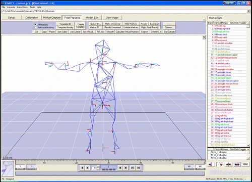
For robust tracking in immersive simulations, markers attached to a human performer or an object are arranged hierarchically and given unique IDs based on their relative locations to adjacent markers. Once the marker hierarchy is created, it is applied to a long data stream where the performer or object goes through an entire course of normal and extreme motions. The skeleton model illustrated in Figure is created in 3D Studio MAX and imported into EVaRT. It is then associated and linked to the predefined set of tracked markers and linkages on the human performer.
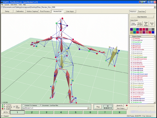
In the APP and training system, a performer is allowed for immersive interactions in the VR environment. The motions of the performer and the manipulated objects are tracked in real time. Wearing a head-mounted display, the performer (the first person in the VR environment) has a first-person point of view that allows him/her to observe and navigate an assembly cell directly via a computer-generated workspace, e.g. unfinished assemblies, tools and his/her own hands or feet. For the purpose of training and supervision, a third-person point of view of a supervisor is rendered side-by-side (as shown in Figure ). For APP and analysis, the performer's motion is recorded such that it can be used to generate a set of assembly sequences later, assuming that the performer is a skilful assembly operator. It can also be replayed independently of the motion-tracking system at a later stage for the purpose of trouble shooting. A standard movie-capturing tool is used to produce a final fixed-view recording for both training and planning purposes. In addition, the first-person point of view of the performer can be accessed to allow designers to look at the work environment from the performer's perspective. Thus, various ergonomic analyses, such as human comfort and workplace safety, can be assessed for better assembly cell design.
5. Experimental results
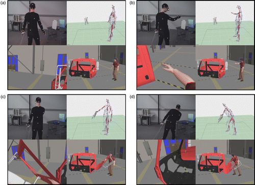
The concept and methodology have been implemented by integrating a motion-tracking system with 3D Studio MAX through EVaRT. A series of experiments have also been successfully performed. Figure shows four sets of screen shots of a truck assembly process. For each set of screen shots, the upper-left is the human performer in action with markers attached and the stereo goggle amounted. The upper-right is the skeleton model and the marker set presentation in EVaRT. The lower-left is the scene seen through the first-person point of view, and the lower-right is the scene from the third-person point of view, both displayed in 3D Studio MAX.
According to the experimental results, it can be seen that driven by the real-time tracking data, the motion of a 3D human avatar in the virtual assembly cell closely represents that of the human performer in the real world during the assembly operations. The first-person point of view allows the human performer to see in the virtual environment, such as his own hand (Figure (b)), the part or tool that he is manipulating (Figure (c)) and the inside view of the cab (Figure (d)). At the same time, the third-person point of view is displayed to allow an instructor to supervise and guide the assembly training process. The whole assembly process is recorded for generating an optimal assembly plan based on subsequent analyses.
It is worth mentioning that the developed prototype system distinguishes itself in several aspects. First, the system is reconfigurable. It can be set up to track large volumes, e.g. a half of a football field, with 32 cameras; or it can be used to capture the fine nuances of human facial motions with three to six cameras. Second, the system is accurate. The current setup has a tracking volume of 4 × 5 × 2 m3, and it can resolve the centroid of a marker to an accuracy of ± 2 mm. Additional markers can be added readily to augment the accuracy and reliability. Third, it is portable. The whole system can be moved to a new location and set up in about 1 day. Finally, the system is reliable, it only employs optically reflective markers for motion tracking, and thus is unaffected by magnetic interference, if any.
The motion-tracking data can also be used for identifying a feasible assembly sequence based on a human performer's practical knowledge, assuming that the performer is competent and skilful.
6. Interactive APP
The VR-assistant environment can be extended to APP, where the assembly sequence of a mechanical product can be determined interactively by a skilful human operator and a computerised decision system. By keeping human being in the loop, it is possible for the system to deal with more complex assembly problems, especially for disassembly of end-of-service products in which the digital designs are unavailable. In this section, we intend to present basic ideas, a function block-enabled approach and some preliminary findings of this on-going research on assembly and disassembly process planning, as the continuation of the motion-tracking-based approach. As the topic in this section differs significantly from those in the previous sections, it is intended to limit the scope to an introduction, leaving details of this part to be reported separately.
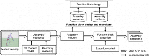
Figure illustrates the conceptual architecture of a motion-tracking-based and function-block-enabled APP system. Within the context, the assembly sequence of a given product is determined by a skilful human operator whose assembly know-how is tracked and analysed against the 3D model of the product. Compared with a purely computer-based assembly sequencing method, our approach combines human tactic knowledge and computer power to generate a feasible solution. It is more effective when an assembly structure is complex. The generated assembly sequence is then mapped to a list of assembly features, such as placing, inserting and riveting as listed in Table . The needed assembly operations of each assembly feature are defined in a matching function block, ready for execution, for example, by a robot. These function blocks are knowledgeable of how to assemble the assembly features. Their functionalities are defined by a set of embedded internal algorithms.
Table 1 Typical assembly features.
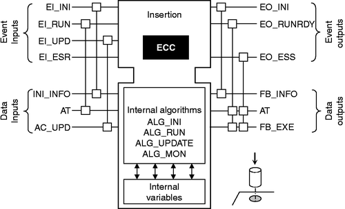
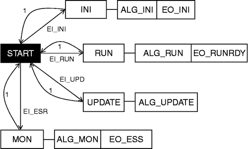
In other words, a function block is a programmable functional unit based on an explicit event-driven model. Under control of an execution control chart (ECC; a finite state machine), the function block provides data flow with its own data structure that can be manipulated by one or more internal embedded algorithms. Figure shows the structure of a basic function block for the inserting assembly feature. Its ECC defines the invocation relationship between the arriving events and internal algorithms (Figure ). The task of insertion consists of picking up a part like a pin, and inserting it into a hole. By defining a series of manipulator's end-effector positions, we can describe the task as a sequence of manipulator's moves and actions related to this ordered positions. Having known the position and orientation of the pin and hole, we can identify and wrap into the Insertion function block the generic path movements for an insertion task.
The structural relationship shown in Figure can also be expressed in the textual syntax below, more readable to human designers:
-
Function_Block INSERTION
-
Event_Input
-
EI_INI with INI_INFO;
-
EI_RUN with AT;
-
EI_UPD with AC_UPD;
-
EI_ESR;
-
End_Event
-
Event_Output
-
EO_INI with FB_INFO;
-
EO_RUNRDY with AT, FB_EXE;
-
EO_ESS with AT, FB_EXE;
-
End_Event
-
Var_Input
-
INI_INFO: vector;
-
AT: float;
-
AC_UPD: vector;
-
End_Var
-
Var_Output
-
FB_INFO: vector;
-
AT: float;
-
FB_EXE: vector;
-
End_Var
-
Algorithm
-
ALG_INI;
-
ALG_RUN;
-
ALG_UPDATE;
-
ALG_MON;
-
End_Algorithm
-
End_Function_Block
The algorithm ALG_RUN implements the following pin-inserting operations, if the operations are to be done by a robot.
Move P1 Approach pin
Move P2 Move over pin
Grasp Grasp the pin
Move p3 Lift it vertically
Move p4 Approach hole at the angle
Move p5 Stop on contact with hole
Move P6 Stand the pin up
Move P7 Insert the pin
Release Let go of the pin
Move P8 Move away
While the internal algorithms are developed in Java, the pseudo codes of the four algorithms of the Insertion function block are provided below for the ease of understanding. For more details on function block design, readers are referred to Keshavarzmanesh et al. (Citation2010).
-
Algorithm ALG_INI(){
-
01 open assembly feature database
-
02 read assembly_time
-
03 collect data from ARNG (part_coodination_orientation)
-
04 set these data to corresponding internal variables
-
05 generate robot path plan
-
06 calculate travel speed
-
07 return assembly_condition, robot_path, travel_speed
-
}
-
Algorithm ALG_RUN( ){
-
01 Insertion.run (robot operating code)
-
02 return AT
-
}
-
Algorithm ALG_UPDATE( ){
-
01 update the assembly_condition received from AC_UPD
-
02 generate robot_path
-
03 return assembly_condition, tool_path
-
}
-
Algorithm ALG_MON(){
-
01 collect and calculate function block execution procedure
-
02 collect assembly condition parameters
-
03 set FB execution condition and assembly condition parameters to Vector FB_EXE
-
04 return FB_EXE
-
}
7. Conclusions
This research incorporates real-time motion-tracking techniques into virtual assembly cell models, thus allowing live human participation and testing towards APP and training. The advancement in motion tracking provides many advantages, including more realistic modelling, better planning of an operator's actions and movements, precise task duration data from real-time simulation, the ability to capture the viewpoint of a human performer in the simulation, generation of accurate ergonomic data for safety planning and reduced error rates and idle time during assembly operations. Moreover, in addition to conventional assembly sequence generation methods based on CAD geometry reasoning and precedent constraints, the motion-tracking-based APP approach is capable of capturing the real assembly sequence of an assembly job performed by a skilful human operator via motion tracking. This is especially true in planning disassembly operations of end-of-service products when their design data are not digitally available. Since the paths of components during assembly and disassembly can be captured together with their positions and orientations, a feasible and practical (dis)assembly plan can be generated by analysing the captured motion data. The (dis) assembly plan, which is further mapped into a set of function blocks with embedded processing algorithms, can be readily executed by a robot. It is expected that the reported approach can streamline the operation planning process from design to control, while involving human being in the loop of decision making. It contributes towards a sustainable and adaptive manufacturing environment.
Our future plan is to further extend the VR-assistant environment to a functional system that allows interactive APP involving a skilful human assembly operator. Research efforts will also be given to function blocks development that can eventually be used for robot control for assembly or disassembly operations. If an assembly process plan can be converted to function blocks and used for robot control directly, significant time saving in robot programming and consistent assembly quality assurance can be achieved.
Our current work and setup can also be extended to other applications, such as assembly cell design, workplace ergonomic analysis and human factors in assembly.
Acknowledgements
This research was partially supported by National Research Council of Canada. The authors would like to thank Steve Kruithof for his support to the research work.
Additional information
Notes on contributors
Xiaoyu Yang
1Notes
References
- Bi , Z.M. , Wang , L. and Lang , S.Y.T. 2007 . Current status of reconfigurable assembly systems . International Journal of Manufacturing Research , 2 ( 3 ) : 303 – 325 .
- Choi , W. 2004 . “ A development and evaluation of reactive motion capture system with haptic feedback ” . In Proceedings of the 6th IEEE international conference on Automatic Face and Gesture Recognition , Seoul, Korea Vol. 4 , 851 – 856 .
- Chryssolouris , G. 2000 . A virtual reality-based experimentation environment for the verification of human-related factors in assembly processes . Robotics and Computer Integrated Manufacturing , 16 : 267 – 276 .
- Cortesao , R. 2004 . Data fusion for robotic assembly tasks based on human skills . IEEE Transactions on Robotics , 20 ( 6 ) : 941 – 952 .
- Dai , F. 1998 . Virtual reality for industrial applications , New York : Springer-Verlag .
- De Lit , P. and Delchambre , A. 2003 . Integrated design of a product family and its assembly system , 1st ed. , Norwell, MA : Kluwer Academic Publishers .
- De Mello , H.L.S. and Sanderson , A.C. 1991 . “ Representations for assembly sequences ” . In Computer-aided mechanical assembly planning , Edited by: De Mello , H.L.S. and Lee , S. 129 – 162 . Norwell, MA : Kluwer Academic Publishers .
- Delchambre , A. 1996 . CAD method for industrial assembly: concurrent design of products, equipment, and control systems , Hoboken, NJ, USA : John Wiley & Sons Ltd .
- Edmondson , N.F. and Redford , A.H. 2002 . Generic flexible assembly system design . Assembly Automation , 22 : 139 – 152 .
- Garbaya , S. , Coiffet , P.H. and Blazevic , P. 2003 . “ Experiments of assembly planning in virtual environment ” . In Proceedings of IEEE international conference on Assembly and Task Planning , Besancon, France 85 – 89 .
- Heilala , F. and Voho , P. 2001 . Modular reconfigurable flexible final assembly systems . Assembly Automation , 21 ( 1 ) : 20 – 28 .
- Henderson, S., 2004. Optimal configuration of human motion tracking systems – a systems engineering approach. Report of NASA Faculty Fellowship Program
- Henrioud , J.M. and Bourjault , A. 1991 . “ LEGA: a computer-aided generator of assembly plans ” . In Computer-aided mechanical assembly planning , 191 – 215 . Norwell, MA : Kluwer Academic Publishers .
- Hirai , S. 1998 . Transferring human motion to mechanical manipulator in insertion of deformable tubes . Robotics and Mechatronics , 10 ( 3 ) : 209 – 213 .
- Hoffman , R.L. 1989 . “ Automated assembly in a CSG domain ” . In Proceedings of IEEE international conference on Robotics and Automation 210 – 215 .
- Hornung , A. , Sar-Dessai , S. and Kobbelt , L. 2005 . Self-calibration optical motion tracking for articulated bodies . IEEE Virtual Reality , 5 : 75 – 82 .
- Jayaram , S. 1999 . VADE: a virtual assembly design environment . IEEE Computer Graphics and Applications , 19 ( 6 ) : 44 – 50 .
- Jones , R.E. , Wilson , R.H. and Calton , T.L. 1998 . On constraints in assembly planning . IEEE Transactions on Robotics and Automation , 14 ( 6 ) : 849 – 863 .
- Kaufman , S.G. , Wilson , R.H. and Jones , R. 1996 . “ The Archimedes 2 mechanical assembly planning system ” . In Proceedings of IEEE international conference on Robotics and Automation , Minneapolis, MN 3361 – 3368 .
- Keshavan , K. 1993 . “ Current practices of assembly planning in industry ” . In Proceedings of IEEE ICRA workshop on Assembly and Task Planning , Atlanta, GA
- Keshavarzmanesh , S. , Wang , L. and Feng , H.-Y. 2010 . Design and simulation of an adaptive and collaborative assembly cell . International Journal of Manufacturing Research , 5 ( 1 ) : 102 – 119 .
- Ko , H. and Lee , K. 1989 . Automatic assembly procedure generation from mating conditions . Computer-Aided Design , 19 ( 1 ) : 3 – 10 .
- Kong , S.H. 2006 . An agent-based collaborative assembly process planning system . International Journal of Advanced Manufacturing Technology , 28 : 176 – 183 .
- Leon , J.C. , Gangiaga , U. and Dupont , D. 2001 . “ Modelling flexible parts for virtual reality assembly simulations which interact with their environment ” . In Proceedings of IEEE international conference on Shape Modelling , Genova, Italy 335 – 344 .
- Loock , A. and Schomer , E. 2001 . “ A virtual environment for interactive assembly simulation – from rigid bodies to deformable cables ” . In Conference SCI , Orlando, FL, USA
- Mattikalli , R. , Baraff , D. and Khosla , P. 1996 . Finding all stable orientations of assemblies with friction . IEEE Transactions on Robotics and Automation , 12 : 290 – 301 .
- Mikchevitch , A. , Leon , J.C. and Gouskov , A. 2003 . “ Path planning for flexible components using a virtual reality environment ” . In Proceedings of IEEE international conference on Assembly and Task Planning , Besancon, France 247 – 252 .
- Molnar , J. 1997 . “ Immersion of a live individual combatant into a virtual battlespace ” . In Proceedings of the 14th annual AESS/IEEE Dayton Section Symposium , Fairborn, OH, USA 27 – 34 .
- Nevins , J.L. and Whitney , D.E. 1980 . Assembly research . Automatic , 16 : 595 – 613 .
- Nof , S.Y. , Wilhelm , W.E. and Warnecke , H.J. 1997 . Industrial assembly , 1st ed. , Great Britain : Chapman & Hall .
- Richard , P.P. 1981 . Robot manipulators, mathematics, programming and control , Hoboken, NJ, USA : MIT Press .
- Sawik , T. 1999 . Production planning and scheduling in flexible assembly systems , Berlin : Springer-Verlag .
- Sunil , V.B. and Pande , S. 2004 . WebROBOT: Internet based robotic assembly planning system . Computers in Industry , 54 : 191 – 207 .
- You , C.F. , Tsou , P.J. and Yeh , S.C. 2007 . Collaborative design for an assembly via the Internet . International Journal of Advanced Manufacturing Technology , 31 : 1217 – 1222 .
- Yu , Q. and Terzopoulos , D. 1999 . Synthetic motion capture for interactive virtual worlds . The Visual Computer , 15 ( 7/8 ) : 337 – 394 .
- Zauner , J. , Haller , M. and Brandl , A. 2003 . “ Authoring of a mixed reality assembly instructor for hierarchical structures ” . In Proceedings of the 2nd IEEE international symposium on Mixed and Augmented Reality (ISMAR'03)
- Zha , X.F. , Lim , S.Y.E. and Lu , W.F. 2003 . A knowledge intensive multi-agent system for cooperative collaborative assembly modeling and process planning . Journal of Integrated Design and Process Science , 7 ( 1 ) : 99 – 122 .
- Zhang , W.J. and Xie , S.Q. 2007 . Agent technology for collaborative process planning: a review . International Journal of Advanced Manufacturing Technology , 32 : 315 – 325 .
