Abstract
This paper deals with an implementation of voltage and frequency controller (VFC) for isolated asynchronous generator-based three-phase autonomous wind energy conversion system. The focus of the proposed work is to provide a feasible solution for rural communities to serve their electricity needs. The least mean square algorithm is used for the extraction of active and reactive power components of the load currents. A three-leg voltage-sourced converter with a battery energy storage system is used as a VFC. The control algorithm is implemented using a digital signal processor. The steady-state and dynamic performances of VFC are demonstrated through test results under static and dynamic loads.
1. Introduction
With the ever-increasing concern over energy crisis, the impacts of renewable energy programmes are increasing rapidly. The penetration of wind power in such renewable energy programmes is ahead. By the end of 2009, the world wind energy-based electricity generation has reached 340 TWh, 2% of the total global electricity consumption (World Wide Wind Energy Report Citation2009). There are many regions in the world such as islands and offshore places where the grid connection is either impossible or unduly expensive. For such applications, autonomous wind energy conversion systems (AWECSs) proved promising (Johnson Citation2006). In India, there is scarcity of electricity in many regions especially remote places in which even grid connections are available, but the availability of electrical power is for only few hours a day. The main consumption of electrical power in such remote places is in submersible pumps, flourmills, household appliances such as mixer, grinder, television, computers and energy-efficient lightings. Broadly, these loads may be classified as linear, nonlinear and dynamic loads. Most of the electrical power is consumed by squirrel-cage induction motor driven loads. In such places, AWECS may be a viable alternative. However, wind energy is greatly influenced by weather conditions and diurnal variations, and has the large uncertainty and strong fluctuations, which makes wind an intermittent power source (Kaltschmitt et al. Citation2007). Therefore, it is unable to regulate the generated power as per the consumer demands. In view of the above, a means of energy storage is essential to bridge the gap between demand and supply. In the literature, a number of solutions have been proposed for the storage of energy using battery energy storage system (BESS), pumped storage system, super capacitors and superconducting magnetic energy storage systems, etc. (Miranda et al. Citation1999, Agbossou et al. Citation2004, Suul et al. Citation2008, Ummels et al. Citation2009, Ali et al. Citation2010, Allegre et al. Citation2010, CitationApaefthymiou et al. future). However, considering the initial investment, control complexity and size, BESS has been proved to be better for AWECS. The size of BESS depends on the rating of AWECS, wind forecast and the diversity of the connected loads. The diversity of loads may play a major role in optimising the size of BESS for applications like electrifying villages. The submersible pumps are in operation at daytime or in late night hours, however, the penetrations of loads for household appliances are in the morning or evening.
Isolated asynchronous generators (IAGs) are in practice with both in fixed speed and variable speed AWECS due to ruggedness, brushless construction, less maintenance requirement, high power/weight ratio, inexpensive and self short-circuit protection (Wang and Lee Citation1997). However, it suffers from poor voltage and frequency regulation characteristics (Malik and Haque Citation1986). The IAGs in fixed speed operation and BESS are reported with voltage and frequency controller (VFC; Bonert and Hoops Citation1990, Lopes Luiz and Almeida Rogerio Citation2006, Singh and Kasal Citation2008a, Citation2008bSingh and Kasal 2008a, 2008b). Bonert and Hoops (Citation1990) have proposed an electronic impedance controller for regulating the voltage and frequency of IAG using a thyrsitor-controlled rectifier followed by a pulse width modulated (PWM)-controlled chopper feeding resistive loads. However, this scheme has suffered from poor efficiency due to large excitation capacitances and dump load. Furthermore, the load demand higher than the generated power cannot be fed by such system. Lopes Luiz and Almeida Rogerio (Citation2006) have reported a synchronous reference frame theory based on VFC for IAG-based AWECS using voltage-sourced converter (VSC) and BESS. In this simulation study, the authors have also used a thyristor converter-fed dump load for consuming excess active power, when the BESS is fully charged. Singh and Solanki (Citation2009) have reported a VFC for IAG-based AWECS using three single-phase VSC and BESS for three-phase four-wire system. The VFC control scheme has been realised using the extraction of amplitude of load currents. Most of these attempts are limited to simulation studies. However, the practical implementation of fixed speed IAG-based AWECS is not reported so far in the literature.
This paper deals with the development of VFC for IAG-based AWECS. A three-leg VSC with BESS is used as a VFC. The VFC control algorithm is realised using an adaptive linear neuron (ADALINE; Widrow et al. Citation1975, Djaffar et al. Citation2007, Singh et al. Citation2007, Cirrincione et al. Citation2009, Singh and Solanki Citation2009). The least mean square (LMS) algorithm is used to extract the active and reactive power component of the load currents. During high wind and for low-load periods, the BESS absorbs the surplus-generated power to keep IAG frequency constant. Similarly, during low wind and for high-load periods, the BESS supplies the deficit load power to keep IAG frequency constant. A prototype of VFC is developed using a 3.7 kW IAG driven by an AC motor drive simulating the wind turbine, a VSC and a 420 V battery bank. The performance of the VFC is tested with the non-linear load (three-phase diode-rectifier feeding R–L load) and a dynamic load (1.5 kW, 4-pole, 230 V star-connected induction motor).
2. System configuration
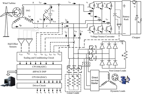
Figure shows the schematic diagram of the proposed IAG-based AWECS. A 3.7 kW, 4-pole asynchronous generator coupled with a variable frequency AC motor drive is used to realise a wind turbine. The detailed specifications of both machines are given in the Appendix. A VSC is connected at the point of common coupling (PCC) through interfacing inductors. The direct current (DC) link of VSC is connected to a battery bank. Two Hall effect voltage sensors (LEM CV3-1500) are used to sense the line voltages v AB and v BC. These sensed line voltages are used to estimate phase voltages (v A, v B and v C). Two Hall effect current sensors (ABB EL50BB) are used to sense the source currents (i sA and i sB). The third-phase source current (i sC) is estimated using these two sensed source currents. Two Hall effect current sensors are used to sense the load currents (i LA and i LB). The third-phase load current is estimated from these two sensed load currents. One Hall effect voltage sensor (LEM CV3-1500) is used to sense the battery rack voltage. The scaling circuits are designed to use in between the sensed signals and analog-digital converter (ADC) of the digital signal processor (DSP). The control algorithm is realised in the MATLAB environment using real-time blocks. After compilation, programme code is loaded in the DSP to generate the switching signals for insulated gate bipolar transistors (IGBTs) of VSC and a chopper through digital-analog converter (DAC) of DSP. An optocoupler (6N136)-based isolation and amplification circuit is used to drive the IGBT modules of VFC.
3. Operating principle
The voltage and frequency control of IAG-based AWECS depend on exchanging the active and reactive powers at the PCC through VSC. To maintain constant frequency of AWECS during high wind power and of low-load periods, surplus-generated power (difference of generated power and consumer load power) is absorbed in the BESS. Similarly, during low wind power and for high-load periods, the deficit energy is retrieved from the BESS for maintaining the constant frequency of AWECS. The deficit power (difference of consumer load power and generated power) must be supplied from BESS. The IAG needs a reactive power to build and to maintain its terminal voltage. A fixed value delta-connected excitation capacitor is connected at IAG terminals. Due to the nature of load connected at PCC, the reactive power demand changes to regulate the IAG terminal voltage. Therefore, to control the terminal voltage, the VSC supplies or absorbs the required reactive power. A resistive dump load is connected through a chopper at the DC bus, which absorbs the excess power when the battery is fully charged and power generation is more than the connected consumer loads.
4. Design of voltage and frequency controller
The VFC consists of a three-leg current-controlled VSC connected to the PCC through interfacing inductors. The DC link of the VSC is connected to a battery rack to absorb or to deliver the active power to the PCC.
4.1 Terminal capacitors
The IAG draws leading volt–ampere reactive (VAR) for its excitation to establish the terminal voltage. In grid-connected generators, leading VAR is either supplied from the grid itself or locally through the use of terminal capacitors. In the case of autonomous operations of IAG, this demand is always acquired using external capacitors. However, the leading VAR demand to generate the rated terminal voltage is a function of consumer loads and its nature (pf) connected on the load bus at particular IAG speed. In general, the terminal capacitors connected at IAG bus are fixed and VSC provides or absorbs the additional reactive power under changes in input wind speeds and consumer loads to regulate the terminal voltage. Therefore, the choice of an excitation capacitor connected at the generator bus affects the rating of VSC. The selection of terminal capacitors is based on the type and the nature of loads to be connected on AWECS. However, in this implementation, a delta-connected capacitor bank of 4.2 kVAR is used for a 3.7 kW, 4-pole, 50 Hz, IAG.
4.2 Choice of DC bus battery voltage
The DC bus battery voltage of VSC must be greater than twice the peak of the phase voltage at the AC terminals of VSC (Singh et al. Citation2004) for satisfactory operation. Therefore, the minimum DC bus battery voltage required for proper VSC operation is,
4.3 Selection of battery
The battery is an energy storage device and its energy is represented in kilowatt–hours (kWh). The capacity of a battery bank for AWECS is decided based on the wind speed profile at the site and the diversity of the connected loads. Large storage capacity may facilitate better contingency handling, but increases the initial investment, space and maintenance problems. A compromise has been made in selecting the size of battery storage unit. Furthermore, as the required V bb is more than 376 V, the minimum battery rack voltage is kept at 420 V. A battery rack with a capacity of 2.9 kWh is used for the energy storage in this implementation. For the DC bus battery voltage of 420 V, 35 units of 12 V, 7 Ah batteries are used in series connection.
4.4 AC inductor
The choice of an AC inductor is a function of permissible current ripple (i pp), DC bus voltage (V bb) and modulating frequency (f m) of VSC (Singh et al. Citation2004),
5. Control algorithm
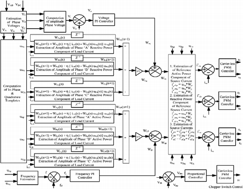
Figure shows the block diagram of the proposed control algorithm for VFC. The VFC serves two basic objectives of voltage and frequency control along with the function of a load leveller, a load balancer and a harmonic eliminator. For voltage control, the VFC supplies or absorbs reactive power through a three-leg VSC. For frequency control, the VFC absorbs or supplies the active power to the PCC through VSC and BESS. To achieve these objectives, the reference source currents are controlled through the switching of VSC. To estimate the reference source currents, the following basic equations are used in this algorithm.
5.1 Computation of phase voltages
These line voltages v AB and v BC are sensed at IAG terminals and phase voltages v A, v B and v C are computed as (Akagi et al. Citation2007),
The computed voltages are filtered using band pass filter to separate the high-frequency noise present in the sensed voltages.
5.2 Computation of in-phase and quadrature unit templates
The in-phase unit templates are derived using amplitude of voltage V t at IAG terminals and instantaneous phase voltages at nth sampling instant as,
5.3 Estimation of active and reactive power weights of load currents
The weights of active power components of three-phase load currents are estimated with three ADALINEs trained using LMS algorithm (Singh and Solanki Citation2009). The weights (W Ap, W Bp and W Cp) are estimated as follows:
The practical value of η (step size parameter) lies in between 0.001 and 1. It controls the convergence characteristics and the accuracy of estimation. The high value of η increases the rate of convergence but leads to inaccurate estimation. On the other hand, a low value of η decreases the rate of convergence with improved estimation. The best trade-off value of η used is 0.1 in this implementation.
5.4 Estimation of active power component of reference source currents
The weights or the amplitude of active power component of reference source currents are estimated from the difference of the output of the frequency proportional–integral (PI) regulator (W fp) and average weight of load currents (W Lp). The AWECS frequency is estimated using enhanced phase-locked loop (Karimi-Ghartemani et al. Citation2005). The frequency error at the (n+1)th sampling time is given as
Therefore, the average weight for fundamental active power component of the reference source currents is as,
Three-phase fundamental active power component of the reference source currents are computed as,
5.5 Estimation of reactive power component of reference source currents
The average weight (W Lq) of the fundamental reactive power component of the load currents is subtracted from the voltage PI controller output (W vq) to estimate the weight of the fundamental reactive power component of the reference source currents. The AC voltage error at the (n+1)th sampling instant is given as,
The output of the voltage PI controller is to maintain a constant AC terminal voltage. The terminal voltage is a function of the reactive power. Therefore, to regulate the voltage, the output of voltage PI controller in terms of the weight of reactive power component of the source currents at the (n+1)th sampling instant is expressed as,
Therefore, the average weight of fundamental reactive power component of the reference source currents is given as,
Three-phase fundamental reactive power component of the reference source currents is given as,
5.6 Estimation of fundamental reference source currents
Three-phase fundamental reference source currents are estimated for each phase as the sum of individual-phase fundamental reference active power component of the source current and fundamental reference reactive power component of the source current,
5.7 Carrier-less PWM controller
Three-phase reference source currents (,
and
) computed in Equation (Equation21
) are compared with sensed source currents (i
sA, i
sB and i
sC). Three independent carrier-less PWM controllers are used for the three legs of VSC. The current tolerance limit of 0.1 A is selected in this implementation. When the current error for individual phase falls below lower limit, the upper switch is switched on and the lower switch is switched off. The moment the current error exceeds above the upper limit, negative bus switch is switched on keeping positive bus switched off.
5.8 Chopper control
A step-down chopper is connected at DC link that is feeding a resistive dump load. Under normal conditions, the battery is partially charged and a chopper switch is kept switched off through controller action. For controlling the operation of chopper switch, the battery rack voltage (V
bb) is sensed and compared with the reference battery rack () voltage. The reference battery rack voltage (13.5 × 35 = 472.5 V) is decided based on maximum battery rack voltage under fully charged condition. The error voltage (V
bbe) is amplified using a proportional gain and then it is compared and fed to a PWM controller to generate the gating signal for the chopper switch.
6. Results and discussion
The proposed AWECS is targeting the rural community in which most of the consumer loads are for household appliances (linear and nonlinear loads), lighting and for their agricultural needs (squirrel-cage induction motor). However, the most severe loads that may destabilise the operation of AWECS are the nonlinear loads and starting transients of direct on-line (DOL) starter of squirrel-cage induction motor. Therefore, test results are presented to demonstrate the performance of VFC with nonlinear loads and with the starting of an induction motor at different wind speeds (base wind speed is considered to be 12 m/s). The test results are recorded in terms of the generator line voltage (v AB), generator currents (i gA, i gB and i gC), source currents (i sA, i sB and i sC), capacitor currents (i cA, i cB and i cC), three-phase consumer load currents (i LA, i LB and i LC), generated power (P g), battery power (P b), consumer load power (P L), battery voltage (V bb) and battery current (i b). Fluke 43B power analyser and Agilent digital signal oscilloscope (DSO6014A) are used to record these test results.
6.1 Performance of the VFC under nonlinear loads
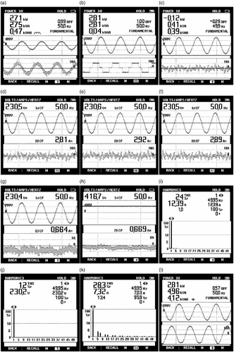
In practice, televisions, computers, power supplies, energy-efficient lighting and variable speed drives are some of the consumer nonlinear loads that affect the power quality. These nonlinear loads are classified as current-sourced harmonic loads (thyrsitor-controlled rectifier-fed loads, current-sourced inverter-fed induction motors and synchronous motors, etc.) or voltage-sourced harmonic loads (switch mode power supplies for television and computer, energy-efficient lightings, voltage source inverter-fed AC drives, etc.). In the laboratory, a three-phase diode-rectifier feeding R–L load is used as a current-sourced harmonic load to test the performance of VFC as a load leveller, a load balancer and a harmonic eliminator along with a VFC. Test results are recorded with the line voltage v AB. Figure (a–c) shows the three-phase generator currents i gA, i gB and i gC. These generator currents are balanced and sinusoidal. Three-phase terminal capacitor currents i cA, i cB and i cC are shown in Figure 3(d–f). Figure (g–i) shows the three-phase source currents i sA, i sB and i sC. Three-phase load currents i LA, i LB and i LC are shown in Figure (j–l). The generator power (P s = 2.71 kW) when the wind speed is 10.81 m/s, load power (P L = 2.81kW) and BESS power (P b = 0.12kW) are shown in Figure (a–c). At this time, the consumer load power demand is more than the generated power and, therefore, the BESS is delivering the deficit load power (difference between load power demand and generated power). Figure 4(d–f) shows the three-phase VSC currents i vscA, i vscB and i vscC. Figure (g–h) shows the battery discharge current i b with line voltage v AB and DC bus battery voltage v bb. The harmonic spectra of i gA, v AB and i LA are shown in Figure 4(i–k). These total harmonic distortions of generator current and voltage are within IEEE-519 specified limits. Figure (l) shows the generator power P g (2.89 kW), generator kVA (4.96 kVA) and reactive power demand (4.12 kVAR) of IAG at rated terminal voltage.
Figure 3 Steady-state performance of the VFC at constant wind speed (10.81 m/s) and balanced nonlinear loads: (a) v AB and i gA; (b) v AB and i gB; (c) v AB and i gC; (d) v AB and i cA; (e) v AB and i cB; (f) v AB and i cC; (g) v AB and i sA; (h) v AB and i sB; (i) v AB and i sC; (j) v AB and i LA; (k) v AB and i LB; (l) v AB and i LC.
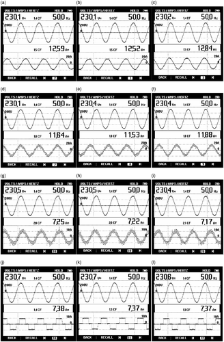
Figure 4 Steady-state performance of the VFC at constant wind speed (10.81 m/s) and balanced nonlinear loads: (a) v AB and P s; (b) v AB and P L; (c) v AB and P b; (d) v AB and i vscA; (e) v AB and i vscB; (f) v AB and i vscC; (g) v AB and i b; (h) v bb and i b; (i) harmonic spectrum of i gA; (j) harmonic spectrum of v AB; (k) harmonic spectrum of i LA; (l) v AB and P g.
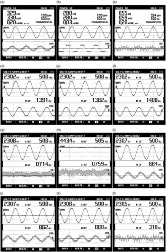
Test results are also recorded with the change in input power while the consumer load power is constant. Figure (a–c) shows the P g, P L and P b. The generated power (3.29 kW when the speed is 11.53 m/s) is more than the load power (2.80 kW) and, therefore, surplus-generated power (difference of generated power and load power, i.e. 0.55 kW) is absorbed in the BESS. Three-phase generator currents i gA, i gB and i gC are shown in Figure 5(d–f). There is a change in the amplitude of these currents due to rise in the generated power. The battery charging current i b with line voltage v AB and DC bus battery voltage V bb are shown in Figure (g–h), respectively. Figure 5(i–k) shows the three-phase source currents under these conditions. The change in VSC current i vscA is shown in Figure (l).
Figure 5 Steady-state performance of the VFC at wind speed (11.53 m/s) and balanced nonlinear loads: (a) v AB and P s; (b) v AB and P L; (c) v AB and P b; (d) v AB and i gA; (e) v AB and i gB; (f) v AB and i gC; (g) v AB and i b; (h) v bb and i b; (i) v AB and i sA; (j) v AB and i sB; (k) v AB and i sC; (l) v AB and i vscC.
6.2 Performance of VFC feeding dynamic loads
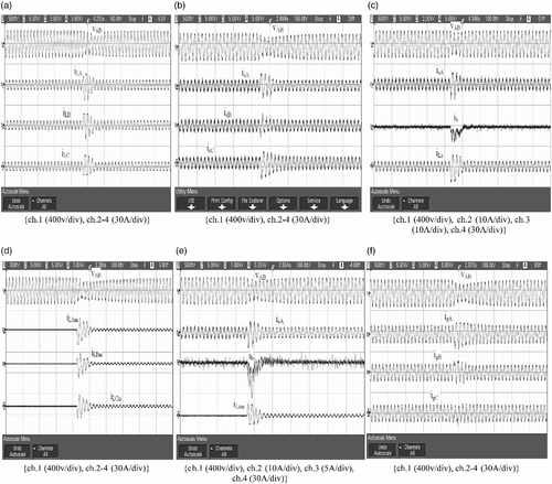
The most severe transients with squirrel-cage induction motor loads occurred during its DOL starting. The starting current of an induction motor is many times the rated current with a DOL starter. A 1.5 kW, 2-pole, 230 V, 50 Hz Y-connected three-phase squirrel-cage induction motor is used as a dynamic load. A DOL starter is used to start this motor. Under running conditions, these loads behave like a lagging power factor loads. Therefore, test waveforms are recorded during the starting of the induction motor to demonstrate the stability of VFC under these extreme transients. Figure (a) shows v AB, i LA, i LB and i LC during switch on of an induction motor. A 2 kW unity power factor three-phase load is already connected on load bus before the starting of an induction motor. A large change in load currents is observed at this moment. At the same time a small dip in terminal voltage is observed which is settled to its reference within a few cycles. Figure (b) shows the v AB, i sA, i sB and i sC during load perturbations. A small rise in these source currents is also observed due to sharp rise in load currents, which are settled within few cycles. The change in v AB, i sA, i b and i LA during the starting of the induction motor is shown in Figure (c). It is observed that the battery is charged before switching on the induction motor. The moment an induction motor is switched on, there is a sharp discharge current flow through the battery due to the control action of VFC. Figure (d) shows recorded waveforms of inrush currents of the induction motor (i LAm, i LBm and i LCm) with the line voltage v AB. Test waveforms of v AB, i sA, i b and i LAm are given in Figure (e) to demonstrate the effect of switching transients of an induction motor. Figure (f) shows the generator currents igA, igB and igC during these conditions. It is observed that the change in generator currents is very small than the perturbations in load currents. From these test results, it is shown that the VFC is found stable even under large perturbations in load currents.
7. Conclusion
A VFC for IAG-based AWECS has been developed to feed nonlinear and dynamic loads. The LMS algorithm-based load current extraction technique has been used in VFC for voltage and frequency control. It has eliminated the use of any low-pass filter in the control algorithm, which has improved the dynamic performance of the VFC. The stability of VFC has been verified through test results with switching of dynamic loads. The VFC has also performed the function of a load leveller, a load balancer and a harmonic eliminator.
References
- Agbossou , K. 2004 . Performance of a stand-alone renewable energy system based on energy storage as hydrogen . IEEE Transactions on Energy Conversion , 19 ( 3 ) : 633 – 640 .
- Akagi , H. , Watanabe , E.H. and Aredes , M. 2007 . Instantaneous power theory and applications to power conditioning , Hoboken, NJ : Wiley-Inter-Science, IEEE Press .
- Ali , M.H. , Bin , W. and Dougal , R.A. 2010 . An overview of SMES applications in power and energy systems . IEEE Transactions on Sustainable Energy , 1 ( 1 ) : 38 – 47 .
- Allegre , A.L. 2010 . Reduced-scale-power hardware-in-the-loop simulation of an innovative subway . IEEE Transactions on Industrial Electronics , 57 ( 4 ) : 1175 – 1185 .
- Apaefthymiou , V. A wind-hydro-pumped storage station leading to high RES penetration in the autonomous island system of Ikaria . IEEE Transactions on Sustainable Energy , to be published
- Bonert , R. and Hoops , G. 1990 . Stand alone induction generator with terminal impedance controller and no turbine controls . IEEE Transactions on Energy Conversion , 5 ( 1 ) : 28 – 31 .
- Cirrincione , M. 2009 . Current harmonic compensation by a single-phase shunt active power filter controlled by adaptive neural filtering . IEEE Transactions on Industrial Electronics , 56 ( 8 ) : 3128 – 3143 .
- Djaffar , O.A. 2007 . A unified artificial neural network architecture for active power filters . IEEE Transactions on Industrial Electronics , 54 ( 1 ) : 61 – 76 .
- Johnson, G.L., 2006. Wind energy systems, Electronic Edition. Available from: http://eece.ksu.edu/∼gjohnson/Windbook.pdf [Accessed October 2006]
- Kaltschmitt , M. , Streicher , W. and Wiese , A. 2007 . Renewable energy, technology and environment, economics , Berlin Heidelberg : Springer-Verlag .
- Karimi-Ghartemani , M. , Iravani , M.R. and Katiraei , F. 2005 . Extraction of signals for harmonics, reactive current and network unbalance compensation . Proceedings of IEE Generation, Transmission and Distribution , 152 ( 1 ) : 137 – 145 .
- Lopes Luiz , A.C. and Almeida Rogerio , G. 2006 . Wind-driven self excited induction generator with voltage and frequency regulated by a reduced rating voltage source inverter . IEEE Transactions on Energy Conversion , 21 ( 2 ) : 297 – 304 .
- Malik , N.H. and Haque , S.E. 1986 . Steady state analysis and performance of an isolated self excited induction generator . IEEE Transactions on Energy Conversion , EC-1 ( 3 ) : 134 – 139 .
- Miranda , M.S. , Lyra , R.O.C. and Silva , S.R. 1999 . An alternative isolated wind electric pumping system using induction machines . IEEE Transactions on Energy Conversion , 14 ( 4 ) : 1611 – 1616 .
- Singh , B. and Kasal , G.K. 2008a . Solid state voltage and frequency controller for a standalone wind power generating system . IEEE Transactions on Power Electronics , 23 ( 3 ) : 1170 – 1177 .
- Singh , B. and Kasal , G.K. 2008b . Voltage and frequency controller for a three phase four – wire autonomous wind energy conversion system . IEEE Transactions on Energy Conversion , 23 ( 2 ) : 509 – 518 .
- Singh , B. and Solanki , J. 2009 . An implementation of an adaptive control algorithm for a three-phase shunt active filter . IEEE Transactions on Industrial Electronics , 56 ( 8 ) : 2811 – 2820 .
- Singh , B. , Verma , V. and Solanki , J. 2007 . Neural network-based selective compensation of current quality problems in distribution system . IEEE Transactions on Industrial Electronics , 54 ( 1 ) : 53 – 60 .
- Singh , B.N. 2004 . Design, simulation and implementation of three pole/four pole topologies for active filters . IEE Proceeding on Electric Power Applications , 151 ( 4 ) : 467 – 476 .
- Suul , J.A. , Uhlen , K. and Undeland , T. 2008 . “ Wind power integration in isolated grids enabled by variable speed pumped storage hydropower plant ” . In IEEE international conference ICSET 2008 399 – 404 . 24–27 November 2008, SMU Conference Centre, Singapore
- The World Wide Wind Energy Report, 2009. p. 5. Available from: http://www.wwindea.org/home/images/stories/worldwindenergyreport2009_s.pdf
- Ummels , B.C. 2009 . Comparison of integration solutions for wind power in the netherlands . IET Renewable Power Generation , 3 ( 3 ) : 279 – 292 .
- Wang , L. and Lee , C.H. 1997 . A novel analysis on the performance of an isolated self-excited induction generator . IEEE Transactions on Energy Conversion , EC-12 ( 2 ) : 109 – 117 .
- Widrow , B. , McCool , J.M. and Ball , M. 1975 . The complex LMS algorithm . IEEE Proceedings , 63 : 719 – 720 .
Appendix
IAG data: 3.7 kW, 230 V, 14.5 A, 50 Hz, Y-connected, 4-pole.
Prime-mover data: 3.7 kW, 415 V, 7 A, delta-connected, 4-pole, 1430 rpm, induction motor driven by ABB make AC drive ACS 550-01-015A.
VFC parameters: ready to shelf semikron make voltage source converter 10 kVA Lf = 4 mH, Rf = 0.02 Ω, Cdc = 4000 μF, Kpv = 0.8, Kiv = 0.02, Kpf = 1, Kpif = 0.7.
Battery rack: Vdc = 420 V, 2.9 kWh. The battery rack contains 35 units of 12 V, 7 Ah connected in series.
Induction motor: 1.5 kW, 2-pole, 2890 RPM, 230 V, Y-connected, squirrel-cage machine.
