Abstract
Due to the characteristic that shape memory materials can quickly return to their original shape and have large deformation, such materials can be used as the connection in active disassembly devices. However, existing active disassembly devices typically require two moulding steps and complicated machining processes that result in high manufacturing cost. The active disassembly device based on the proposed decapitated head method has only one moulding step and lower manufacturing cost. Its disassembly mode is local damage disassembly, which can decrease the active disassembly cost and improve disassembly efficiency. This paper describes the active disassembly theory and the design methodology based on the decapitated head method, and then analyses the design criteria and feasibility of this method with a real case study.
1 Introduction
Along with the expanding concept of circular economy and sustainable development, which is rooted in a systems perspective on the interaction of the natural environment and the anthroposphere and focuses on the input–output analysis of material flows transformed by production and consumption, the recycling and disposal requirements of end-of-life electronic products are becoming increasingly strict at home and abroad. At present, the pretreatment of electronic products is mainly by artificial disassembly, the efficiency of which is very low, or by mechanical separation, which may destroy the reusable parts and components. Aiming to solve these problems, some experts have proposed the concept of active disassembly which can improve the efficiency of disassembly and the value of end-of-life products. Recovery and reuse contribute to energy saving and protection of the environment, thus supporting the aims of sustainable development.
Associated with research on smart materials, the method of active disassembly using smart materials (ADSMs) has generated particular interest. ADSM was proposed in 1997 by Dr Joseph Chiodo from Cleaner Electronics Research of Brunel University. ADSM is applied to connection components (such as screws, screw joints and coil springs) by shape memory alloy (SMA) or shape memory polymer (SMP), materials that can return to their original shape in particular environmental conditions. When the external environment is changed, the connector will deform and automatically separate from the connection device. For example, the thread of a screw disappears and the snap fastener curves. This is advantageous for product separation and component recycling (Chiodo et al. Citation1999a, Citation1999b).
Active disassembly technology based on ADSM can be divided into two classes. The first class is the use of SMP for the connection device utilising the advantage that SMP can return quickly to its original shape and has large associated deformation. Examples include SMP snap fasteners, screws and rivets; or making the SMA the driving part used to separate parts and components utilising the advantage that SMAs have large restoring forces when used in such applications as SMA ribbons, coil springs or tubes. Products of this type can be actively disassembled using external triggers. However, the manufacture of these active disassembly devices requires two moulding steps. In the first moulding step, the shape memory material (SMM) is made to the shape after deformation by injection or other approaches. In the second moulding step, the SMM, after being disposed, is heated to the temperature of its reversible phase to soften it. Then this shaped material is forced to the connection state to enable parts and components assembly by mould pressing. Because accuracy control of mould pressing is lower than that of injection, the second moulding step increases costs for improving assembly accuracy, usually accounting for 80% of the total cost and, in addition, the machining processes are complex.
The second class is that in which the active disassembly devices are based on the decapitated head method. With the strength of SMP near the trigger temperature reducing by several orders of magnitude, the SMP material can be made as the active disassembly device directly by pouring or injecting. A driving part is placed between two parts of a product. When the trigger temperature is reached, the strength of the SMP connecting piece reduces sharply and so it can be pulled out by the driving force causing the connection device to fail.
There is no need for a second moulding step in active disassembly devices based on the decapitated head method. The machining processes are simpler and the manufacturing cost is lower than that method requiring two moulding steps, while the disassembly efficiency is much higher. The active disassembly phenomenon of SMP screws based on the decapitated head method is being researched (Chiodo et al. Citation1999a,Citationb). When heated, the SMP screw can be pulled out by the driving force and thus loses its connection function. This phenomenon was identified by Cleaner Electronics Research of Brunel University, but the design method and criteria were not presented. The present paper reports research on the design method of active disassembly devices based on the decapitated head method, and presents the necessary processes and steps.
2 Strength test for SMP materials
For this research, the tensile strength of SMP materials, whose trigger temperature is 70°C, was measured using a Shimadzu tensile testing machine. The specimen was loaded dynamically at ambient temperature, normally 20°C, and the results obtained were that the limit load was 1340 N, the ultimate strength was 64 MPa and the elongation was 4.5%. When heated to 75°C, the specimen began to soften and its strength reduced sharply. The tensile test showed that the limit load of the specimen was 20 N and the ultimate strength was 1 MPa.
From the mechanical properties of SMP materials we know that, at ambient temperature, SMP materials exhibit brittleness. The strength and rigidity are high, and there is no plastic yield stage in the fracture process. When heated to the trigger temperature, these materials will exhibit plasticity, and the strength reduces sharply to about 1/64 of that at ambient temperature. At the trigger temperature, the strength of SMP materials reduces at a faster rate than that of ordinary plastics. Because the modulus of elasticity of SMP materials decreases with increase in temperature, the materials have high modulus of elasticity at low temperature but low modulus of elasticity at high temperature, and this can be exploited in active disassembly devices.
3 Active disassembly theory based on the decapitated head method
An active disassembly device based on the decapitated head method mainly relies on an external driving force to break itself and make the connecting relationship fail. Because the strength and rigidity of SMP are very high at ambient temperature, but reduce sharply near the trigger temperature, SMP can be used to make active disassembly devices. When the product is disassembled, the active disassembly device is pulled out by using drive parts to provide the driving force after strength reduction, and the connecting relationship between components and parts will fail. The strength of SMP near the trigger temperature sharply reduces by several orders of magnitude, so SMP can be used to make active disassembly devices (such as SMP snap fasteners, screws and rivets and so on) which can be used in the connecting parts of products. When heated to the trigger temperature, the active disassembly device will fail in connection with a low driving force because the strength has reduced sharply. Drive parts which offer driving force include SMA ribbons, SMA coil springs or SMA tubes.
4 The active decapitated head method disassembly process
To obtain sufficient driving force, SMA is used to make the shape memory coil spring as a driving part, as shown in Figure . The form applied to parts and components can be chosen with discretion from such components as a normal coil spring, a torsional spring or a leaf spring. However, in order to provide large stroke, a coil spring is preferred in practice.
Figure 1 SMA coil spring (a) before deformation and (b) after deformation.
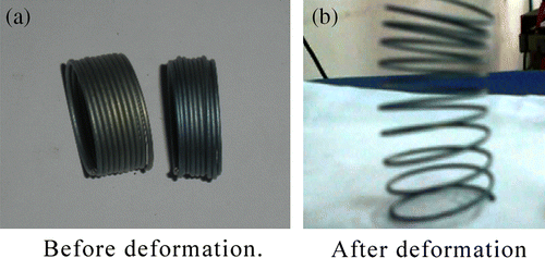
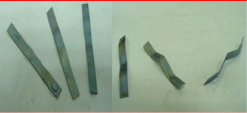
Figure shows how a SMA ribbon provides the force and deformation to separate the parts and components joined by a snap-fit connection. So, at the design stage, the key is to satisfy the requirements of force and deformation.
Figure 2 SMA ribbon before and after deformation.
Active disassembly devices such as SMP snap fasteners, screws or rivets need to be triggered in the appropriate temperature field. Their strength will reduce by several orders of magnitude near the trigger temperature, when they can be broken and separated by the force and deformation provided by the SMA driving part (such as SMA coil springs, ribbons or tubes) when triggered. The failure mode is usually by breakage of the active disassembly devices.
5 Typical active disassembly device based on the decapitated head method
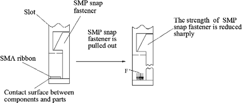
Active disassembly devices based on the decapitated head method mainly include SMP snap fasteners, screws or rivets. One type of active disassembly device is the SMP snap fastener that has high joint strength, so it is always used in those connecting parts that demand high joint strength or require a special function. Because the strength of the snap fastener reduces sharply near the trigger temperature, a vertical driving force can be used to make the connection between the snap fastener and slot fail. A SMP snap fastener can be pulled out by a very low driving force, because it has very low strength near the trigger temperature. Active disassembly driving parts, such as SMA coil springs or SMA ribbons, are usually put in the direction that the SMP snap fastener will be pulled out (normally vertical), as shown in Figures and .
Figure 3 SMP snap fastener is softened and pulled out by the SMA coil spring.
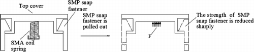
Figure 4 SMP snap fastener is softened and pulled out by the SMA ribbon.
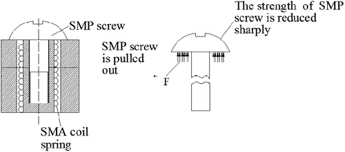
Another type of active disassembly device is the SMP screw. It does not have high joint strength, but the device is simple. It is usually used in those connecting parts that do not demand high joint strength. The heat is transferred to the threaded portion of the screw through the inside wall of other parts, while the terminal is directly heated. As a result, the screw is heated unevenly and it can be pulled out. No matter which part softens first, the pulled out area is usually that which has the lowest strength. When the strength reduces sharply near the trigger temperature, the screw experiences a certain strength gradient because of being heated unequally. The driving force can be provided by either a SMA ribbon or SMA coil spring. The SMA ribbon can be placed at the contact surface of parts, as shown in Figure . The SMA coil spring can be placed between parts, as shown in Figures and . When heated to the trigger temperature, the SMA coil spring or SMA ribbon offers the driving force to make the connection fail.
Figure 5 SMP screw is pulled out and broken by the SMA ribbon.
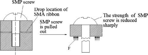
Figure 6 SMP screw is softened and pulled out by the SMA coil spring.
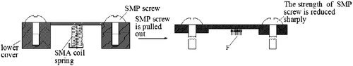
Figure 7 SMP screw is softened and pulled out by the SMA coil spring.
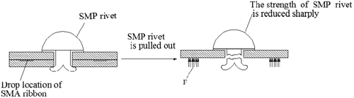
The SMP rivet is also a kind of active disassembly device. A strength gradient will be generated due to unequal heating between the terminals and the working segment. The driving force usually causes breakage where the strength is at its lowest. When heated, the sides of the rivet usually soften first, and then it can be pulled out directly by the driving force. The SMP rivet based on the decapitated head method can be automatically assembled. A SMA ribbon is placed at the contact surface of parts to provide the driving force when triggered to pull out the rivet, as shown in Figure .
Figure 8 SMP rivet is softened and pulled out.
6 The design method for a typical active disassembly device based on the decapitated head method
6.1 Design criteria for an active disassembly device based on the decapitated head method
| 1. | The strength of an active disassembly device must match the connection strength requirements of parts and components. | ||||
| 2. | The trigger temperature must be higher than the normal operating temperature of the product. Generally the trigger temperature should be 20°C above the normal operating temperature to avoid reducing the strength of device and decreasing the reliability of products under normal use. | ||||
| 3. | The SMA driving parts should be placed as close as possible to the active disassembly device and they should be arranged uniformly on both sides so that the device can be stressed evenly. | ||||
| 4. | The trigger temperature for the SMA driving part must be 5–10°C higher than that of the active disassembly device, to ensure that the SMA driving part is excited after the strength of the device has reduced. | ||||
| 5. | The active disassembly device and the SMA driving parts should be placed at, or as near as possible to, the outside of the housing in order to ensure that the device can be heated evenly and thus shorten the trigger time. | ||||
6.2 The design method for an active disassembly device based on the decapitated head method
(1) Choose an appropriate material for the active disassembly device. For small-lot products which have high connecting strength requirements and complex structure, ordinary plastics such as polyvinyl chloride (PVC), polystyrene (PP) and polyurethane (PE) can be chosen as the SMP material after physical cross-linking irradiation processing. They are inexpensive. For those products that are produced in large numbers, and that do not have high connection strength requirements, shape memory polyurethane (SMPU), styrene/butadiene copolymers and other SMMs can be chosen, but the machining processes are complex and the cost is high.
(2) Calculate the detailed dimensions of the active disassembly device according to the connecting strength requirements. For a SMP screw or rivet, the strength requirement mainly consists of tensile strength and shear strength. For a SMP snap fastener, the requirements mainly consist of restraint, compatibility, sturdiness, strength, etc. (Bonenberger Citation2004).
The device strength is the only factor when a SMP snap fastener is designed. The cross-sectional area of a snap fastener is given by
(3) Choose a reasonable driving part. When the parts and components are bulky but the structure is simple, a SMA coil spring can be used because there is enough space, otherwise a SMA ribbon will be chosen.
(4) According to the strength after the active disassembly device has softened, the lowest tensile force required to pull out the SMP snap fastener, screw or rivet near the trigger temperature can be calculated. Then the dimensions of the SMA driving part can be calculated according to the lowest tensile force requirement. Finite-element analysis software can also be used to simulate this step.
The length of SMA ribbon must be determined from , and the driving force of the SMA ribbon from
For example, the trigger temperature for a SMPU screw is 65°C, and that of Ni–Ti alloy coil spring driving part is 70°C. The maximum tension force that the SMPU screw can bear is 20 N, and the maximum shear force is 5 N. The chosen safety factor is 1.5; the tensile strength is 27 MPa and the shear strength is 11.5 MPa. The diameter of screw required can be calculated as follows:
Rounding up, a screw diameter of 2 mm is chosen. When the screw is used normally, the maximum tension force that the screw can bear is 84.8 N. The tensile strength of the SMPU screw after it has been triggered reduces to 3 MPa, and the maximum tension force that the SMPU screw can bear is 9.4 N. According to the driving force requirements of Ni–Ti alloy and the material property parameters when triggered, the diameter of the SMA coil spring can be calculated (Li Citation2008).
It is assumed that a SMPU snap fastener, whose trigger temperature is 65°C, is chosen for the connecting part. At ambient temperature it is in plastic state. The maximum tension force it can bear is 50 N, and the maximum shear force is 15 N. The modulus of elasticity is 666 MPa, the tensile strength is 27 MPa, the shear strength is 11.5 MPa and Poisson's ratio is 0.3. At the trigger temperature it is in a rubbery state, the modulus of elasticity is 7.8 MPa, and the tensile strength is 3 MPa. The cross sectional area of a snap fastener can be calculated according to the strength requirements:
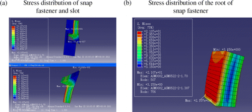
Rounding up, 3.2 mm2 is chosen as the cross sectional area of the snap fastener. A Ni–Ti coil spring is used as the driving part. With the help of ABAQUS finite-element analysis software, we know that the requisite driving force is about 11 N. The minimum stress of the root is 3.15 MPa, which is greater than the tensile strength in the rubbery state, so the root of the snap fastener is pulled out, as shown in Figure . So the detailed dimensions of the SMA coil spring can be calculated. The maximum shear stress of the Ni–Ti coil spring is 120 MPa, the modulus of shear G is 8000 MPa, is 11 N and distortion S is 20 mm.
Figure 9 Stress distribution when SMPU snap fastener is pulled out: (a) Stress distribution of snap fastener and slot; (b) Stress distribution of the root of snap fastener.
Supposing D = 12 mm and d = 1.5 mm, so
So, d = 1.5 mm satisfies the requirements.
So, the diameter of SMA coil spring designed is 12 mm, the wire diameter is 1.5 mm and the number of circles is 5 (Li Citation2008).
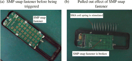
A remote controller was considered as an example. The SMA coil spring, for which the trigger temperature is 75°C, was placed between the circuit board and back cover. The circuit board was fixed by four SMP snap fasteners, whose trigger temperature is 70°C. When heated to about 70°C using a heat gun, the SMP snap fasteners began to soften and they were pulled out by the driving force provided by the SMA coil spring. The circuit board and back cover were dismantled and separated automatically, as shown in Figure .
Figure 10 SMP snap fastener is pulled out by the SMA coil spring: (a) SMP snap fastener before being triggered; (b) pulled out effect of SMP snap fastener.
7 Case analysis
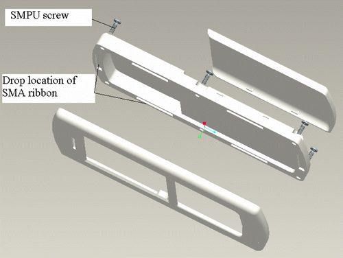
For this case study, the traditional connections for a cell phone were changed by adopting the active disassembly technology based on the decapitated head method. Six SMPU screws were used as the connecting parts of the housing. At normal temperature, the maximum tensile force each SMPU screw can bear is 15 N, and the maximum shear force is 10 N. The tensile strength is 27 MPa, and the shear strength is 11.5 MPa. According to the strength requirement, the calculated result of the diameter of these screws is about 2 mm. The trigger temperature of SMPU screws is 65°C. Near the trigger temperature, these screws are in the rubbery state. Their modulus of elasticity is 7.8 MPa, Poisson's ratio is 0.3 and the tensile strength is 3 MPa. Six SMA ribbons, whose trigger temperature is 70°C, are uniformly arranged on both sides of the screws, as shown in Figure .
Figure 11 Separated cell-phone model.
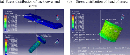
With the help of ABAQUS, the force analysis of the SMPU screws near their trigger temperature was simulated. Using the simulated results, the dimensions of the SMA ribbons could be calculated. The material of the housing is acrylonitrile butadiene styrene (ABS) which has a modulus of elasticity of 2000 MPa and Poisson's ratio of 0.3. Because of the symmetrical structure, only one half of the back cover model required analysis. The bottom of the screws is fixed and the symmetry surface has the constraint of symmetrical boundary. When triggered, the SMA ribbon provides the driving force and the deformation acting on the back cover to tension the screws. The driving force acts on the position where the SMA ribbon is placed, as shown in Figure . By conducting several load tests, the calculated driving force was about 7 N, and the minimum stress of the head of the screw was 3.56 MPa, which is greater than the tensile strength of the SMPU screws, so the head of the screw will be pulled out, as shown in Figure .
Figure 12 The force model of the back cover.
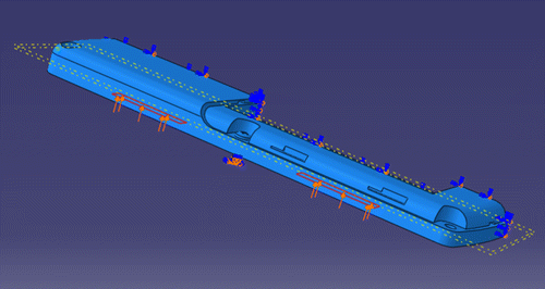
Figure 13 Stress distribution of back cover and screw: (a) Stress distribution of back cover and screw; (b) Stress distribution of the head of screw.
The SMA ribbon is made of Ni–Ti alloy, which can provide the 7 N driving force. The distortion is 2 mm, and the wave number is 3. The maximum shape memory strain is 6% and the maximum restoring stress is 400 MPa. The detailed dimensions of the SMA ribbon can be calculated from
If the number of waves is 2, the length L is 50 mm and the force F is 7 N,
The design method for a SMP rivet based on the decapitated head method is similar to that mentioned above. The SMP snap fastener, screw and rivet based on the decapitated head method do not require two moulding steps, and these active disassembly devices made by injection or pouring only need to satisfy the joint strength requirement. The SMP snap fastener, screw and rivet can be pulled out near the trigger temperature to make the connecting relationship fail and achieve active disassembly. The detailed dimensions of SMA driving parts can be calculated by finite-element analysis. The analytical result can be used as a theoretical reference when products are designed with the active disassembly device based on the decapitated head method.
8 Conclusions
The design method and criteria for an active disassembly device based on the decapitated head method have been presented based on the typical connections of active disassembly parts and components. The method and criteria were based on an analysis of the strength of SMP materials at, or near, the trigger temperature for active disassembly. The validity of the method and criteria were demonstrated using a case study.
| 1. | The theory of active disassembly based on the decapitated head method in its typical forms has been presented. This can be used as a guiding reference for the arrangement of SMA driving parts. Near the trigger temperature, the strength of an active disassembly device made from SMP reduces sharply by several orders of magnitude. This phenomenon can be used to break a connecting device with the help of the force provided by driving parts made from SMA materials, thus promoting damage-free active disassembly and the recovery of parts and/or components. | ||||
| 2. | The design method and criteria for an active disassembly device based on the decapitated head method have been provided, and a foundation for the application of this method to the improvement of products has been presented. When products are designed, the design method and criteria of an active disassembly device based on the decapitated head method can be applied to optimise the detachable device, and to redesign the products, so as to achieve the effective recovery of products at the end of their lives and to raise the ratio of parts and components which can be disassembled and recycled. | ||||
| 3. | Utilising a case study, the processes and steps for the application of the decapitated head method to products were presented. The structure of a traditional cell-phone was improved by using this design method and principle. The case study provides the industrial foundation for the method, which can be used to guide the design of other products. | ||||
| 4. | Further research is required to promote active disassembly devices and the design method for products incorporating such devices. In particular, there is a need to research the reliability of active disassembly products and active disassembly devices triggered by two or more media. In this respect the disconnection of parts and components triggered simultaneously or sequentially will be investigated. | ||||
Acknowledgements
The research presented in this paper was financially supported by a National Natural Science Foundation Project (Reference: 50775064).
References
- Bonenberger , P.R. 2004 . “ The First snap-fit handbook: creating attachments for plastic parts ” . In Translate , Edited by: Feng , L. , Ma , X. and Dong , L. Vol. 6 , 13 – 22 . Beijing : Chemical Industry Press .
- Chiodo, J.D., Billett, E.H., and Harrison, D.J., 1999a. Active disassembly using shape memory polymers for the mobile phone industry. Proceedings of the 1999 IEEE international symposium on electronics and the environment, 11–13 May, Danvers, MA. Piscataway, NJ: IEEE, 151–156
- Chiodo , J.D. , Billett , E.H. and Harrison , D.J. 1999b . “ An initial investigation into active disassembly using shape memory polymers ” . In In: Proceedings of the first international symposium on environmentally conscious design and inverse manufacturing , 590 – 596 . Tokyo, Japan. Piscataway, NJ : IEEE . 1–3 February
- Li, X., 2008. Research of active disassembly devices' design theory and methods based on smart materials. Thesis (MSc), Hefei University of Technology, Heifei, China
- Yu , H. , Feng , X. and Li , G. 2009 . Connection parts design example of pure solution , Beijing : Mechanic Industry Press .