Abstract
The diminishing resources and continuously increasing cost of petroleum in association with their alarming pollution levels from diesel engines have caused an interest in finding alternative fuels to diesel which are renewable and sustainable. Emission control and engine efficiency are two most important parameters in current engine design. The impending introduction of emission standards such as Euro IV and Euro V is forcing the research towards developing new technologies for combating engine emissions. The classification of Euro IV and V norms is applicable to heavy-duty engines in Europe, where as Euro 5 is applicable to light-duty engines. This paper presents the effects of exhaust gas recirculation (EGR), swirl augmentation techniques and ethanol addition on the combustion of Honge oil methyl ester (HOME) and its blends with ethanol in a diesel engine. From the experimental work conducted, it is found that the combustion of HOME plus up to 15% ethanol blend in a diesel engine operated with optimised parameters of injection timing 23° Before Top Dead Centre and compression ratio 17.5 results in acceptable combustion emissions and improved brake thermal efficiency (BTE). The addition of ethanol increased BTE with reduced hydrocarbons (HCs), CO and smoke emissions. However, NO x emissions increased dramatically. Use of appropriate EGR reduces NO x to acceptable levels. The implementation of swirl augmentation techniques further resulted in increased BTE and considerable reduction in tail pipe emissions such as smoke, HCs, CO and NO x . The effect of swirl by providing grooves on the piston was taken into consideration to find the overall biodiesel engine performance, which gives scope for further studies.
1. Introduction
The demand for petroleum fuel will rise steeply with every passing decade and is expected to reach nearly 250 million metric tonnes by the year 2024 (Barnwal and Sharma Citation2005, Agarwal Citation2006, Yage et al. Citation2009). A large amount of energy is needed to sustain industrial growth and agricultural production. The diminishing and continuously increasing cost of petroleum resources associated with their alarming pollution levels from diesel engines has created an interest in finding a suitable alternative and renewable fuel to diesel. The use of such alternative fuels in diesel engines will ensure energy security of many developing countries such as India and will simultaneously address environmental concerns. India imports 83% of its total crude oil requirement. Biodiesel is one of the best substitutes for petroleum fuels because it is environmentally benign, sustainable and economically suitable for agricultural countries (Raheman and Phadatare Citation2004). Biodiesel derived from Honge non-edible oil is found to be particularly suitable as it is locally and abundantly available (Banapurmath et al. Citation2008, Citation2009, Murugesan et al. Citation2009).
Ethanol is a renewable energy source and can be made from many raw materials such as sugar cane, molasses, waste biomass materials, corn and sugar beets by using already improved and demonstrated technologies (Xingcai et al. Citation2004, Banapurmath and Tewari Citation2010, Lei et al. Citation2011). By increasing ethanol in biodiesel–ethanol blends, cold flow characteristics of the blends will improve with decreased specific gravity and viscosity. Adding ethanol to Honge oil methyl ester (HOME) improves the efficiency of dual fuel engines as it lowers the viscosity of the blends and further increases the mixture volatility (Banapurmath and Tewari Citation2010). Biodiesel and ethanol are therefore more popular contenders as alternative fuels to diesel.
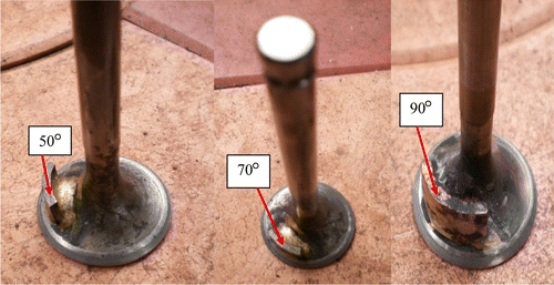
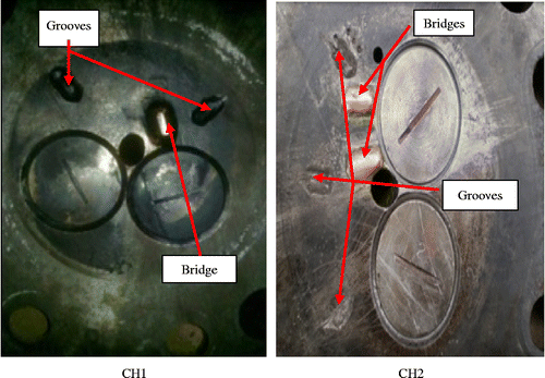
Swirl augmentation techniques result in better combustion with increased brake thermal efficiency (BTE) and reduced emissions. In addition, swirl augmentation leads to decreased carbon deposits, fuel consumption, exhaust gas temperature and tendency to knock (Parker and Walker Citation1972, Timotey Citation1985, Van Gerpen et al. Citation1985, Heywood Citation1988, Rao et al. Citation1993, Kang and Reitz Citation1999, Benajes et al. Citation2004, Bonatesta et al. Citation2007). Swirling is created by providing grooves on the bowl-shaped cavity on the piston and manifold designs (Prasad et al. Citation2011). The effect of initial swirl can be the solution for overcoming the power loss in a dual fuel engine and prevention of knock. Reduced NO x is observed as a result of increased heat loss to the wall and reduced temperature with introduction of swirl. Swirl also influences the ignition delay by exchanging the portion between physical and chemical ignition delay. In order to achieve different swirl intensities inside the cylinder, two design parameters were changed: the cylinder head (CH) and the inlet valve masking. This intensification of the swirl is done by cutting grooves and adding bridges on the CH. Two different configurations of the CH were considered for this study: one includes two grooves and one bridge, and the other three grooves and two bridges. The inlet valve masking with angle of mask 50°, 70° and 90° was provided on the inlet valve for this study.
Different methods of NO x reduction have been used and reported in the literature, which include retarded injection timing, lowered intake temperature, water injection emulsified in the fuel, exhaust gas recirculation (EGR) and lowered compression ratio (Gros Citation1991, Pierpont et al. Citation1995, Ladommatos et al. Citation1998, Yoshimoto and Tamoki Citation2001, Abd Alla Citation2002, Tomazic and Pfeifer Citation2002, Agarwal et al. Citation2004, Citation2006, Srinivasan et al. Citation2006, Peng et al. Citation2008). These methods reduce NO x emissions but increase particulate emissions at higher engine loads. Hence, there is a trade-off between NO x and smoke emissions. Therefore, it is essential to use particulate trap to reduce the amount of unburnt particulates in EGR. The objective of this work involves studying the effects of EGR, swirl augmentation techniques and ethanol addition to biodiesel in the modified diesel engine. Comparison of performance, emission and combustion characteristics of the biodiesel-fueled engine with EGR, swirl augmentation techniques and ethanol addition effects is presented.
2. Characterisation of fuels used
Honge oil being a non-edible oil with viscosity nearly 16 times more than diesel was suitably converted into its methyl ester using the transesterification process.
2.1 Transesterification of Honge oil and fuel properties
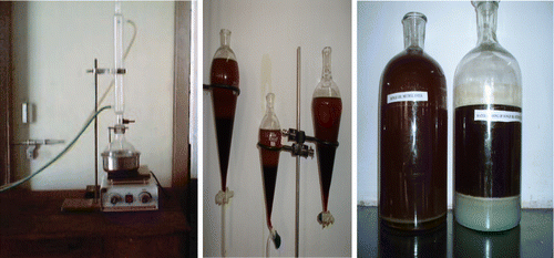
The set-up for transesterification process is shown in Figure with the upper layer showing HOME and the lower layer showing glycerol. Figure also shows the water washing of HOME and the subsequent moisture removal from ester using silica gel crystals. Initially, parameters such as temperature, molar ratio and catalytic concentration affecting the transesterification of Honge oil were optimised. The transesterification set-up consists of a 2-l capacity, round-bottomed flask provided with three necks, which was placed in a water container for heating the oil. A high-speed motor with a magnetic stirrer was used for vigorous mixing of the oil. In the transesterification process, triglycerides of Honge oil react with methyl alcohol in the presence of a catalyst (NOH/KOH) to produce a fatty acid ester and glycerol. In this process, 1000 g Honge oil, 230 g methanol (MERC brand) and 8 g sodium hydroxide pellets were placed in a round-bottomed flask. The contents were heated to 70°C and stirred vigorously for 1 h to promote ester formation. The mixture was next transferred to a separating funnel and allowed to settle under gravity overnight. The upper layer in the separating funnel consists of home methyl ester whereas the lower layer consists of glycerol that was removed. The separated ester was mixed with 250 g hot water and allowed to settle under gravity for 24 h. Water washing separates residual fatty acids and catalyst, and were removed by using a separating funnel. Finally, silica gel crystals were added to remove the moisture from the ester (Banapurmath et al. Citation2008).
The properties of Honge oil and its biodiesel (HOME) are provided in Table .
Table 1 Property of diesel, Honge and HOME, and blends of HOME with ethanol.
2.2 Use of ethanol in diesel engines
Ethanol has a much lower flash point than diesel and requires greater precautions while preparing its blends with biodiesels (Hansen et al. Citation1989). Anhydrous ethanol is highly hygroscopic and is practically impossible to stay as such in diesel under a wide range of conditions. At lower temperatures, the miscibility is limited. Additives or emulsifiers, co-solvent or iso-propane must be used to ensure its solubility in diesel fuel. Anhydrous ethanol (200 proof) does not require an emulsifying agent and lower proof ethanol requires an emulsifying agent to form the opaque macro-emulsion. This could separate into its two phases if allowed to stagnate for a long period (Noguchi et al. Citation1996, Corkwell et al. Citation2003, Jeuland et al. Citation2004, Park et al. Citation2008, Zhu et al. Citation2011). In view of engine durability, blends up to 15% (by vol.) ethanol in diesel/biodiesel fuel can be considered relatively safe for diesel engine applications. Adding ethanol to diesel fuel can reduce its lubricity and create potential wear problems in fuel pumps (Banapurmath and Tewari Citation2010).
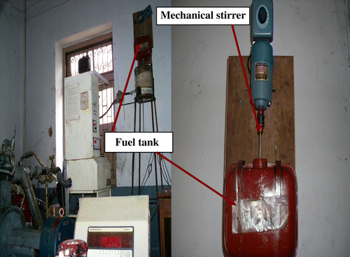
In this study, HOME was further blended with ethanol in different proportions of 7.7% and 15%, and the resulting blend properties are shown in Table . A stirrer was mounted inside the fuel tank to prevent phase separation, and the mixture was supplied instantaneously to the engine. Figure shows the mechanical stirrer used to mix the biodiesel–ethanol blend mixtures. At and beyond 20% ethanol blend in biodiesel, the results were not encouraging, since a clear separation was observed between the biodiesel and the ethanol layers. At present, only 7.7% ethanol blend has been successfully adopted in the state road transport sector. However, use of higher ethanol blend ratio needs further investigation.
Table 2 Composition of Honge oil (Shirsath et al. Citation2012).
3. Experimental set-up
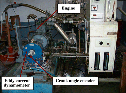
The experimental investigations were carried out on a single cylinder four-stroke Compression Ignition (CI) engine test rig operated on biodiesel and blends of biodiesel and ethanol. The effects of EGR and swirl augmentation techniques on the performance of the engine fueled with the above fuel combinations were studied. Figures and show the arrangement of fuel blending and overall view of the test rig modified to operate on biodiesel–ethanol blended fuels. The specifications of the engine are given in Table . The engine was always operated at a rated speed of 1500 rpm. A piezoelectric pressure transducer was mounted on the CH surface to measure the cylinder pressure for combustion study. The engine tests were conducted with HOME–ethanol blends at different load conditions. The injection timing was kept fixed at 23° Before Top Dead Centre (BTDC), and the compression ratio was maintained at 17.5. Masking was provided on the inlet valve with angle of mask varying from 50°, 70° and 90°, respectively, as shown in Figure . In addition to the inlet valve masking, the CHs were also suitably provided with different grooves and bridges to study the effect of swirl augmentation techniques on engine performance. In one CH denoted as CH1, one bridge and two grooves were provided, whereas in another denoted as CH2 two bridges and three grooves were provided accordingly as shown in Figure . Tables and show the specifications of exhaust gas analyser and the smoke meter used for the emission measurements with measurement accuracies and uncertainties reported. The emissions of hydrocarbons (HCs) and NO x are measured in ppm whereas those of CO and CO2 were measured in percentage. The smoke is measured in Hartridge Smoke Units (HSU).
Table 3 Specification of the engine.
Table 4 Specifications of exhaust gas analyser.
Table 5 Specifications of smoke meter.
EGR arrangement was suitably designed and fabricated and was provided to the engine. The EGR rate was accurately calculated using the following equation:
4. Results and discussion
The results and discussion section is explained under three headings. In the first two cases, diesel engine operation with HOME and ethanol is considered with and without the induction of EGR. In the last case, use of swirl augmentation techniques on the performance of the engine with HOME operation is considered.
4.1 Performance and emission tests on biodiesel and ethanol blends without EGR: performance parameters
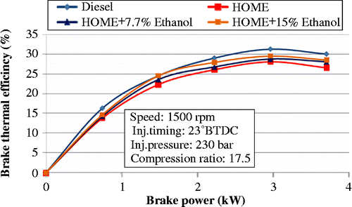
Variation in BTE with power output for HOME and HOME–ethanol blends is presented in Figure . For all the loads tested, HOME and its blends with ethanol showed inferior performance compared to diesel. The reason for poor biodiesel performance is mainly attributed to its lower calorific value, volatility and Cetane number associated with its higher viscosity. Ethanol has a lower Cetane number as well as boiling point and higher oxygen content than HOME (Table ). For the same injection pressure and injection timings, the BTE improved with ethanol–HOME blended fuels with increasing ethanol content in blends. The reason could be that the quality of the spray improved with blended fuels due to lower boiling point of ethanol than of HOME itself. The combustion is more complete in the fuel-rich zone due to the oxygen present in ethanol-blended fuels. This results in enhanced combustion efficiency and decreased heat losses in the cylinder due to lower flame temperature of ethanol-blended fuels compared to HOME. Fifteen percent ethanol–HOME blend resulted in improved performance.
4.1.1 Emission parameters
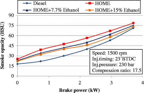
Variation in smoke opacity with power output for HOME and HOME–ethanol blends is shown in Figure . Smoke opacity is an indicator of dry soot emissions. Adding oxygenates to HOME has a remarkable effect on the reduction in smoke emissions, especially at high loads. Smoke opacity decreased with increased ethanol content in the blended fuels. Presence of bonded oxygen reduces the probability of soot nuclei formation in locally rich zones. The enrichment of oxygen content in the fuel due to the addition of oxygenates by HOME and ethanol resulted in more complete combustion. Fifteen percent ethanol–HOME blend resulted in lower smoke emissions.
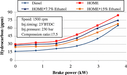
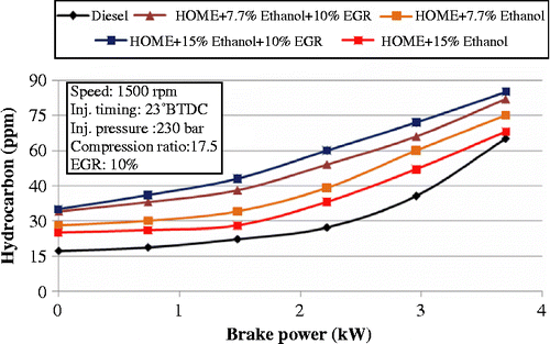
Unburned HC emissions consist of incompletely burnt fuels that represent a serious problem at light loads in diesel engines. Figure shows the variation in HC emission with power output for HOME and HOME–ethanol blends. HC emissions were reduced with HOME–ethanol blends because of their improved combustion. Ethanol added to the HOME provides more oxygen for the combustion process and leads to improved combustion. In addition, ethanol molecules are polar, which cannot be absorbed easily by the non-polar molecule lubrication oil layer, and therefore, ethanol can lower the possibility of production of HC emissions. HC emission is lower for 15% ethanol–HOME blend.
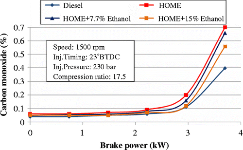
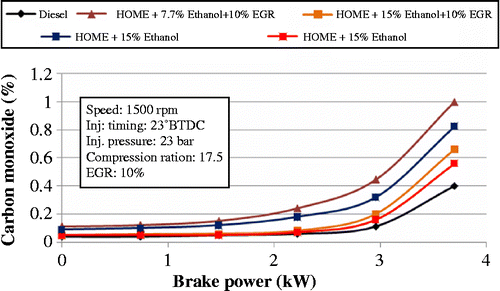
Emissions of CO are greatly dependent on the air–fuel ratio relative to stoichiometric proportions. Rich combustion invariably produces CO emissions and increases linearly with the deviation from the stoichiometry. Figure shows variation in CO emission with power output for HOME and HOME–ethanol blends. For ethanol–HOME blends, the CO emission reduced due to oxygen content in ethanol. CO emission was lower for ethanol 15% blend.
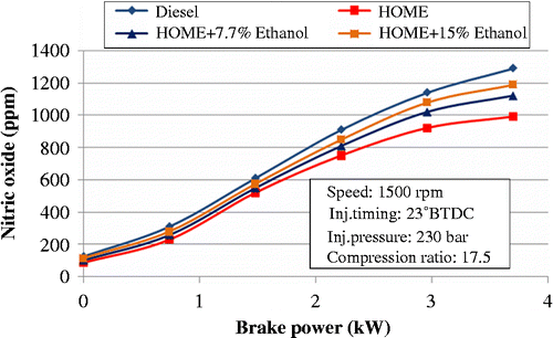
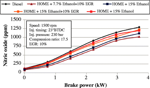
Figure shows variation in NO x emission with power output for HOME and HOME–ethanol blends. The NO x emission behaviour for all the fuels was found to be similar at lower load with a slight increase in its magnitude at higher load. This is because at lower load, the adiabatic flame temperature of stoichiometric air–ethanol flame is slightly lower. However, the lower Cetane number of ethanol leads to an increase in the ignition delay and the greater rates of pressure rise resulting in higher peak pressure and combustion temperatures. Ethanol blending in biodiesel has little influence on NO x emission (Ren et al. Citation2008, Shudo et al. Citation2009). The exhaust gas temperature increases with increasing ethanol ratio in the fuel mixture. This high peak temperature increases NO x emissions. Hence, as ethanol concentration increases, NO x emissions also increase. Also ethanol and ester being the oxygenated fuel combinations result in higher NO x emissions due to more complete combustion than the ester considered alone. At lower loads, the BTE reduces with relatively lower combustion temperatures inside the engine cylinder when compared with higher load operation. The incomplete combustion leading to reduced premixed combustion could also be the reason for this behaviour.
4.2 Performance and emission tests on biodiesel and ethanol blends with EGR
4.2.1 Performance parameters
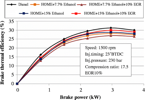
Figure shows the effect of power on BTE levels for HOME and HOME–ethanol blends. It can be seen that, with 10% EGR induction, BTE reduced with an increase in power output. This is because deterioration in combustion occurs when 10% EGR is introduced and the gaseous fuel–air mixture becomes diluted with exhaust gas. The introduction of 10% EGR reduces the rates of auto ignition reactions, as indicated by an increase in the ignition delay period. The premixed combustion fraction increases and causes a delay in the whole diffusive combustion event with 10% EGR, because a larger amount of fuel is injected during the longer ignition delay period. Deterioration in the air–fuel mixture reduces the oxygen concentration leading to incomplete combustion. Although the presence of oxygen in vegetable oils compensates for oxygen deficiency, their lower calorific value and higher density leads to reduced BTE.
4.2.2 Emission parameters
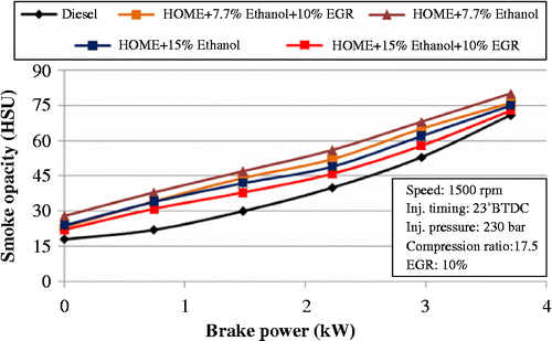
The effect of brake power on smoke opacity for standard diesel operation and HOME and HOME–ethanol blends is shown in Figure . It was observed that smoke emission was higher for the HOME and HOME–ethanol blends than for standard diesel operation. This may be due to the presence of heavier molecular structure, higher viscosity and higher free fatty acids with HOME. Ethanol-blended HOME results in lower smoke emissions. The smoke opacity for HOME and HOME–ethanol blends was even higher with 10% EGR induction. This negative effect of EGR on smoke opacity could be due to the reduction in the engine air–fuel ratio.
The effect of brake power on HC emission is shown in Figure , and it can be observed that HC emissions are comparatively higher for HOME and HOME–ethanol blends. With the 10% EGR induction, the combustion degradation lowers the temperature. The decreased air–fuel ratio associated with EGR induction and reduced combustion temperature results in incomplete fuel combustion. These factors may lead to the higher HC emissions.
Figure shows the effect of brake power on CO emissions. CO is comparatively low for standard engine operation with diesel. For HOME and HOME–ethanol blends, 10% EGR induction dilutes the combusting mixture. Therefore, insufficient oxygen is available for better combustion, and the lower combustion temperature prevailing in the engine cylinder leads to comparatively higher CO emissions.
Figure shows the effect of brake power on NO x emissions. The lowest values were obtained with HOME and HOME–ethanol blends with 10% EGR induction. EGR appears to reduce the adiabatic flame temperature and, thereby, the combustion temperature and hence NO x emissions were reduced. Therefore, NO x concentration decreases as CI engine inlet airflow is diluted at a constant fuelling rate.
4.3 Effect of swirl
Swirl effect on the performance of HOME-fueled diesel engine is discussed in this section. The values presented refer to full load engine operation at 3.7 kW. The study on the effect of swirl on the engine performance is divided into two main headings. The first presents the results obtained on the engine performance considering the effect of swirl introduced by the inlet valve masking alone and the second involves use of both inlet valve masking and grooves provided on the CHs.
4.3.1 Effect of swirl using inlet valve masking
4.3.1.1 Brake thermal efficiency
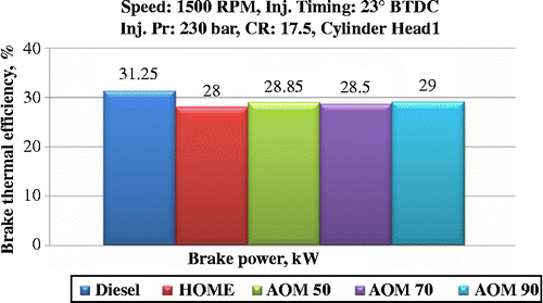
Figure shows variation in BTE with angle of masking for HOME operation. As the angle of masking increases, the BTE increased considerably with HOME till 90°. The reason for this increase in BTE is due to better mixing of the fuel combinations inside the engine cylinder. For 120° angle of mask, there was no improvement noticed in engine performance as well in engine emissions due to drop in volumetric efficiency and incomplete combustion. Hence, the results obtained with 120° angle of masking are not reported in this study.
4.3.1.2 Smoke emission
Figure shows variation in smoke emission levels with angle of mask for HOME. As the angle of mask increases, the smoke emission levels decreases considerably with the HOME till 90° angle of mask. This could be due to swirl; it helps to achieve better mixing of air and HOME and results into better combustion. Therefore, swirl improves the combustion of fuel by considerably reducing smoke emissions.
4.3.1.3 HC emission
Figure shows variation in HC emissions with angle of mask for HOME. As the angle of mask increased, the HC emission levels decreased considerably with the HOME operation. From the figure, it follows that reduction in HC emissions was due to better combustion with higher heat release as it is affected by the swirl induced.
4.3.1.4 NO x emission
Figure shows variation in NO x emission levels with angle of mask for HOME. From the figure, it follows that as the angle of mask increases, the NO x decreases considerably with the HOME operation. Increasing the initial swirl reduces the in-cylinder temperature which in turn reduces thermal NO x .
4.3.2 Effect of swirl using combination of inlet valve masking and CH grooves on the CH
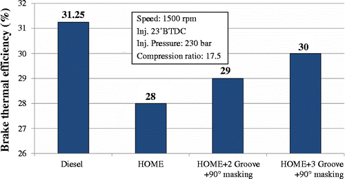
From Figure it is observed that BTE increases with swirl. A shorter combustion period is generally observed with swirl compared to normal engine without swirl effect. This may also be due to higher heat release during the early stage of combustion. BTE further increases with three groove 90° mask CH.
4.3.2.1 Emissions
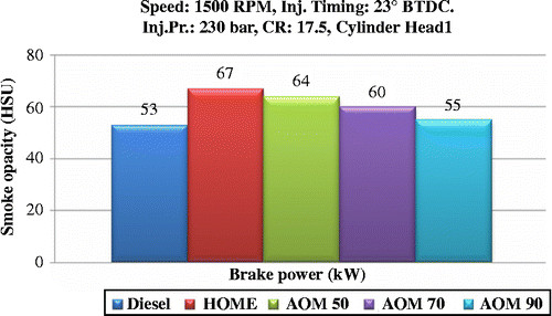
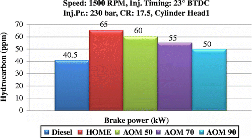
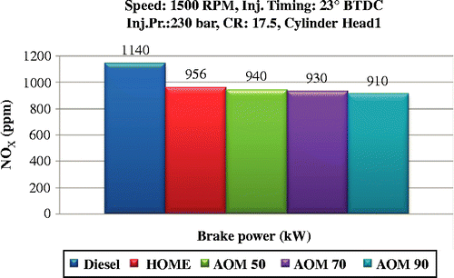
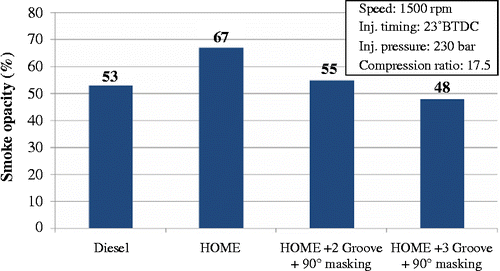
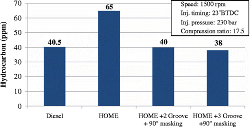
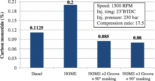
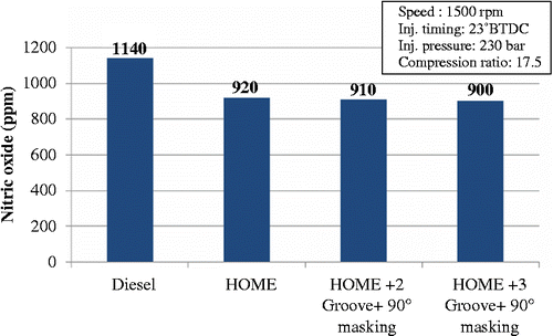
From Figure it follows that swirl improves the combustion, reducing the smoke considerably. The smoke further decreases with CH2. From Figures and it follows that swirl improves the combustion process reducing HC and CO emissions considerably. The HC and CO further decrease with CH2. Compared to CH1, CH2 resulted in overall better performance with increased BTE and reduced emissions. From Figure it follows that the effect of swirl increases NO x when compared to normal engine (without swirl) with three grooves 90° mask CH.
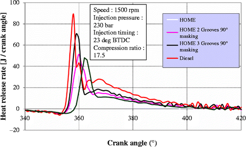
Figure shows the heat release rate with different swirl augmentations used. Swirl shows significant influence on the combustion process. As the swirl increases, the rate of heat release becomes faster, enhancing the fuel–air mixing process, which makes faster distribution of fuel accelerating plane propagation. Higher swirl reduces fuel penetration. The heat release rate increases with CH1 compared with CH2. The slow combustion rate is considered to be the main reason for low heat release rate inside CH1.
5. Conclusion
Exhaust emissions and combustion characteristics of a diesel engine operated with HOME were carefully examined to study the different effects of fuel modification, EGR and swirl on the engine performance. From this study, the following conclusions were made:
| 1. | Use of ethanol in diesel engines is still a critical issue. As the percentage of ethanol in biodiesel blend increases beyond 15%, a phase separation is observed. | ||||
| 2. | The performance of HOME–15% ethanol blends resulted in better performance. However, NOx emissions increased. | ||||
| 3. | The NOx emissions were significantly reduced by 28% with 10% EGR induction. The overall performance with 10% EGR was poor due to increased smoke, HC and CO emissions. | ||||
| 4. | It was observed that swirl arrangement provided in the combustion chamber further improved the overall performance of the engine fueled with HOME. Inlet valve masking along with grooves and bridges provided on the CH1 and CH2 could be the reason for the smoke and particulate emissions of the biodiesel fueled engine. | ||||
References
- Abd Alla , G.H. 2002 . Using exhaust gas recirculation in internal combustion engines: a review . Journal on Energy Conservation and Management , 43 : 1027 – 1042 .
- Agarwal , A.K. 2006 . Biofuels (alcohols and biodiesel) applications as fuels for internal combustion engines . Progress in Energy and Combustion Science , 33 : 233 – 271 .
- Agarwal , A.K. 2004 . Effect of EGR on the exhaust gas temperature and exhaust opacity in CI engine . Sadhana , 29 ( 3 ) : 275 – 284 .
- Agarwal, D., Agarwal, A.K., and Sinha, S., 2006. Experimental investigation of control of NOx emissions in biodiesel fuelled compression ignition engine. Renewable Energy, 31 (14), 2356–2369
- Banapurmath , N.R. and Tewari , P.G. 2010 . Performance combustion and emissions characteristics of a single cylinder compression ignition engine operated on ethanol–biodiesel blended fuels . Proceedings of the Institution of Mechanical Engineers, Part A: Journal of Power and Energy , 224 : 533 – 543 .
- Banapurmath , N.R. , Tewari , P.G. and Hosmath , R.S. 2008 . Combustion and emission characteristics of a direct injection, compression-ignition operated on Honge oil, HOME and blends of HOME and diesel . International Journal of Sustainable Engineering , 1 ( 2 ) : 80 – 93 .
- Banapurmath , N.R. , Tewari , P.G. and Hosmath , R.S. 2009 . Effect of biodiesel derived from Honge oil and its blends with diesel when directly injected at different injection pressures and injection timings in single-cylinder water-cooled compression ignition engine . Proceedings of the Institution of Mechanical Engineers, Part A: Journal of Power and Energy , 223 : 31 – 40 .
- Barnwal , B.K. and Sharma , M.P. 2005 . Prospects of biodiesel production from vegetable oils in India . Renewable and Sustainable Energy Reviews , 9 : 363 – 378 .
- Benajes , J. 2004 . The effect of swirl on combustion and exhaust emissions in heavy-duty diesel engines . Proceedings of the Institution of Mechanical Engineers, Part D: Journal of Automobile Engineering , 218 ( 10 ) : 1141 – 1148 .
- Bonatesta , F. 2007 . “ The influence of swirl ratio on soot quantity and distribution in the cylinder of a diesel engine ” . In Proceedings of the third European combustion meeting (ECM) 1 – 6 .
- Corkwell, K.C., Jackson, M.M., and Daly, D.T., 2003. Review of exhaust emissions of compression ignition engines operating on E diesel fuel blends. SAE paper no. 2003-01-3283
- Gros , S. 1991 . Low emissions for ship machinery . The Motor Ship, Special Supplement , : 16 – 19 .
- Hansen , A.C. 1989 . Heat release in the compression-ignition combustion of ethanol . Transactions of the ASAE , 32 ( 5 ) : 1507 – 1511 .
- Heywood , J.B. 1988 . Internal combustion engine fundamentals , New York : McGraw Hill .
- Jeuland , N. , Montagne , X. and Gautrot , X. 2004 . Potentiality of ethanol as a fuel for dedicated engine . Oil & Gas Science and Technology – Rev. IFP , 59 ( 6 ) : 559 – 570 .
- Kang , K.Y. and Reitz , R.D. 1999 . The effect of intake valve alignment on swirl generation in a DI diesel engine . Experimental Thermal and Fluid Science , 202 : 94 – 103 .
- Ladommatos, N., et al., 1998. Effects of EGR on heat release in diesel combustion. SAE Paper No.: 980184
- Lei, J., Bi, Y., and Shen, L., 2011. Performance and emission characteristics of diesel engine fueled with ethanol–diesel blends in different altitude regions. Journal of Biomedicine and Biotechnology, 2011, 417421, Article ID417421 doi:10.1155/2011/417421
- Murugesan , A. 2009 . Bio-diesel as an alternative fuel for diesel engines – a review . Renewable and Sustainable Energy Reviews , 13 ( 3 ) : 653 – 662 .
- Noguchi , N. , Terao , H. and Sakata , C. 1996 . Performance improvement by control of flow rates and diesel injection timing on dual-fuel engine with ethanol . Bio-Resource Technology , 56 : 35 – 39 .
- Park , S.H. 2008 . Effect of temperature variation on properties of biodiesel and biodiesel–ethanol blends fuels . Oil and Gas Science and Technology – Rev. IFP , 63 ( 6 ) : 737 – 745 .
- Parker, R.F. and Walker, J.W., 1972. Exhaust emission control in medium swirl rate direct injection diesel engines. SAE Paper No.: 720755, 1972
- Peng , H. 2008 . Effects of EGR on combustion process of DI diesel engine during cold start . Frontiers of Energy and Power Engineering , 2 ( 2 ) : 202 – 210 . China
- Pierpont, D.A., Montogomery, D.T., and Reitz, R.D., 1995. Reducing particulate and NOx using multiple injections and EGR in DI diesel engine. SAE Paper No.: 950217
- Prasad , S.L.V. 2011 . The effect of air swirl in a diesel engine . African Journal of Scientific Research , 3 ( 1 ) : 204 – 212 .
- Raheman , H. and Phadatare , A.G. 2004 . Diesel engine emissions and performance from blends of karanja methyl ester and diesel . Biomass and Bioenergy , 27 : 393 – 397 .
- Rao, K.K., Winterbone, D.E., and Clough, E., 1993. Influence of swirl on high pressure injection in hydra DI diesel engine. SAE Paper No.: 930978
- Ren , Y. 2008 . Effects of the addition of ethanol and Cetane number improver on the combustion and emission characteristics of a compression ignition engine . Proceedings of the Institution of Mechanical Engineers, Part D: International Journal of Engine Research , 10 : 15 – 26 .
- Shirsath, G., et al., 2012. Blends of Karanja and Jatropha biodiesels for diesel engine applications. International Journal of Sustainable Engineering, 5 (3), 252–264
- Shudo , T. , Nakajima , T. and Hiraga , K. 2009 . Simultaneous reduction in cloud point, smoke, and NOx emissions by blending bioethanol into biodiesel fuels and exhaust gas recirculation . International Journal of Engine Research , 10 ( 1 ) : 15 – 26 .
- Srinivasan , K.K. 2006 . Effect of hot exhaust gas recirculation on the performance and emissions of an advanced injection low pilot-ignited natural gas engine . Journal of Power Sources , 154 : 223 – 231 .
- Timotey, D.J., 1985. A simple technique for predicting optimum fuel air mixing conditions in a direct injection diesel engine with swirl. SAE Paper No.: 851543
- Tomazic , D. and Pfeifer , A. 2002 . Cooled EGR – a must or an option for 2002/04 . SAE Paper: 2002-01-0962, 467–475, USA
- Van Gerpen, J.H., Huang, C., and Borman, G.L., 1985. SAE Paper No.: 850265
- Xingcai , L. 2004 . Effect of Cetane number improver on heat release rate and emissions of high speed diesel engine fuelled with ethanol diesel blend fuel . Fuel , 83 : 2013 – 2020 .
- Yage , D. , Cheung , C.S. and Huang , Z. 2009 . Experimental investigation on regulated and unregulated emissions of a diesel engine fueled with ultra-low sulfur diesel fuel blended with biodiesel from waste cooking oil . Journal of Science of the Total Environment , 407 ( 2 ) : 835 – 846 .
- Yoshimoto, Y. and Tamoki, H., 2001. Reduction of NOx and smoke emissions in a diesel engine fuelled by biodiesel emulsion combined with EGR. SAE Paper No.: 2001-01-0649, 467–475, USA
- Zhu , L. 2011 . Combustion, performance and emission characteristics of a DI diesel engine fueled with ethanol–biodiesel blends . Fuel , 90 : 1743 – 1750 .
