Abstract
This paper presents a stand-alone wind power system with battery/supercapacitor hybrid energy storage. A stand-alone wind power system mainly consists of a wind turbine, a permanent magnet synchronous generator, hybrid energy storage devices based on a vanadium redox flow battery and a supercapacitor, an AC/DC converter, two bidirectional DC/DC converters, a DC/AC converter and a variable load. Several control strategies for the stand-alone wind power system are involved such as a maximum power point tracking (MPPT) control, a vanadium redox flow battery charge/discharge control and a supercapacitor charge/discharge control. The proposed MPPT control combines a sliding mode control with an extreme search control to capture maximum wind energy. This strategy avoids the necessity of measuring wind velocity, obtaining models or parameters of the wind turbine and calculating the differentials of the power generated from the wind power system and from the speed of the generator. The battery charge/discharge control maintains a constant DC bus voltage. When the battery charging/discharging current reaches the setting threshold, the charge/discharge control of the supercapacitor is triggered to limit the charging/discharging current of the battery. The simulation results show that the proposed method can rapidly respond to variations in wind velocity and load power.
1. Introduction
Wind energy has shown a rapid growth as a clean and renewable energy source (Teleke et al. Citation2009; Han et al. Citation2006; Yoshimoto, Nanahara, and Koshimizu Citation2006). However, with an increase in penetration levels, it is of considerable concern that a fluctuating power output of wind power systems would affect the operation of interconnected grids (Teleke et al. Citation2009). Moreover, grids are not available in remote places or locations (López and Vannier Citation2009; Hau Citation2006; Knight and Peters Citation2005). Therefore, stand-alone wind power systems become a promising scheme for supplying power to high energy-consuming industries or geographically dispersed users according to local geographical features and conditions.
Stand-alone wind power systems have been studied in the past decades, showing high efficiency and good performance in face of constant wind velocity (De Broe, Drouillet, and Gevorgian Citation1999; Borowy and Salameh Citation1997; Barote et al. Citation2008). However, they need energy storage devices to reduce the impact on electricity during rapid fluctuation of wind velocity. Combining an appropriate energy storage system with a wind generator removes fluctuations and maximises the reliability of power supply for the load (Barote, Marinescu, and Serban Citation2010).
The main storage device for stand-alone wind power systems is the lead-acid battery with a high energy density (Barote, Marinescu, and Serban Citation2010; Markel et al. Citation2003; El-Ali et al. Citation2009), but with a short life cycle and low power density. On the other hand, a vanadium redox flow battery has a long life cycle, large storage capacity and high energy conversion efficiency (Barote et al. Citation2008). This battery can be well applied in energy storage for wind power systems; however, it also has a low power density. As a supercapacitor has a high power density (Zhang, Jiang, and Yu Citation2008), the combination of a vanadium redox flow battery with a supercapacitor may yield their respective merits, thus enhancing the performance of the energy storage system.
In this paper, a stand-alone wind power system with a vanadium redox flow battery and supercapacitor hybrid energy storage is proposed. To capture maximum wind energy, a maximum power point tracking (MPPT) control strategy is designed to combine a sliding mode (SM) control with an extreme search control (ESC). When wind energy is sufficient and the output power from the wind power system exceeds the load power demand, the battery is first charged. If the battery charging current is too high, the supercapacitor will be charged. On the other hand, the battery is discharged first, and if the battery discharging current is too high, then the supercapacitor is discharged to supply power for the load. The simulation analyses in both cases, change in wind velocity and load power demand, prove the feasibility of the proposed scheme.
This paper is organised as follows. Section 2 designs the structure of a stand-alone wind power system with hybrid energy storage and describes its energy management strategies. Section 3 proposes several control strategies for the stand-alone wind power system with hybrid energy storage. Section 4 verifies these control strategies through simulation results.
2. System configuration
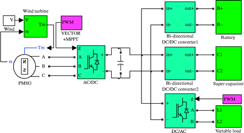
The proposed stand-alone wind power system consists of a wind turbine system, a permanent magnet synchronous generator (PMSG), an AC/DC converter, two bidirectional DC/DC converters, a vanadium redox flow battery, a supercapacitor, a DC/AC converter and a variable load. The structure of the stand-alone wind energy system with energy storage is provided in Figure .
In Figure , the AC/DC converter is shown as a full-control rectifier bridge that controls to capture maximum wind energy, and a vector control strategy is applied for the AC/DC converter. The input signal of the vector control comes from the output of the proposed MPPT control algorithm. Because the power may flow through the battery and the supercapacitor in both directions, a bidirectional DC/DC converter is selected for each of these devices. Two bidirectional DC/DC converters are connected directly to the DC bus. The DC/AC converter is a single-phase fully controlled inverter bridge and generates an AC voltage with some amplitude and frequency to meet the load demand. The load can also be directly connected to the DC bus or through a single directional DC/DC converter.
3. Control strategies
To achieve the energy balance of the system and maximise the utilisation efficiency of wind energy, the following optimal energy management strategies are proposed:
An MPPT control strategy is designed to capture maximum wind energy to make good use of wind resource.
When the power generated from the wind power system is greater than the load demand, then the excess power is stored in ways as follows. When the battery charging current is low, the excess power generated from the system charges the battery through bidirectional DC/DC converter 1. When the battery charging current exceeds the setting threshold, a part of the excess power generated from the system charges the supercapacitor through bidirectional DC/DC converter 2. In this case, both bidirectional DC/DC converters 1 and 2 operate in the buck mode.
When the power generated from the wind power system is less than the load power demand, the power supply is generated for the load through the DC/AC converter. The insufficient power is supplied in ways as follows. When the battery discharging current is low, the insufficient power is supplied by the battery for the DC bus through bidirectional DC/DC converter 1 to meet the high load power demand. When the battery discharging current exceeds the setting threshold, a part of the insufficient power is supplied by the supercapacitor for the DC bus through bidirectional DC/DC converter 2 to supply power for the load. In this case, both bidirectional DC/DC converters 1 and 2 operate in the boost mode.
The implementation of the aforementioned optimal energy management by the proposed control strategies is presented in the following sections.
3.1 MPPT control
3.1.1 Power characteristic of a wind turbine
According to the Bates theory (Munteanu et al. Citation2008), the power captured by a wind turbine from wind energy is given by
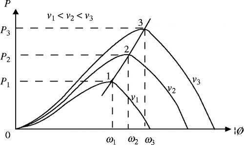
Based on Equation (1), Cp can be adjusted to capture wind energy. When the pitch angle is constant, Cp becomes a function of the tip speed ratio λ, where λ = ωR/v and ω is the rotating speed of the wind turbine. Figure shows the power characteristic of a wind turbine at different wind velocities, v, and wind turbine speeds, ω.
As shown in Figure , the wind turbine speed varies with the wind velocity to maintain a constant optimal tip speed ratio to capture maximum wind energy. In the following section, the MPPT control strategy is proposed to elucidate this objective.
3.1.2 SM ESC MPPT control
According to the ESC principle, for an unknown function y(x), let us assume that there exists a unique extreme value point, i.e. if y(x) is a convex function, then the ESC can find an x value that makes y(x) to obtain an extreme value by tracking x (Olalla et al. Citation2007).
Based on the power characteristics of a wind turbine, as shown in Figure , at a certain wind velocity v, there exists a unique turbine speed or the generator speed ω, and the wind turbine can capture extreme wind energy at this speed ω, i.e. the stator output active power of the generator reaches the extreme value. It means that the generator speed and the stator output active power form a convex function, so that the ESC can be applied to find a certain generator speed that makes the output active power of the wind power system to reach an extreme value.
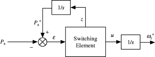
However, the conventional ESC needs speed and power differential terms to find an extreme value. Differential terms, as well as speed measurement, can be avoided if the SM control is introduced into the ESC structure (Korovin and Utkin Citation1972, Citation1974; Pan, Ji, and Jiang Citation2008). The design of an MPPT control block diagram based on the SM and ESC for the wind power system is shown in Figure .
As shown in Figure , Ps is the generator output active power, is the generated optimal reference value of the generator speed and
is the reference value of the maximum active power of the generator. The principle of the MPPT control design can be described by the following expressions.
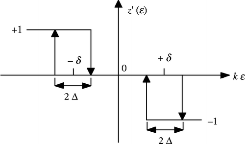
As shown in Figure , δ, Δ, and k are positive small constants. According to Equation (2),
The change in the sign of would result in the action of cutting into or cutting out the sliding surface. In the SM ESC MPPT control strategy design, the parameters involved are U0, Z0, δ, Δ and k. According to the simulation analysis at different wind velocities, a set of optimal parameters selected are U0 = 10,000, Z0 = 20, δ = 0.02, Δ = 0.01 and k = 0.0001.
3.2 AC/DC converter control
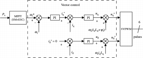
To capture the extreme power from the available wind resource, the AC/DC converter controls the electromagnetic torque of the generator according to the wind velocity. The vector control strategy is applied to the AC/DC converter, as shown in Figure . The optimal reference speed from the MPPT is the input of the vector control, and outputs of the vector control are the direct axis and the quadrant axis stator reference voltages,
and
, respectively. The space vector pulse modulation (SVPWM) unit outputs six-channel pulses according to
and
to control the AC/DC converter.
As shown in Figure , ud and uq are the direct axis and quadrant axis components of the generator stator voltage, id and iq are the direct axis and quadrant axis components of the generator stator current, Ld and Lq are the direct axis and quadrant axis components of generator inductance, ψf is the flux generated by permanent magnets and ωs is the synchronisation frequency.
The SVPWM strategy proposed by Pan and Chen (Citation2006) was used in this paper.
3.3 Charge/discharge controls for bidirectional converters
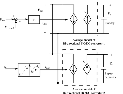
The battery and supercapacitor charge/discharge controls are shown in Figure . Two bidirectional DC/DC converters were simplified with an average model (Teleke et al. Citation2009).
As shown in Figure , bidirectional DC/DC converter 1 is controlled by the PI controller, and the input of the PI controller is the error between the reference DC bus voltage Vbus_ref and the measured DC bus voltage Vbus. The output of the PI controller is id1, which controls the input current of bidirectional DC/DC converter 1. If id1 < 0, the battery is discharged, otherwise the battery is charged. Bidirectional DC/DC converter 1 is controlled to maintain a constant DC bus voltage.
The controller of bidirectional DC/DC converter 2 is a deadzone function with variable parameters (Han et al. Citation2006). The deadzone starts from the threshold ib1 and ends with the threshold ib2; the slopes k1 and k2 control the current values dispatched from the battery. When the battery charging current reaches the setting threshold ib2 or the discharging current reaches the setting threshold ib1, bidirectional DC/DC converter 2 initiates its operation. When idc2 < 0, the supercapacitor is discharged, otherwise the supercapacitor is charged.
Ignoring the converter losses, according to the energy balance principle, the values of ib and ic can be computed as follows:
3.4 DC/AC converter control
The DC/AC converter is controlled by a PWM pulse generator, whose parameters are determined by the amplitude and frequency of voltage that are needed to supply power for the load.
4. Simulation results and discussion
The system presented here was modelled and simulated with MATLAB/Simulink. The air density (ρ) is 1.25 kg/m3 and the wind turbine blade radius (R) is 0.61 m. PMSG parameters are listed as follows: stator resistance, Rs = 0.78 Ω; direct axis and quadrant axis inductances, Ld = 0.0045 H and Lq = 0.0085 H; moment of inertia, J = 0.00321 kg m2 and number of pole pairs, p = 3. The model of a vanadium redox flow battery proposed by Chahwan, Abbey, and Joos (Citation2007) was used, whose parameters are listed as follows: normal battery voltage 60 V, capacity 3 A h and initial state of charge (SOC) 80%. The DC bus voltage is 400 V. The first-order model of a supercapacitor model proposed by Dougal, Gao, and Liu (Citation2004) was used, whose parameters are listed as follows: equivalent resistance 0.1 Ω, equivalent capacitance 120 F and initial voltage 200 V.
Parameters of the PWM pulse generator used for controlling the DC/AC converter are as follows: modulation ratio 0.6, carrier frequency 50 Hz and switching frequency 5 kHz.
4.1 Case 1: variable wind velocity and constant load power
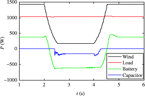
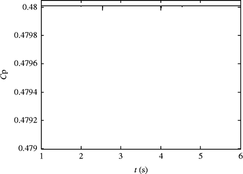
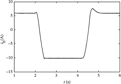
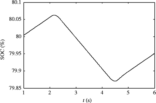
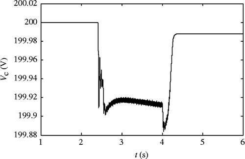
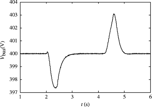
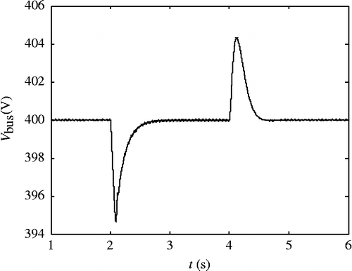
In this case, the wind velocity varies from 16 m/s (at t = 2 s) to 8 m/s (at t ≈ 2.5 s), and then backwards from 8 m/s (at t = 4 s) to 16 m/s (at t ≈ 4.5 s); the load power is 1050 W. Waveforms of the power from the wind turbine (wind), the battery (battery) and the supercapacitor (capacitor), and the load power demand (load) are shown in Figure . The wind energy capture coefficient is shown in Figure . The battery charging/discharging current and SOC are shown in Figures and , respectively. The supercapacitor voltage and the DC bus voltage are shown in Figures and , respectively.
Figure shows that when the wind velocity is varied, the power balance of the wind power system is maintained. During the transient event, the wind power cannot supply the total power for the load. Therefore, the difference in power is balanced by the battery and supercapacitor, which could meet the objectives of energy management strategies proposed in Section 2. Figure shows the MPPT control algorithm design, with Cp being constant at an optimal value of 0.481 when the wind velocity varies.
Figures show that the battery and the super-capacitor transfer from a charge to a discharge mode during the transient event. Figure shows that the DC bus voltage remains constant at 400 V.
4.2 Case 2: variable load power and constant wind velocity
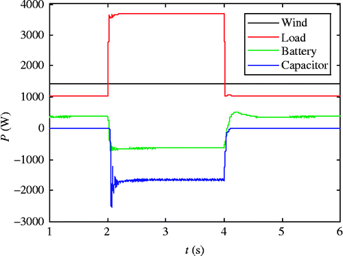
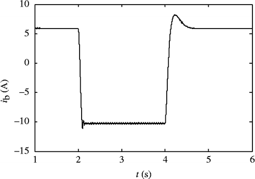
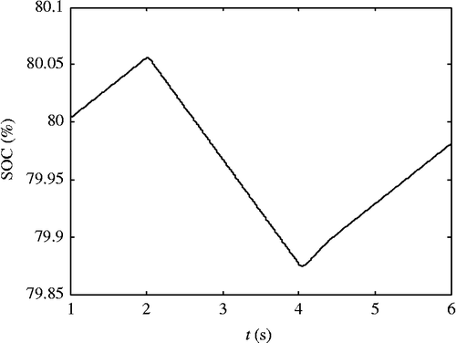
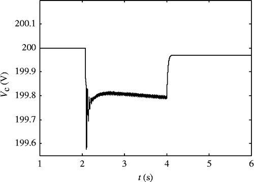
The load power varies from 1050 to 3700 W at t = 2 s, and then backwards from 3700 to 1050 W at t = 4 s. Waveforms of the power from the wind turbine (wind), the battery (battery) and the supercapacitor (capacitor), and the load power demand (load) are shown in Figure . The battery charging/discharging current and SOC are shown in Figures and , respectively. The supercapacitor voltage and the DC bus voltage are shown in Figures and , respectively.
Figure shows that when the load power is varied, the power balance of the wind power system is also maintained. During the transient event, the wind power cannot supply the total power for the load, therefore both the battery and the supercapacitor balance the difference in power. Figures show that the battery and the supercapacitor transfer from a charge to a discharge mode during the transient event. Figure shows that the DC bus voltage remains constant at 400 V.
5. Conclusion
This paper presents a stand-alone wind power system with hybrid energy storage that consists of three power sources: wind generation unit, battery and supercapacitor. These power sources and load are connected to the same DC bus through appropriate power converters by control strategies. An AC/DC converter along with a vector control and an MPPT control is used to capture maximum energy from wind resource. Two bidirectional charge/discharge controllers are designed to maintain a constant DC bus voltage and regulate the current flow from the battery to the supercapacitor to limit the battery charging/discharging current. The simulation results prove that the proposed method can rapidly respond to the variations in load power and wind velocity.
Acknowledgements
This work was supported by special grade of financial support from China Postdoctoral Science Foundation under contract 201003553, and Natural Science Foundation of Jiangsu Province under contract BK2012550.
REFERENCES
- Barote, L., C.Marinescu, and I.Serban. 2010. “Energy Storage for a Stand-Alone Wind Energy Conversion System.” Revue. Roumaine des Sciences Techniques-Serie Electrotechnique et Energetique55 (3): 235–242.
- Barote, L., R. Weissbach, R. Teodorescu, C. Marinescu, and M. Cirstea. 2008. “Stand-alone Wind System with Vanadium Redox Battery Energy Storage.” Paper presented at the annual meeting for the Society of The 11th International Conference on Optimization of Electrical and Electronic Equipment, Brasov, Romania, May 22–24.
- Borowy, B. S., and Z. M.Salameh. 1997. “Dynamic Response of a Stand-Alone Wind Conversion System with Battery Energy Storage to a Wind Gust.” Energy Conversion12 (1): 73–78.
- Chahwan, J., C. Abbey, and G. Joos. 2007. “VRB Modelling for the Study of Output Terminal Voltages, Internal Losses and Performance.” Paper presented at the annual meeting for the Society of Electrical Power Conference, Montreal, Que, Canada, October 25 and 26.
- De Broe, A. M., S.Drouillet, and V.Gevorgian. 1999. “A Peak Power Tracker for Small Wind Turbines in Battery Charging Applications.” IEEE Transactions on Energy Conversion14 (4): 1630–1635.
- Dougal, R. A., L.Gao, and S.Liu. 2004. “Ultracapacitor Model with Automatic Order Selection and Capacity Scaling for Dynamic System Simulation.” Journal of Power Sources126 (1): 250–257.
- El-Ali, A., J. Kouta, D. Al-Samrout, N. Moubayed, and R. Outbib. 2009. “A Note on Wind Turbine Generator Connected to a Lead Acid Battery.” Paper presented at the annual meeting for the Society of The 7th International Conference on Electromechanical and Power Systems ∼ SIELMEN’09 ∼. Iaşi, Romania, October 8 and 9.
- Han, C., A. Q. Huang, W. Litzenberger, L. Anderson, A.-A. Edris, M. Baran, S. Bhattacharya, and A. Johnson. 2006. “STATCOM Impact Study on the Integration of a Large Wind Farm into a Weak Loop Power System.” Paper presented at the annual meeting for the Society of IEEE Power System Conference and Exposition, Atlanta, GA, October 29–November 1.
- Hau, E.2006. Wind Turbines: Fundamentals, Technologies, Application, Economics. Germany: Springer.
- Knight, A. M., and G. E.Peters. 2005. “Simple Wind Energy Controller for an Expanded Operating Range.” IEEE Transactions on Energy Conversion20 (2): 459–466.
- Korovin, S. K., and V. I.Utkin. 1972. “The Use of the Slip Mode in Problems of Static Optimization.” Automatic and Remote Control (4): 50–60.
- Korovin, S. K., and V. I.Utkin. 1974. “Using Sliding Modes in Static Optimization and Nonlinear Programming.” Automatica10: 525–532.
- López, M., and J. C.Vannier. 2009. “Stand-Alone Wind Energy Conversion System with Maximum Power Transfer Control.” Ingeniare. Revista chilena de ingeniería17 (3): 329–336.
- Markel, T., M. Zolot, K. B. Wipke, and A. A. Pesaran. 2003. “Energy Storage System Requirements for Hybrid Fuel Cell Vehicles.” Paper presented at the annual meeting for the Society of Advanced Automotive Battery Conference, Nice, France, June.
- Munteanu, I., A. I.Bratcu, N. A.Cutululis, and E.Ceanga. 2008. Optimal Control of Wind Energy Systems. Towards a Global Approach. London: Springer.
- Olalla, C., M. I. Arteaga, R. Leyva, and A. El Aroudi. 2007. “Analysis and Comparison of Extremum Seeking Control Techniques.” Paper presented at the annual meeting for the Society of IEEE International Symposium on Industrial Electronics ∼ISIE∼, Vigo, Spain, June 4–7.
- Pan, T. L., and E. K.Chen. 2006. “A Novel Space-Vector PWM Controller Based on artificial-Neural-Network for Voltage-Fed Inverter Induction Motor Drive.” Dynamics of Continuous Discrete and Impulsive Systems-Seriesa-Mathematical Analysis13 (Part 4 Suppl. S): 1929–1936.
- Pan, T. L., Z. C. Ji, and Z. H. Jiang. 2008. “Maximum Power Point Tracking of Wind Energy Conversion Systems Based on Sliding Mode Extremum Seeking Control.” Paper presented at the annual meeting for the Society of IEEE Energy 2030, Atlanta, GA, USA, November 17 and 18.
- Teleke, S., M. E.Baran, A. Q.Huang, S.Bhattacharya, and L.Anderson. 2009. “Control Strategies for Battery Energy Storage for Wind Farm Dispatching.” IEEE Transactions on Energy Conversion24 (3): 725–732.
- Yoshimoto, K., T. Nanahara, and G. Koshimizu. 2006. “New Control Method for Regulating State-of-Charge of a Battery in Hybrid Wind Power/Battery Energy Storage System.” Paper presented at the annual meeting for the Society of IEEE Power System Conference and Exposition, Atlanta, GA, October 29–November 1.
- Zhang, Y., Z. H. Jiang, and X. W. Yu. 2008. “Control Strategies for Battery/Supercapacitor Hybrid Energy Storage Systems.” Paper presented at the annual meeting for the Society of IEEE Energy 2030, Atlanta, GA, USA, November 17 and 18.

