Abstract
Renewable and alternative fuels have numerous advantages compared with fossil fuels, as they are renewable and biodegradable, and provide food and energy security and foreign exchange savings besides addressing environmental concerns and socio-economic issues. In this context, present work was carried out to investigate the feasibility of alternative and renewable fuels derived from biomass feedstock of different origin for engine applications. The present study was also extended to study the effect of producer gas composition derived from different biomass feedstock on the performance, combustion and emission characteristics of a single-cylinder, four-stroke, direct injection stationary diesel engine operated on a dual-fuel mode using Honge oil methyl ester (HOME) and producer gas induction. The performance of the engine was evaluated with a constant injection timing of 27° before top dead centre, an injection pressure of 205 bar for the diesel–producer gas combination and 230 bar for the HOME–producer gas combination and a compression ratio of 17.5. The results showed that the performance of the dual-fuel engine varies with the composition of the producer gas and depends on the type of biomass feedstock used in the gasifier. Experimental investigations on the dual-fuel engine showed that brake thermal efficiency values for the engine operated using HOME–producer gas derived from babul, neem and honge woods were found to be 17.2, 14.3 and 11.56% respectively, compared to 23.8% for diesel–producer gas operation at 80% load. However, the results showed better engine performance with lower exhaust emission levels for the operation of HOME–producer gas derived from the ordinary or babul wood compared with the operation of that derived from the neem and Honge woods. In view of this, present study reveals that use of alternative and renewable fuels for dual fuel engine can be considered as an immediate solution for the development of rural areas and emergency use in the event of severe diesel fuel shortage.
Nomenclature
| bTDC | = | before top dead centre |
| BTE | = | brake thermal efficiency (%) |
| HC | = | hydrocarbon (ppm) |
| CO | = | carbon monoxide (%) |
| NOx | = | Nitric oxide (ppm) |
| ppm | = | parts per million |
| OW | = | ordinary or babul wood |
| NW | = | neem wood |
| HW | = | Honge wood |
| CA | = | crank angle |
| rpm | = | revolutions per minute |
1. Introduction
The life of conventional fossil fuels has become limited in the present era, where the use of energy and its source has been growing faster than the world population. It has been estimated that India has a surplus of about 120–160 million tonnes of agricultural residues every year, comprising mainly different woody biomass and agricultural residues corresponding to a potential of about 18,000 MW and a total installed capacity of biomass-based power of 2559 MW (Awasthi and Karishma Citation2013; Murugesan et al. Citation2009). The country has a potential to generate an additional 20 GW of electricity from biomass residues (Awasthi and Karishma Citation2013; Galik, Abt, and Wu Citation2009). On the global scale, due to the use of fossil fuels, there is an increased emission rate of greenhouse gases, creating a threat to the world climate. Conventional liquid fuels are the major contributor to energy sources. They might become extinct if used extensively. With declining fossil fuel resources and increased demand for their products, there is an urgent need to develop economical, environment-friendly, energy-efficient processes and resources for the production of fuels and chemicals. Therefore, the need to search for renewable and alternative fuels is essential to meet the demands of automotive, agricultural and power sectors. In this context, many researchers have studied different alternative fuels such as bio-diesels derived from various vegetable oils and producer gas for diesel engine applications. Therefore, a promising need to identify an alternative to petroleum products that is indigenous and renewable has gained greater importance.
Bio-diesels derived from non-edible vegetable oils present a very promising alternative to diesel oil. Renewable and alternative fuels have numerous advantages compared with fossil fuels, as they are renewable and biodegradable, and provide food and energy security and foreign exchange savings besides addressing environmental concerns and socio-economic issues. Bio-diesel operated diesel engine results in a slightly lower brake thermal efficiency with increased smoke, HC and CO emission levels. However, decreased NOx emission levels were reported. It could be attributed to the fact that biodiesel has lower calorific value and volatility and high molecular weight free fatty acids. The use of vegetable oils and their bio-diesels as compression ignition (CI) engine fuels has yielded promising results. The problems faced when using these oils in a diesel engine have been reported in the literature (Alptekin and Canakci Citation2009; Banapurmath et al. Citation2005; Banapurmath, Tewari, and Hosmath Citation2008; Canakci Citation2005; Demirbas Citation2005; Mehta and Ananda Citation2009; Sahoo, Das, et al. Citation2009; Sahoo, Sahoo, and Saha Citation2009; Scragg, Morrison, and Shales Citation2003; Zhang and Wangm Citation2007). Biomass contributes to one-seventh of the world energy consumption, has a great potential to be used as a renewable source and can be replaced with conventional fossil fuels. Even though India has a large wasteland (about 107 million hectares of degraded land and 64 million hectares of wasteland) and biomass resource, still they are utilizing them inefficiently. India produces about 450–500 million tonnes of biomass per year including sugarcane bagasse and leaves. In view of this, biomass-based power plants can be used very conveniently.
Biomass-based gasifier projects for decentralized power supply and financial evaluation have been reported in the literature (Nouni, Mullick, and Kandpal 2007; Ravindranath and Balachandra Citation2009). Producer gas is considered to be a good alternative fuel for stationary engines for power generation, which can provide a good environmental effect. However, variations in the composition of producer gas during the experimental investigations have been found to affect the performance, combustion and emission characteristics of a dual-fuel engine. Properties of various biomass feedstock and their effects on the gasification process have been reported in the literature (Asri and Ichiro Citation2007; Bhattacharya and Chinmoy Citation2009; Churchill et al. Citation1986; Evandro et al. Citation2010; Jorapur and Rajvanshi Citation1993; Mark Jan Prins 2005; Mihai and Cornelia Citation2010; Pasangulapati et al. Citation2012; Pratik and Babu Citation2009; Ramadas, Jayaraj, and Muraleedharan Citation2006; Naik et al. Citation2010; Sridhar et al. Citation2005; Uma et al. Citation2004). Producer gas can be employed in an existing diesel engine with minor engine modifications. These modifications include gasifier and engine operating parameters, gasifier–engine integration with suitable cooling and cleaning systems and gas induction facility with a carburettor to ensure stoichiometric producer gas–air supply to the engine. Gasification technology, pyrolysis options, potential scope from the routes such as hydrogen, charcoal production, properties of producer gas, variations in temperatures and pressure drop across the gasifier with different fuels, fuel consumption and economic analysis of the gasifier system have been reported previously (Bridgwater, Toft, and Brammer Citation2002; Ravindranath and Balachandra Citation2009; Panwar et al. Citation2009, Citation2012; Rathore et al. Citation2009; Panwar 2011). The performance of a dual-fuel engine depends on the physical and chemical properties of biomass, fuel type and moisture, combustion phase, air supply conditions and several other variables. Many investigators have extensively studied gasifier–engine systems for both rural and urban power applications (Banapurmath, Tewari, and Hosmath Citation2008; Banapurmath et al. Citation2009, Citation2011; Cenk Sayin and Gumus Citation2011; Muralidharan and Vasudevan Citation2011; Nouni, Mullick, and Kandpal Citation2007; Parikh et al. Citation1989; Ramadas, Jayaraj, and Muraleedharan Citation2006; Ravindranath and Balachandra Citation2009; Rehaman and Ghadge 2008; Singh, Singh, and Pathak Citation2007; Sridhar et al. Citation2005). Biomass can be utilized through different processes for energy conversion (Bridgwater, Toft, and Brammer Citation2002). Energy derived from biomass is rather expensive due to its lower conversion efficiencies and logistic constraints. The performance of gasifier–engine systems using high-speed direct injection (DI) and low-speed indirect injection engines operated using a diesel–producer gas combination has been reported earlier (Parikh et al. Citation1989). A producer gas-fuelled dual-fuel engine has been reported to result in a lower BTE and a higher exhaust gas temperature (EGT) (Singh, Singh, and Pathak Citation2007; Samir, Lalit, and Shashikant Citation2008; Banapurmath and Tewari Citation2009; Banapurmath et al. Citation2009, Citation2011; Ramadas, Jayaraj, and Muraleedharan Citation2006, Citation2008). However, a small increment in BTE has been observed for an advanced injection timing and an increased compression ratio. Several investigators have observed increased hydrocarbon (HC) and carbon monoxide (CO) emission levels for a dual-fuel mode of operation (Banapurmath et al. Citation2009, Citation2011; Mohod, Gadge, and Madansure 2003; Parikh et al. Citation1989; Ramadas, Jayaraj, and Muraleedharan Citation2008; Sahoo, Das, et al. Citation2009; Sahoo, Sahoo, and Saha Citation2009). The effect of pilot fuel injection, injection timing and injection pressure on the performance and exhaust emission levels of a supercharged producer gas - diesel-fuelled dual-fuel engine has been investigated. Better engine performance was reported with higher injection pressures than lower ones. Higher nitric oxide emission levels have been found at maximum power conditions (Roy et al. Citation2009; Hassan et al. Citation2011). Researchers have investigated fuel substitution for a dual-fuel engine and reported a fuel substitution of about 60–90% (Banapurmath and Tewari Citation2009; Banapurmath et al. Citation2009, Citation2011; Parikh et al. Citation1989; Ramadas, Jayaraj, and Muraleedharan Citation2006, Citation2008; Samir, Lalit, and Shashikant Citation2008; Singh, Singh, and Pathak Citation2007). It has been reported that the performance of a producer gas-based dual-fuel engine is greatly affected by the quality of the producer gas and depends on the gasifier fuel, design and operating characteristics (Banapurmath et al. Citation2009, Citation2011).
A theoretical understanding of the combustion and gasification of a variety of biomass feedstock has made a significant progress during the past decades. The effect of biomass feedstock, carburettor and ethanol blending on the performance of a dual-fuel engine has been investigated in the literature. A negative point concerning producer gas-fuelled dual-fuel engines has always been the necessity of constant monitoring and fine tuning of the carburettor in order to achieve satisfactory performance (Anil et al. Citation2006; Azzoni, Minelli, and Moro Citation1999; Banapurmath et al. Citation2011; Deshmukh, Bhuyar, and Thakre Citation2008; Jingura, Musademba, and Matengaifa Citation2010; Ohyama Citation1999; Tseng and Cheng Citation1999; Rathore, Panwar, and Vijay Chiplunkar Citation2008; Sridhar et al. Citation2005).
1.1 Use of biomass feedstock for gasification
Biomass oxidation is mainly because of carbon (C), hydrogen (H) and oxygen (O) present in the cellulose, hemicellulose and lignin contained in the cellular structure of biomass. Cellulose and hemicellulose are carbohydrates formed by the basic building blocks of glucose, galactose, mannose, xylose and arabinose and are responsible for better quality wood for energy applications. Lignin is a high-molecular-weight complex polymer and not a carbohydrate. The quality of producer gas generated from the gasifier depends on the composition, type of wood and operating characteristics. The properties of a single species are relatively constant within limits. However, single species may sometimes be with slight difference in its composition. Even though wood is a natural source, a variation in properties is due to many changing influences such as moisture, soil and weather conditions. However, for gasification or any other energy applications, specific chemical and physical properties must be considered and are the determining factors in identifying the suitability of biomass (Anjireddy and Sastry 2001).
However, the performance of a dual-fuel engine is affected by the components of biomass including cellulose, hemicellulose, lignin, lipids, proteins, sugars, starches, water, HC, ash and other compounds. The investigation of biomass properties would help in finding not only suitable and appropriate energy conversion technologies, but also different existing conversion technologies for the effective use of biomass feedstock. The pyrolysis rate in a gasifier becomes faster when the biomass contains a higher level of cellulose and hemicellulose. However, the presence of a higher amount of lignin makes the pyrolysis rate slower in a gasifier. The combustion characteristic of a biomass depends on the char morphology produced. Trees with increased biomass and reduced lignin would provide a good yield for the production of biofuels. Biomass composition can significantly affect gas evolution profiles. In view of this, biomass feedstock need to be well characterized before the selection of the gasification process (Asri and Ichiro Citation2007; Evandro et al. Citation2010; Mihai and Cornelia Citation2010; Pasangulapati et al. Citation2012; Naik et al. Citation2010).
Ignition temperature is affected by the presence of higher amounts of organic compounds in biomass. A higher H/C ratio results in higher gasification efficiency, whereas a higher O/C ratio leads to lower gasification efficiency. This could be attributed to the higher biomass oxidation at higher gasification temperatures. Also, biomass with a higher O/C ratio has a smaller heating value than that with a lower O/C ratio. However, biomass thermodynamic properties are not well known, except those for cellulose and hemicellulose, because the structure of these fuels is not well defined. In view of this, statistical correlations have been developed to overcome this problem (Mark Jan Prins Citation2005). The exhaustive literature survey undertaken has clearly provided a direction to undertake the present study, as the published work highlighted less significance on the composition and effect of different types of biomass feedstock properties on the performance of a dual-fuel engine. In this context, an effort has been made to study the effect of cellulose, hemicellulose and lignin content of biomass along with their physico-chemical properties on the performance of a diesel engine operated on dual-fuel mode, as it is less investigated in detail in the already published literatures. For the present study, Honge tree was selected, which can provide both the liquid fuel as an alternative to diesel oil and the biomass feedstock to the gasifier for the successful operation of a gasifier–engine integrated system.
1.2 Present work
In this study, an effort was made to evaluate the feasibility of alternative and renewable fuels (liquid fuel and different biomass feedstock) in the form of Honge oil methyl ester (HOME) and producer gas derived from biomass feedstock of different origin as a complete replacement for fossil fuels. For this purpose, experiments were conducted on a single-cylinder, four-stroke, direct injection diesel engine operated on a dual-fuel mode at an advanced injection timing of 27° before top dead centre (bTDC), a compression ratio of 17.5 and an injection pressure of 205 bar for the diesel–producer gas operation and 230 bar for the HOME–producer gas operation. The optimum parameters in terms of advanced injection timing and increased injection pressure have been reported in earlier studies by the same authors (Banapurmath, Tewari, and Hosmath Citation2008; Banapurmath et al. Citation2009, Citation2011). Finally, the results were compared with baseline data and analysed.
2. Characterization of the fuels used
The properties of biomass feedstock are the key factors that influence the performance, combustion and emission levels of a dual-fuel engine. Therefore, the characterization of biomass is the first step for the efficient utilization of its energy potential. However, in order to use biomass efficiently for energy production, a detailed knowledge of its physical and chemical properties is essential, because the gasification process is very sensitive to fuel quality. The proximate analysis of the fuel provides the information on the combustion characteristics of the biomass feedstock. The characterization of all the selected samples showed that they are potential candidates for the generation of producer gas. The properties of the fuels used were determined at a Bangalore test house and college laboratory in India. Table shows the properties of liquid fuels and the proximate and ultimate analysis of the biomass feedstock used in the present study. The composition of the wood and that of the producer gas derived from different biomass feedstock are shown in Tables and , respectively.
Table 1 Properties of liquid fuels and proximate and ultimate analysis of biomass feedstock.
Table 2 Composition of the wood.
Table 3 Composition of the producer gas.
Honge tree is also called Karanja. This tree is chiefly found along the banks of streams and rivers or near the sea coast. It grows in dry places and attains heights of 15–18 m. It is often grown as a roadside avenue tree all over India. The expected life of this tree is 40–50 years and its potential yield on maturation is about 5000 kg per hectare.
Acacia nilotica Linn. is a tree belonging to the Leguminosae family and the subfamily Mimosaceae. It is a moderately sized tree with a spreading crown, spiny, having dark bark brown to almost black and an evergreen tree with a short, thick and cylindrical trunk found throughout India. It is also called babul, Kikar and Babur (Hindi). The babul tree grows in a scattered fashion and occurs in groups naturally. It attains a height of 15–20 m and a girth of 2.4–3.0 m, and is a stunted, shrubby or straggling tree. This species is abundant particularly in Karnataka. A. nilotica can regenerate naturally. The species occurs in patches, usually in wastelands and common grazing lands. The wood contains 5–15% of moisture and traces of sugar, and yields 2.0–3.5% of ash, comprising 29% of oleic acid and 44.5% of linoleic acid and other traces of gallic acid, digallic acid, chlorogenic acid, etc.
The neem tree also known as the Indian lilac or margosa tree has the scientific name Azadirachta indica and belongs to the family of Meliaceae. Full-grown neem trees yield between 10 and 100 tonnes of dried biomass per hectare, depending on rainfall, site characteristics, spacing, ecotype or genotype, and are fast-growing trees that can be established without irrigation in many arid regions. Neem is a large tree attaining a height of about 25 m with a semi-straight to straight trunk, a girth of 3 m and spreading branches forming a broad crown. A neem tree normally starts fruiting after 3–5 years.
3. Experimental set-up
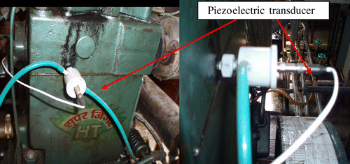
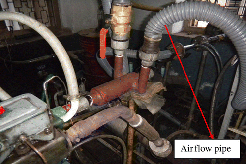
Experimental investigations were conducted on a single-cylinder, four-stroke, water-cooled, direct injection CI engine, as shown in Figure . The specifications of the engine are given in Table . Engine loading was varied using an eddy current dynamometer. The experiments were conducted at a constant speed of 1500 rpm with varying load conditions. The test engine has conventional fuel injection system and it has a nozzle having three holes. Each nozzle hole is 0.3 mm diameter with a spray angle of 120°. Fuel was needed to maintain a constant speed by adjusting the governor lever so that the injected fuel quantity varied depending on the engine load, and the flow rate of the producer gas was maintained nearly constant. The mass of different fuels was measured on a volumetric basis. The injector opening pressure, the static injection timing and the compression ratio were 205 bar, 23° bTDC and 17.5, respectively, according to the engine manufacturer's specifications. However, for the dual-fuel mode of operation, injection timing, injection pressure and compression ratio were kept at 27° bTDC, 205 bar and 17.5 respectively and injection pressure was changed to 230 bar for HOME–producer gas operation. The engine had a hemispherical combustion chamber with overhead valves operated through push rods. Engine-Soft is a software used for the communication of the data between the test rig and the data acquisition system through a control panel. Engine-Soft can serve most of the engine testing application needs including monitoring, reporting, data entry and data logging. The software evaluates power, efficiencies, fuel consumption, heat release and pressure–crank angle (CA) diagram. It is configurable as per the engine set-up. The cooling of the engine was accomplished by the water circulating through the jackets of the engine block and the cylinder head. A piezoelectric pressure transducer was mounted onto the cylinder head surface to measure the cylinder pressure, as shown in Figure . The exhaust gas analyser and the smoke meter were used to measure the emission levels of HC, CO and NOx and smoke opacity. Tables present the specifications of the piezoelectric transducer, the smoke meter, the exhaust gas analyser and the eddy current dynamometer, respectively. For air and gas mixing, a parallel flow gas entry carburettor was used for the experiment, as shown in Figure . All the measurements were done when the engine attained a steady state. For each load, five readings were generated to ensure the accuracy of the data recorded and careful experimental arrangements were made to obtain consistent and repeatable measurements.
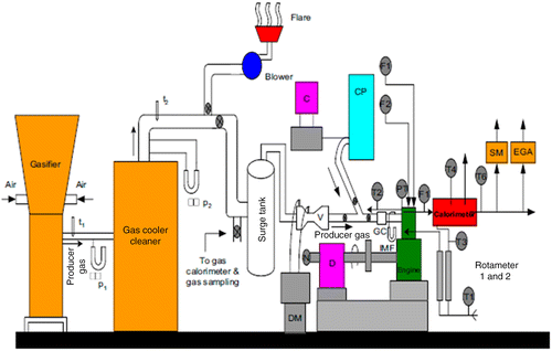
Table 4 Specifications of the experimental test rig.
Table 5 Specifications of the pressure pick-up.
Table 6 Specifications of the smoke meter.
Table 7 Specifications of the exhaust gas analyser.
Table 8 Specifications of the dynamometer.
3.1 Downdraft gasifier
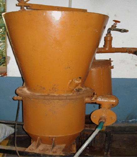
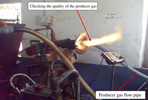
In the present study, for the generation of the producer gas, a downdraft gasifier was used, as it reduces the amount of high-molecular-weight HCs and particles when compared with the updraft configuration (McKendry Citation2002; Deshmukh, Bhuyar, and Thakre 2008; Banapurmath, Tewari, and Hosmath Citation2008). For the operation of a dual-fuel engine, the gasifier was coupled to the diesel engine. Figure shows a schematic diagram of a downdraft gasifier. Figure shows flaring for checking the quality of the producer gas. Table shows the specifications of the downdraft gasifier. Gasifiers are the reactors in which the gasification of the solid fuel takes place resulting in combustible gas called producer gas. The internal diameter in most of the downdraft gasifiers was reduced in order to create throat. Air inlet nozzles are commonly set radially round the throat to distribute the air as uniformly as possible. The pyrolysis zone is above the combustion zone and the reduction zone is below it. Fuel is fed from the top and the air flows in the downward direction through the combustion and reduction zones. The movement of the air is in the same direction as that of the fuel. The downdraft gasifier is designed in a way such that the tars in the pyrolysis zone are drawn through the combustion zone wherein a high amount of them will be cracked and reduced to non-condensable gaseous products before leaving the gasifier. High-molecular-weight HCs are cracked when they are passed through the high temperature zone. The rate of oxidation and reactions such as tar cracking are interrelated through the temperature parameter. Oxidation zone products are combustion products, cracked and uncracked pyrolysis products and water vapour. These products are then passed through the reduction zone, where reduction reactions take place. Sometimes the gasifier jacket is cooled by the incoming air, which heats the incoming air and boosts the production of CO. The narrow air stream entering into the gasifier causes a small zone of the fuel pile to burn very quickly at a very high temperature. This generates the producer gas rapidly. Thereafter, the producer gas is cooled and cleaned in a cooling and cleaning system and is made to flow through a calibrated venturimeter into the engine intake manifold. The process of cooling and cleaning is essential as the producer gas cannot be directly used for engine applications. The uncleaned gas contains tar that may affect the engine performance severely with wear and tear of the engine components.
Table 9 Specifications of the downdraft gasifier.
4. Results and discussion
This section presents the results of the investigation carried out on a single-cylinder, DI engine operated on a dual-fuel mode using diesel/HOME along with the producer gas derived from biomass feedstock of different origin.
4.1 Performance characteristics
4.1.1 Brake thermal efficiency
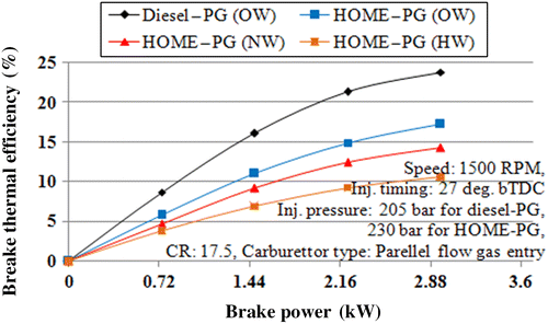
The generation of the producer gas from a variety of biomass feedstock resulted in the variations of BTE under a dual-fuel mode of operation. The BTE (Figure ) was found to be higher for the diesel–producer gas operation compared with the HOME–producer gas operation over the entire load range. A reduced BTE observed for the HOME–producer gas dual-fuel engine was mainly due to a lower air/fuel equivalence ratio, the combined effect of a lower calorific value of HOME and producer gas, a higher viscosity and low volatility characteristic and an increased ignition delay of HOME in the presence of the slow-burning producer gas. A lower adiabatic flame temperature and the flame velocity of the producer gas were also responsible for the observed trend. However, reduced turbulent flame propagation with the producer gas and increased compression work lower the efficiency. The equivalence ratios for HOME–producer gas derived from ordinary or babul wood (OW), neem wood (NW) and Honge wood (HW) operation were found to be 0.58, 0.52 and 0.46, respectively, and 0.66 for diesel–producer gas (OW) operation at the 80% load. It clearly indicates that there is insufficient air for the complete combustion of the HOME–producer gas combination. The results obtained are in good agreement with those reported in the literature (Banapurmath, Tewari, and Hosmath Citation2008; Banapurmath et al. Citation2011; Dasappa et al. Citation2011; Ramadas, Jayaraj, and Muraleedharan Citation2008).
It was observed that the properties of the injected fuel and the quality of the producer gas have a major effect on the engine performance. For the same injected fuels, higher BTE was observed with HOME–Producer gas (OW) operation compared to the dual–fuel operation with HOME–producer gas (NW) and HOME–producer gas (HW) combination over entire load range. This could be due to the better quality of the producer gas derived from the OW (babul), as it has high cellulose, carbon and hydrogen levels, calorific value and density compared with that derived from the NW and HW. The performance of the HOME–producer gas derived from the HW was much lower due to the presence of a higher ash content and its lower density resulting in a lower cylinder temperature. The BTE of the dual-fuel engine operated using HOME–producer gas derived from the OW (babul), NW and HW were found to be 17.2, 14.3 and 10.56%, respectively, that for the diesel–producer operation was found to be 23.8%.
4.1.2 Exhaust gas temperature
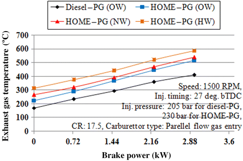
The EGT of the dual-fuel engine mainly depends on how much energy is supplied to the engine, the nature of the combustion process inside the engine cylinder and the quality of the producer gas derived from biomass feedstock of different origin. Figure shows the variations in EGT with brake power. It was observed that the EGT for the HOME–producer gas operation is higher than that for the diesel–producer gas operation. It could be due to the fact that decreased premixed combustion leads to the incomplete combustion of the HOME–producer gas combination and most of the fuel combination burns during the diffusion combustion phase rather than during the premixed combustion phase. The results of the present study are in close agreement with those reported in the literature (Banapurmath, Tewari, and Hosmath Citation2008; Banapurmath et al. Citation2011; Parikh et al. Citation1989; Ramadas, Jayaraj, and Muraleedharan Citation2008).
However, HOME–producer gas (OW) resulted in a slightly lower EGT compared with HOME–producer gas derived from the NW and HW. It is attributed to the presence of high ash and poor quality producer gas in the combustion process leading to incomplete combustion. However, the presence of the lignin content in the biomass feedstock may be responsible for the observed trend. The values of the EGT were found to be 515°, 540° and 585° CA for the HOME–producer gas (OW), HOME–producer gas (NW) and HOME–producer gas (HW) operations, respectively, compared with 410° CA for the diesel–producer gas (OW) operation at the 80% load.
4.1.3 Volumetric efficiency
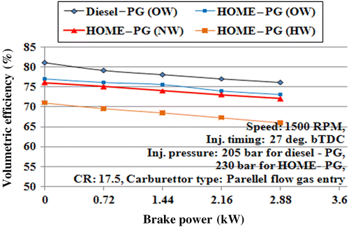
Figure shows the variations in volumetric efficiency for the diesel–producer gas and different HOME–producer gas operations. Volumetric efficiency indicates the breathing ability of an engine. The results showed a drop in volumetric efficiency for all the fuel combinations. It may be due to a higher gas temperature because of a higher inlet valve temperature. This feature decreases the density of the induced air, resulting in a drop in volumetric efficiency. It could also be due to the fact that some part of the air was replaced by the producer gas. The diesel–producer gas operation resulted in better volumetric efficiency compared with the HOME–producer gas operation. This could be attributed to the reduced pumping performance of the entire inlet system during the HOME–producer gas operation, and the improper utilization of the air leads to a higher EGT (Parikh et al. Citation1989; Banapurmath, Tewari, and Hosmath Citation2008; Banapurmath et al. Citation2009, Citation2011). However, the use of HOME–producer gas (HW) resulted in slightly lower volumetric efficiency compared with that of HOME–producer gas derived from the OW (babul) and NW. It could be due to higher EGT resulted from HOME–producer gas (HW) operation compared to HOME–producer gas derived from OW and NW operation. Also, presence of higher levels of poor quality producer gas in the combustion process is responsible for this trend. The volumetric efficiency values were found to be 73, 72.01 and 66.1% for the HOME–producer gas (OW), HOME–producer gas (NW) and HOME–producer gas (HW) operations, respectively, compared with 76.1% for the diesel–producer gas (OW) operation at the 80% load.
4.2 Emission characteristics
Emission characteristics of an engine are important as far as environmental aspects are concerned. The emission of gases from the engine indicates the quality of the combustion process that takes place inside the engine. The variations in producer gas composition and the lack of feedstock homogeneity (Banapurmath et al. Citation2011) and the type of liquid fuel, engine type (Parikh et al. Citation1989), design and operating parameters (Banapurmath, Tewari, and Hosmath Citation2008; Banapurmath et al. Citation2009, Citation2011), fuel inlet temperature, high or low load and speed operation (Sahoo, Saha, and Sahoo Citation2011; Roy et al. Citation2009) and ambient conditions are responsible for the observed trend. The emission levels during the producer gas operation under a dual-fuel mode were measured under the steady-state condition using calibrated instruments. The different exhaust emission measurements during the dual-fuel mode of operation are presented in the following sections.
4.2.1 Smoke opacity
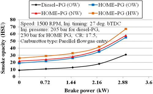
Smoke opacity was lower for the diesel–producer gas-fuelled dual-fuel operation compared with the HOME–producer gas operation over the entire load range (Figure ). The heavier molecular structure of the injected bio-diesel and the incomplete combustion of the fuel combination are responsible for higher smoke levels. The lower air/fuel equivalence ratio for the HOME–producer gas combination is also one of the reasons for higher smoke levels. Smoke opacity was found to be lower for the HOME–producer gas (OW) operation compared with the HOME–producer gas derived from the NW and HW for the dual-fuel operation over the entire load range. This could be due to incomplete combustion caused by the presence of HOME along with higher levels of poor-quality producer gas (derived from HW and NW) in the combustion process. Higher-molecular-weight fatty acids present in HOME, lignin and ash content, lower density and calorific value of the NW and HW are responsible for the presence of higher levels of poor-quality gas, leading to incomplete combustion inside the engine cylinder. The smoke opacity of the dual-fuel engine operated using HOME–producer gas derived from the OW, NW and HW was found to be 55, 58 and 67 HSU (Hartridge smoke unit), respectively, and 31 HSU for the diesel–producer operation.
4.2.2 HC and CO emissions
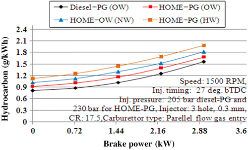
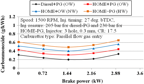
The HC and CO emissions were found to be lower for the diesel–producer gas-fuelled dual-fuel operation compared with the HOME–producer gas combination over the entire load range (Figures and , respectively). It could be due to incomplete combustion because of the heavier molecular structure of the injected bio-diesel fuel, the lower adiabatic flame temperature of the producer gas, the lower calorific value of HOME and producer gas, higher viscosity and the low volatility character of HOME in the presence of the slow-burning producer gas and insufficient oxygen available for combustion. The increased wall quenching of the flame and the lower mean effective pressure are also responsible for the observed trend. CO emissions were found to be increased to higher values as the equivalence ratio was lower for the dual-fuel operation and some part of the air was replaced by the producer gas (Banapurmath, Tewari, and Hosmath Citation2008; Banapurmath et al. Citation2008, Citation2011; Dasappa et al. 2011; Roy et al. Citation2009; Sahoo, Das, et al. Citation2009; Sahoo, Sahoo, and Saha Citation2009; Sridher et al. Citation2005; Ramadas, Jayaraj, and Muraleedharan Citation2008; Singh, Singh, and Pathak Citation2007).
Of all the woody biomass, dual-fuel operation with the OW resulted in lower HC and CO emission levels compared with the operation with the NW and HW. A lower lignin content, a comparatively higher hydrogen content in OW, a higher calorific value, a higher density and an acceptable moisture content of OW resulted in better combustion compared with the dual-fuel operation with the NW and HW, leading to a slightly lower HC and CO emission levels. Engine operation at lower load, comparatively higher CO emission levels were observed in the exhaust. This could be attributed to the presence of higher CO levels in the producer gas itself. Also, a higher molecular weight of bio-diesel, lignin content and the presence of ash in the producer gas and incomplete combustion due to the presence of higher levels of poor-quality producer gas are responsible for the observed trend. The HC emission levels of the dual-fuel engine operated using HOME–producer gas derived from the OW, NW and HW were found to be 1.68, 1.82 and 1.98 g/kW h, respectively, and 1.48 g/ kW h for the diesel–producer operation. The CO emission levels of the dual-fuel engine operated using HOME–producer gas derived from the OW, NW and HW were found to be 0.44, 0.56 and 0.65 g/kW h, respectively, and 0.33 g /kW h for the diesel–producer operation.
4.2.3 NOx emission
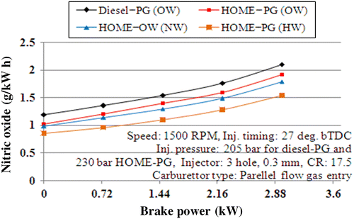
The NOx emission levels (Figure ) were found to be higher for the diesel–producer gas-fuelled dual-fuel operation compared with the HOME–producer gas operation over the entire load range. This could be due to a higher heat release during premixed combustion phase for the operation of diesel–producer gas combination. This is the reason why BTE is higher for diesel–producer gas operation. This could also be attributed to the lower adiabatic flame temperature of the producer gas, the lower air/fuel equivalence ratio over the entire load range, the unavailability of oxygen for combustion, the heavier molecular structure of HOME and the absence of organic nitrogen in the producer gas.
With HOME being common, the producer gas derived from OW results in slightly higher NOx emission levels compared with that derived from the NW and HW. This may be due to the presence of comparatively higher cellulose and hemicellulose and lower lignin content in the OW. It could also be to the generation of better quality gas from the combustion of OW biomass and presence of oxygen in a HOME favors the combustion. Also, this could be attributed to the higher heat release during the premixed combustion phase. The NOx emission levels of the dual-fuel engine operated using HOME–producer gas derived from the OW, NW and HW were found to be 1.893, 1.73 and 1.5432 g/kW h, respectively, and 2.1 g/kW h for the diesel–producer operation.
4.3 Fuel substitution
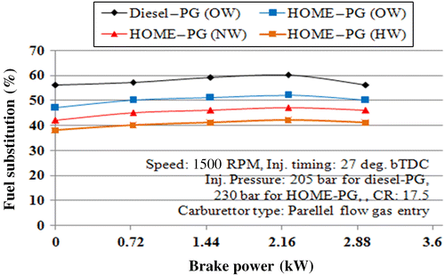
Figure presents the fuel substitution for the dual-fuel operation at different power outputs. The fuel substitution values were found to be higher for the diesel–producer gas operation compared with the HOME–producer gas operation over the entire load range. Injected fuel properties such as cetane number, viscosity and calorific value may be responsible for the observed trend (Banapurmath, Tewari, and Hosmath Citation2008; Banapurmath et al. Citation2011; Dasappa et al. 2011; Parikh et al. Citation1989). The percentage of fuel substitution was found to be higher for the HOME–producer gas operation with OW than for the operation with the NW and HW over the entire load range. The lower density and calorific value and the comparatively high moisture and ash content present in the NW and HW biomass feedstock could be the reason for this lower percentage of fuel substitution.
It was observed that fuel substitution for the HOME–producer gas (OW) operation was found to be slightly higher than that for the HOME–producer gas (HW) operation. The slightly higher calorific value and the better quality of the producer gas resulting from the burning of HOME–producer gas derived from OW may be responsible for the observed trend. The fuel substitution values of the dual-fuel engine operated using HOME–producer gas derived from the OW, NW and HW were found to be 50, 46 and 42%, respectively, and 56% for the diesel–producer operation.
4.4 Combustion analysis
The combustion in a diesel engine differs when gaseous fuels are used. Different combustion characteristics are presented in the following sections.
4.4.1 Ignition delay
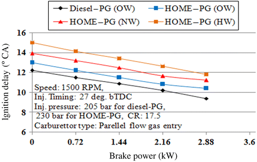
The effect of brake power on ignition delay is shown in Figure . The ignition delay is calculated based on the static injection timing. The HOME–producer gas operation resulted in a longer ignition delay compared with the diesel–producer gas operation. This could be due to the presence of oxygen in a HOME, that leads to the difference in the air/fuel ratio. It is also due to improper burning of HOME in presence of slow-burning producer gas. A better mixing of the air and the liquid fuel before the rapid combustion phase is a primary requirement in a diesel engine operation. An improper mixing of the fuel combination and lower chemical kinetics during the ignition delay (due to higher viscosity and density with reduced volatility of HOME compared with the diesel fuel and the slow-burning nature of the producer gas) is responsible for the observed trend. The HOME–producer gas (OW) operation results in a slightly lower ignition delay when compared with the HOME–producer gas (NW) and HOME–producer gas (HW) operations. This could be due to the presence of higher ash and lignin contents, the lower calorific value and the poor quality of the producer gas derived from the NW and HW. The values of the ignition delay were found to be 10.9°, 11.12° and 11.8° CA for the HOME–producer gas (OW), HOME–producer gas (NW) and HOME–producer gas (HW) operations, respectively, compared with 9.45° CA for the diesel–producer gas (OW) operation at the 80% load.
4.4.2 Combustion duration
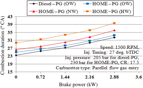
The combustion duration, shown in Figure , was calculated based on the duration between the start of combustion and the 90% cumulative heat release. The combustion duration increases with an increase in the power output for all the fuel combinations. This is due to an increase in the quantity of the injected fuel. A higher combustion duration was observed for the HOME–producer gas operation and a lower one for the diesel–producer gas operation. This could be attributed to a longer ignition delay. However, from Figure , it can be observed that the combustion duration was reduced for the HOME–producer gas (OW) operation compared with the HOME–producer gas (NW and HW) operation. This may be due to the improper burning of HOME–producer gas (derived from NW and HW) combination and reduced heat release rate during the combustion of HOME–producer gas (NW) and HOME–producer gas (HW) operations. The second peak was observed during the diffusion-burning phase and was greater for the HOME–producer gas operation than for the diesel–producer gas operation. This could be due to the higher viscosity of HOME and the reduction in air–fuel mixing rates along with the slow-burning producer gas. This leads to less fuel being prepared for rapid combustion for the HOME–producer gas operation after the ignition delay. Therefore, more burning occurs during the diffusion phase rather than during the premixed phase for the HOME–producer gas operation. Significantly higher combustion rates during the later stages for HOME–producer gas operation lead to higher exhaust temperatures and lower BTE. However, the HOME–producer gas (OW) operation shows a slightly lower combustion duration due to the improved heat release rate when compared with the HOME–producer gas (NW) and HOME–producer gas (HW) operations. This may be attributed to the comparatively higher calorific value and the better quality of the producer gas. The values of the combustion duration were found to be 32.45°, 36.8° and 39.2° CA for the HOME–producer gas (OW), HOME–producer gas (NW) and HOME–producer gas (HW) operations, respectively, compared with 31.4° CA for the diesel–producer gas (OW) operation at the 80% load.
4.4.3 Cylinder pressure
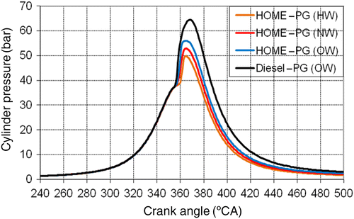
Figure shows in-cylinder pressure versus CA for the different HOME–producer gas and diesel–producer gas combinations at the 80% load. The peak pressure depends on the combustion rate and amount of fuel consumption during rapid combustion phase. The uncontrolled combustion phase is governed by the ignition delay period and by the mixture preparation during the delay period. Therefore, mixture preparation and the slow-burning nature of the producer gas during the delay period are responsible for the variations in peak pressure and the maximum rate of pressure rise. It was observed that the cylinder pressure for the HOME–producer gas combination was found to be lower than that for the diesel–producer gas combination.
The results showed that diesel–producer gas results in higher peak pressure, as shown in Figure . The cylinder pressure for the HOME–producer gas (OW) combination was found to be higher than that for the HOME–producer gas (NW) and HOME–producer gas (HW) combinations. This could be attributed to the longer ignition delay caused by the combined effect of higher viscosity and low volatility of HOME and the poor quality of the producer gas derived from the HW. The presence of a higher lignin content in a wood may result in slower combustion. Based on the results obtained, the second peak during the diffusion-burning phase was observed for the HOME–producer gas (HW) combination compared with the HOME–producer gas (OW and NW) combination under the dual-fuel mode of operation. This may be due to the higher viscosity of vegetable oils, the poor-quality of the producer gas, the reduction in air entrainment and fuel/air mixing rates along with the slow-burning nature of the producer gas.
4.4.4 Heat release rate
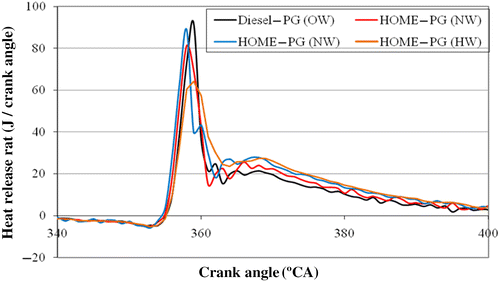
Figure shows the rate of heat release versus CA for the different HOME–producer gas and diesel–producer gas combinations at the 80% load. The results showed that HOME–producer gas derived from the OW, NW and HW results in a lower heat release rate compared with the diesel–producer gas operation, as shown in the figure. This is due to the burning of the fuel combination during the diffusion combustion phase that leads to the second peak compared with the diesel–producer gas operation. The lower calorific value, lower density, low volatile matter and higher ash and lignin contents present in the wood are responsible for the lower heat release rate.
5. Estimation of uncertainty
All experimental data were associated with uncertainties that ultimately limit the conclusions of the present study. Random errors arise from the fluctuations that can result from multiple trials of any given measurement. Systematic errors can be corrected by the periodic calibration of the instruments. The uncertainties of different quantities were estimated and found to be 1.56, 16.68, 3.6, 6.65, 4.25, 12.68 and 3.45% for BTE, EGT, volumetric efficiency, smoke opacity, CO, NOx and fuel substitution, respectively.
6. Conclusions
The following conclusions were made for the present study:
Use of alternative and renewable fuels such as bio-diesels derived from non-edible oils and producer gas derived from biomass for engine applications avoids the conflict between food and energy security. The Honge, neem and babul trees being locally and abundantly available in the region can provide sustained energy resources for the biomass-based energy generation.
Operation of the HOME and producer gas gasifier–engine system with optimum engine parameters makes the system completely independent from fossil fuel. The HOME–producer gas operation under a dual-fuel mode does not require any major engine modifications.
Utilization of woody biomass proves to be a very promising alternative biomass feedstock with compromising efficiency. The efficiency of HOME–producer gas derived from the HW was found to be lower than the efficiency of those derived from the other woody biomass feed stock tested.
On an average, at optimum operating conditions and at the 80% load, the HOME–producer gas (OW) operation resulted in an increase in BTE of 16.1 and 29.6% compared with the operation of HOME–producer gas derived from the NW and HW, respectively.
Smoke opacity was reduced by 8.1 and 20.2% for the HOME–producer gas (OW) operation compared with the HOME–producer gas operation with the NW and HW, respectively. For the HOME-producer gas (OW) operation, smoke opacity was reduced by 8.1 and 20.2 % compared to HOME–producer gas (NW) and HOME–producer gas (HW) operation respectively. Similarly, for the HOME–producer gas (OW) operation, HC emission levels were reduced by 7.4 and 16.1% and CO emission levels were reduced by 19.1 and 26.1% compared to HOME–producer gas (NW) and HOME–producer gas (HW) operation at 80% load.
At the 80% load, the maximum peak pressure obtained for the HOME–producer gas (OW) operation was 55.6 bar compared with 52.5 and 49.8 bar for the HOME–producer gas operation with the NW and HW, respectively.
The percentage of fuel substitution for the HOME–producer gas (OW) operation was 51% compared with 46 and 41% for the operation of HOME–producer gas derived from the NW and HW, respectively, at the 80% load.
Improvements in performance can be obtained by the method of turbo-charging, advanced injection timing, higher injection pressure, the use of a higher compression ratio and the addition of hydrogen in the producer gas.
References
- Alptekin, Ertan, and MustafaCanakci. 2009. “Characterization of the Key Fuel Properties of Methyl Ester–Diesel Fuel Blends.” Fuel88 (1): 75–80.
- Anil, T. R., S. D.Ravi, M.Shashikanth, N. K. S.Rajan, and P. G.Tewari. 2006. “CFD Analysis of a Mixture Flow in a Producer Gas Carburetor.” In International Conference on Computational Fluid Dynamics, Acoustics, Heat Transfer and Electro-magnetics (CFEMATCON-06). Andhra University, Visakhapatnam, India, July 24–25.
- Anjireddy, B., and R. C.Sastry. 2011. “Biomass Gasification Processes in Downdraft Fixed Bed Reactors: A Review.” International Journal of Chemical Engineering and Applications2 (6): 425–433.
- Asri, Gani, and NaruseIchiro. 2007. “Effect of Cellulose and Lignin Content on Pyrolysis and Combustion Characteristics for Several Types of Biomass.” Renewable Energy32: 649–661.
- Awasthi, Mamta, and Rani DeepikaKarishma. 2013. “Energy Through Agricultural Residues in Rural India: Potential, Status and Problems.” International Journal of Emerging Technology and Advanced Engineering3 (3): 160–166.
- Azzoni, P., G.Minelli, and D.Moro. 1999. “Air–Fuel Ratio Control for a High Performance Engine Using Throttle Angle Information.” Society of Automotive Engineers, USA. Paper 1999-011169.
- Banapurmath, N. R., and P. G.Tewari. 2009. “Comparative Performance Studies of a 4-Stroke CI Engine Operated on Dual Fuel Mode with Producer Gas and Honge Oil and Its Methyl Ester (HOME) With and Without Carburetor.” Renewable Energy34: 1009–1015.
- Banapurmath, N. R., P. G.Tewari, Y. H.Basavarajappa, and V. S.Yaliwal. 2005. “Performance of Honge (Pongamia pinnata) Oil Blends in a Diesel Engine.” In XIX NCICEC, Annamalai University, Chidambaram, India1–6.
- Banapurmath, N. R., P. G.Tewari, and R. S.Hosmath. 2008. “Performance and Emission Characteristics of Direct Injection Compression Ignition Engine Operated on Honge, Jatropha and Sesame oil Methyl Ester.” Renewable Energy33: 1982–1988.
- Banapurmath, N. R., P. G.Tewari, V. S.Yaliwal, KambalimathSatish, and Y. H.Basavarajappa. 2009. “Combustion Characteristics of a 4-Stroke CI Engine Operated on Honge Oil, Neem and Rice Bran Oils When Directly Injected and Dual Fuelled with Producer Gas Induction.” Renewable Energy34: 1877–1884.
- Banapurmath, N. R., V. S.Yaliwal, KambalimathSatish, A. M.Hunashyal, and P. G.Tewari. 2011. “Effect of Wood Type and Carburetor on the Performance of Producer Gas–Biodiesel Operated Dual Fuel Engines.” Waste and Biomass Valorization2 (4): 1–11, Springer Publications, ISSN 1877-2641.
- Bhattacharya, S. C., and JanaChinmoy. 2009. “Renewable Energy in India: Historical Developments and Prospects.” Energy34: 981–991.
- Bridgwater, A. V., A. J.Toft, and J. G.Brammer. 2002. “A Techno-Economic Comparison of Power Production by Biomass Fast Pyrolysis with Gasification and Combustion.” Renewable and Sustainable Energy Reviews6 (3): 181–246.
- Canakci, M.2005. “Performance and Emission Characteristics of Biodiesel from Soyabeen oil.” Proc. IMechE. – Part DJournal of Automobile Engineering219: 915–922.
- Churchill, D. B., S. L.Hedden, J. D.Whitney, and L. N.Shaw. 1986. “Chipping Citrus Wood for Gasification, Applied Engineering in Agriculture.” American Society of Agricultural Sciences2 (2): 238–240.
- Dasappa, S., H. V.Sridhar, G.Sridhar, and P. J.Paul. 2011. “Science and Technology Aspects of Bio-residue Gasification.” Biomass Conversion and Biorefinery1: 121–131.
- Demirbas, A.2005. “Biodiesel Production from Vegetable Oils via Catalytic and Non-catalytic Supercritical Methanol Transesterification Methods.” Progress in Energy Combustion and Science31: 466–487.
- DeshmukhS. J., L. B.Bhuyar, and S. B.Thakre. 2008. “Investigation on Performance and Emission Characteristics of CI Engine Fuelled with Producer Gas and Esters of Hingan (Balanites) Oil in Dual Fuel Mode.” International Journal of Mechanical Systems Science and Engineering2 (3): 148–153.
- Evandro, Novaes, KirstMatias, ChiangVincent, Winter-SederoffHeike, and SederoffRonald. 2010. “Lignin and Biomass: A Negative Correlation for Wood Formation and Lignin Content in Trees.” American Society of Plant Biologists154 (2): 555–561. doi:10.1104/pp.110.161281.
- Galik, Christopher S., Robert C.Abt, and YunWu. 2009. “Forest Biomass Supply in the South-Eastern United States – Implications for Industrial Roundwood and Bioenergy Production.” Journal of Forestry107 (2): 69–77.
- Hassan, S., Z. A.Zainal, S.Aizat, and M. A.Miskam. 2011. “The Effects of Supercharging on the Performance and Exhaust Gas Emissions of a Dual-Fuel Engine Fueled with Producer Gas–Diesel and Palm Oil Blends.” Middle-East Journal of Scientific Research7 (2): 162–169. ISSN 1990-9233.
- Jingura, Raphael M., DownmoreMusademba, and RutendoMatengaifa. 2010. “An Evaluation of Utility of Jatropha curcas L. as a Source of Multiple Energy Carriers.” International Journal of Engineering, Science and Technology2 (7): 115–122.
- Jorapur, R. M., and A. K.Rajvanshi. 1993. “Operating Experience and Economics of a 15 kVA Genset–Gasifier System Running on Loose Sugarcane Leaves.” In Recent Advances in Biomass Gasification and Combustion, edited by P. J.Paul and H. S.Mukunda, 257–273. Bangalore: Interline.
- Mark Jan Prins. 2005. “Thermodynamic Analysis of Biomass Gasification and Torrefaction.” In Technische Universiteit Eindhoven, The Netherlands, 1–55. ISBN: 90-386-2886-2. http://alexandria.tue.nl/extra2/200510705.pdf.
- McKendry, P.2002. “Energy Production from Biomass (Part 2): Conversion Technologies.” Bioresource Technology83: 47–54.
- Mehta, Pramod S., and K.Ananda. 2009. “Biodiesel for Engines.” In Proceedings of the 21 National Conference on IC Engines and Combustion, 43–62, BIT Davangere, December 10–12.
- Mihai, Brebu, and VasileCornelia. 2010. “Thermal Degradation of Lignin – A Review.” Cellulose Chemistry and Technology44 (9): 353–363.
- Mohod, A. G., S. R.Gadge, and V. N.Mandasure. 2003. “Liberation of Carbon Monoxide Through Gasifier I.C. Engine System.” I.E. (I) Journal I.D.84: 27–29.
- Muralidharan, K., D.Vasudevan. 2011. “Performance, Emission and Combustion Characteristics of a Variable Compression Ratio Engine using Methyl Esters of Waste Cooking Oil and Diesel Blends.” Applied Energy88(11): 3959–3968.
- Murugesan, A., C.Umarani, R.Subramanian, and N.Nedunchezhian. 2009. “Bio-diesel as an Alternative Fuel for Diesel Engines—A Review.” Renewable and Sustainable Energy Reviews13 (3): 653–662.
- Naik, Satyanarayan, Vaibhav V.Goud, Prasant K.Rout, KathleneJacobson, and Ajay K.Dalai. 2010. “Characterization of Canadian Biomass for Alternative Renewable Biofuel.” Renewable Energy35: 1624–1631.
- Nouni, M. R., S. C.Mullick, and T. C.Kandpal. 2007. “Biomass Gasifier Projects for Decentralized Power Supply in India: A Financial Evaluation.” Energy Policy35: 1373–1385.
- Ohyama, Y.1999. “Air–Fuel Ratio Control Using Upstream Models in the Intake System.” Society of Automotive Engineers. Paper 1999-0857.
- Panwar, N. L.2011. “Performance of Open Core Down Draft Gasifier with Densified Agro Residue Fuel.” International Journal of Sustainable Energy30 (5) : doi:https://doi.org/10.1080/1478646X.2010.509505.
- Panwar, N. L., KothariRicha, and V. V.Tyagi. 2012. “Thermo Chemical Conversion of Biomass – Eco Friendly Energy Routes.” Renewable and Sustainable Energy Reviews16 (4): 1801–1816.
- Panwar, N. L., N. S.Rathore, and A. K.Kurchania. 2009. “Experimental Investigation of Open Core Downdraft Biomass Gasifier for Food Processing Industry.” Mitigation and Adaptation Strategies for Global Change14 (6): 547–555.
- Parikh, P. P., A. G.Bhave, and D. V.Kapse. 1989. “Shashikantha, Study of Thermal and Emission Performance of Small Gasifier–Dual-Fuel Engine Systems.” Biomass19: 75–97.
- Pasangulapati, V., K. D.Ramachandriya, A.Kumar, M. R.Wilkins, C. L.Jones, and R. L.Huhnke. 2012. “Effects of Cellulose, Hemicellulose and Lignin on Thermochemical Conversion Characteristics of the Selected Biomass.” Bioresource Technology114: 663–669. 10.1016/j.biortech.2012.03.036.
- Pratik, N. S., and B. V.Babu. 2009. “Experimental Studies on Producer Gas Generation from Wood Waste in a Downdraft Biomass Gasifier.” Bioresource Technology100: 3127–3133.
- Raheman, H., and S. V.Ghadge. 2008. “Performance of Diesel Engine with Biodiesel at Varying Compression Ratio and Ignition Timing,” Fuel87: 2659–2666.
- Ramadas, A. S., S.Jayaraj, and C.Muraleedharan. 2006. “Power Generation Using Coir Pith and Wood Derived Producer Gas in a Diesel Engine.” Fuel Processing Technology87: 849–853.
- Ramadas, A. S., S.Jayaraj, and C.Muraleedharan. 2008. “Dual Fuel Mode Operation in Diesel Engines Using Renewable Fuels; Rubber Seed Oil and Coir Pith Producer Gas.” Renewable Energy339: 2077–2083.
- Rathore, N. S., N. L.Panwar, and Y.Vijay Chiplunkar. 2008. “Design and Techno Economic Evaluation of Biomass Gasifier for Industrial Thermal Applications.” African Journal of Environmental Science and Technology3 (1): 6–12. ISSN 1991-637X.
- Ravindranath, N. H., and P.Balachandra. 2009. “Sustainable Bioenergy for India: Technical, Economic and Policy Analysis.” Energy34: 1003–1013.
- Roy, M. M., TomitaEiji, KawaharaNobuyuki, HaradaYuji, and SakaneAtsushi. 2009. “Performance and Emission Comparison of a Supercharged Dual-Fuel Engine Fueled by Producer Gases with Varying Hydrogen Content.” International Journal of Hydrogen Energy34: 7811–7822.
- Sahoo, P. K., L. M.Das, M. K. G.Babu, P.Arora, V. P.Singh, N. R.Kumar, and T. S.Varyani. 2009. “Comparative Evaluation of Performance and Emission Characteristics of Jatropha, Karanja and Polanga Based Biodiesel as Fuel in a Tractor Engine.” Fuel88 (9): 1170–1698.
- Sahoo, B. B., U. K.Saha, and N. Sahoo. 2011. “Theoretical Performance Limits of a Syngas-diesel Fueled Compression Ignition Engine from Second Law Analysis.” Energy36: 760–769.
- Sahoo, B. B., N.Sahoo, and U. K.Saha. 2009. “Effect of Engine Parameters and Type of Gaseous Fuel on the Performance of Dual-Fuel Gas Diesel Engines—A Critical Review.” Renewable and Sustainable Energy Reviews13: 1151–1184.
- Samir, J. D., B. B.Lalit, and B. T.Shashikant. 2008. “Investigation on Performance and Emission Characteristics of CI Engine Fuelled with Producer Gas and Esters of Hingan (Balanites) Oil in Dual Fuel Mode.” International Journal of Mechanical Systems Science and Engineering2 (3): 148–153.
- Sayin, Cenk, and MetinGumus. 2011. “Impact of Compression Ratio and Injection Parameters on the Performance and Emissions of a DI Diesel Engine Fueled with Biodiesel-blended Diesel Fuel.” Applied Thermal Engineering31: 3182–3188.
- Scragg, A. H., J.Morrison, and S. W.Shales. 2003. “The Use of a Fuel Containing Chlorella Vulgaris in a Diesel Engine.” Enzyme and Microbial Technology33 (7): 884–888.
- Singh, R. N., S. P.Singh, and B. S.Pathak. 2007. “Investigations on Operation of CI Engine Using Producer Gas and Rice Bran Oil in Mixed Fuel Mode.” Renewable Energy32: 1565–1580.
- Sridhar, G., H. V.Sridhar, S.Dasappa, P. J.Paul, N. K. S.Rajan, and H. S.Mukunda. 2005. “Development of Producer Gas Engines.” Part D: Proc. IMechEJournal of Automobile Engineering219: 423–437.
- Tseng, T. C., and W. K.Cheng. 1999. “An Adaptive Air/Fuel Ratio Controller for SI Engine Throttle Transients.” Massachusetts Institute of Technology, 1999-01-0552.
- Uma, R., T. C.Kandpal, and V. V. N.Kishore. 2004. “Emission Characteristics of an Electricity Generation System in Diesel Alone and Dual Fuel Modes.” Biomass and Bioenergy27: 195–203.
- Zhang, Hongmei, and JunWang. 2007. “Oil from Biomass Corncob Tar as a Fuel.” Energy Conversion and Management—Bioresource Technology48: 1751–1757.

