Abstract
The aim of this paper is to develop computational machining energy estimation tools during the early design stage of product development. In the preliminary or embodiment design, a product's shape and materials are determined. At this stage, it is crucial for a designer to be able to compare alternative designs and materials based on many different criteria, such as cost, functionality, energy, etc. Automated tools for estimating energy consumption that could later be used to integrate with CAD/CAM systems are in demand. This study presents computational tools for estimating the energy consumption of machining operations during the early design phase. The computational tools utilize a preliminary computer representation of a product (CAD model), its material and candidate machining operations to automatically analyse and estimate a range of energy consumption during machining operations. Detailed steps for computing turning and milling energy consumption are presented. Case studies of both parts and assemblies were conducted to test the validity of the tools and to evaluate the performance of the tools. Environmental impacts such as carbon weight will also be estimated. The computation tools will assist users with little knowledge about energy computations to estimate energy consumption during the design stage. Such energy estimation can be used to redesign parts and assemblies, leading to the development of products with reduced machining energy. The computation tools are part of a larger research on estimating energy consumption throughout a product's life cycle.
Keywords::
1. Introduction
Excessive energy consumption may result in (1) increasing net greenhouse gas emissions and (2) increasing acid deposition and air pollution [T. Orr, “Simple Energy Solutions Help Save an Ailing Environment” (Daily Nexus, 88(40), http://dailynexus.com/2007-11-20/simple-energy-solutions-help-save-an-ailing-environment/)]. Greenhouse gas emissions result in global warming and global climate problems. Nitrogen oxides, sulphur dioxide and mercury compounds that are emitted into the air can significantly reduce air quality and threaten human health. Excessive energy consumption involves a direct cost of increased energy bills and an added cost of dealing with emissions and pollutions. Therefore, it increases the total cost of products.
Excessive energy consumption is a pressing issue in today's design and manufacturing industry (MIT Citation2012; Global Green House Warming Citation2012). Manufacturers have the responsibility to manufacture products energy-efficiently and also emit low greenhouse gases. According to a well-known engineering design text book (Ulrich and Eppinger Citation2008), ‘approximately 70% of a product's cost is determined in the design stage. This will imply costs of material, manufacturing, transportation, etc., including the energy costs.’ Therefore, in order to produce energy-efficient products, product designers have to design the product for energy efficiency. It is vital to reduce energy consumption at the design stage. Currently, there are various tools such as Solidworks and Pro/E (Solidworks Citation2012; PTC Citation2012) for modelling a product's shape, materials and manufacturing processes. However, to the best of the authors' knowledge, estimating energy consumption during the design stage is one area that has been given little attention.
The above literature emphasizes the idea of sustainability and gives inspirations to develop software tools to optimize energy consumption. Such tools will help the manufacturing industry to achieve a sustainable strategy in order to minimize environmental impacts and costs. Specifically, the focus of this paper is to aid the designer to estimate energy consumption during the early design stage at which mostly a product's shape and materials are determined. Before the determination of specific details of a manufacturing process, a designer can benefit from energy estimation between two or more candidate designs or manufacturing processes. Prior to probing into the details of the tools, several concepts need to be introduced. Section 2 presents the relevant literature review on energy efficiency and current modelling tools and frameworks for sustainable manufacturing, indicating the significance of developing such tools. Section 3 presents the overall approach for energy estimation followed by Sections 4 and 5 that present the algorithms for milling and turning energy estimations, respectively.
2. Literature review
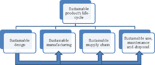
The life cycle of a sustainable product is an umbrella concept that covers different stages of a product's life cycle, including sustainable design and manufacturing. This is depicted in Figure . Product design includes the planning for shape and materials and a high-level planning for manufacturing, supply chain, product use, maintenance and disposal. Sustainable design will ensure that the planning of the other stages of a product's life cycle is sustainable. Later during the manufacturing stage, details can be further worked out to ensure that manufacturing or disposal is sustainable. Decisions taken during the design stage affect all the other stages. Feedback from the other stages can be incorporated during the design stage usually for the next generation of products.
Environmental impacts (Ameta et al. Citation2011), as one aspect of sustainability, are measured by life-cycle assessment (LCA). LCA can be used at the end of design or manufacturing. One of the sources of environmental impacts is energy consumption throughout a product's life cycle. The literature presented in this section discusses sustainable manufacturing, LCA, energy estimation and related tools.
2.1 Sustainable manufacturing
Sustainable manufacturing has become a strategic trend in the manufacturing industry. According to the US Department of Commerce, sustainable manufacturing is defined as ‘the creation of manufactured products that use processes that are non-polluting, conserve energy and natural resources, and are economically sound and safe for employees, communities, and consumers’ (DOC Citation2009). According to Reich-Weiser et al. (Citation2008), three important components of a sustainable manufacturing strategy are (1) selection and application of appropriate modelling metrics for measuring manufacturing sustainability, (2) completion of comprehensive, transparent and repeatable LCA and (3) adjustment/optimization of the system to minimize environmental impacts and costs.
2.2 Life-cycle assessment
According to Khan, Sadiq, and Husain (Citation2002), LCA is one of the most important techniques for the successful implementation of a process or product development in the context of environmental sustainability. The methodological framework for LCA is defined by the ISO 14040 series, which includes goal and scope definition, inventory analysis, impact assessment and interpretation (ISO Citation2006). Rebitzer et al. (Citation2004) reviewed the framework, goal and scope definition, inventory analysis and applications of LCA. Due to the importance of LCA during the process of product development, LCA has been applied in various aspects such as product design and manufacturing. Bevilacqua, Ciarapica, and Giacchetta (Citation2007) developed a life-cycle model of a sustainable product by combining environmental and economic considerations in manufacturing firms. Many research projects have integrated LCA with CAD for users to apply decisions at the design stage. Nawata and Aoyama (Citation2006) developed a life-cycle design system for machine tools by linking LCA data to CAD/CAM data. Leibrecht (Citation2005) discussed basic principles for integrating LCAs into a CAD-based product model.
Despite the large application of LCA, it has its disadvantages (Reap et al. Citation2008a, Citation2008b). Moreover, LCA provides only methodology for assessing the environmental impacts and does not provide any tools or metrics for reducing the impacts (Leibrecht Citation2005).
2.3 Energy efficiency and energy implication
Energy is expected to sustain every aspect of a product's life cycle: material production, manufacturing, supply chain, use, maintenance and end of the life of the product. A study conducted by the National Association of Manufacturers has speculated a possible savings of about 19 billion dollars with development of new energy-efficient technologies (Russell Citation2004). The Energy Star (EnergyStar Citation1992) standard has been developed in an attempt to reduce use-phase energy consumption. However, Energy Star does not include energy consumption during the manufacturing phase of a product's life cycle.
Extensive research has been conducted to utilize energy efficiently during manufacturing processes. Munoz and Sheng (Citation1995) found an analytical approach to determine the environmental impact of machining. Sheng, Bennet, and Thurwachter (Citation1998) investigated an environmental-based systems planning for machining. However, the research focused on energy consumption in the process of material removal only. Chen et al. (Citation2008) created a new life-cycle energy-consuming model to estimate energy consumption during the entire product's life cycle. Gutowski and co-workers' investigated various energy impacts of different manufacturing processes and conducted an environmental analysis of machining (Gutowski, Dahmus, and Dalquist Citation2005; Gutowski, Dahmus, and Thiriez Citation2006, Gutowski et al. Citation2007), generalizing the energy consumption of diverse manufacturing processes. Jeswiet and Kara (Citation2008) generalized the computation of CO2 factors from electricity requirements for product-related CO2 emissions. However, the authors did not consider the variability of manufacturing processes. Ameta et al. (Citation2009) presented specific case studies on machining energy and CO2 factors. In those studies, machining energy at the design stage was computed manually with no discussion on automation tools.
2.4 Relevant modelling tools and frameworks
Currently, a large number of modelling tools are available, which are in use in the sustainable manufacturing industry. Zhao and Shah (Citation2004) conducted research on the modelling and representation of manufacturing knowledge for Design for Manufacturing (DfM) systems to help engineers to formulize their manufacturing knowledge and store it in a computer, and help the designers analyse manufacturability during the design stage. However, the researchers either concentrated on a specific domain of manufacturing or paid attention only to a particular phase of a product's life cycle. Therefore, constructing a generic domain-independent framework for the entire product's life cycle is in demand.
Numerous researchers have proposed diverse frameworks for sustainable manufacturing. Ou-Yang and Lin (Citation1997) developed an integrated framework for feature-based early manufacturing cost estimation. This system tends to provide a tool to assist designers to estimate the cost during the design stage in order to downstream any unnecessary costs. Shin and Waters (Citation1998) developed a framework for a machining advisory system that could combine the rules for inferring optimal machining parameters. Lee et al. (Citation1998) presented a computational framework for supporting the concurrent mould manufacturing process planning. The present study facilitates the automation of the mould development process planning, thus improving the efficiency and quality of the moulding product. Wei and Egbelu (Citation2000) proposed a framework for estimating the manufacturing cost from geometric design data. Kwon, Chung, and Pentland (Citation2002) developed a grammar-based framework for integrating design and manufacturing. It helps engineers to navigate through the process alternatives and to foresee the effects of different design choices. Zhao and Shah (Citation2002, Citation2005) developed a normative DfM framework based on benefit–cost analysis to deal with the trade-offs between design objectives and manufacturing cost/efficiency. Yang and Lee (Citation1998) proposed a feature modification framework for the generation of alternative process plans. A brief summary of the reviewed literature is illustrated in Table .
Table 1 Summary of the literature review.
These research efforts have shown a significant progress in the areas of sustainable manufacturing. However, none of these frameworks can be directly utilized for energy estimation.
To digitally integrate frameworks and models into an enterprise's product development process, the integration of LCA with CAD/CAM systems is of interest. There are a lot of existing LCA software products, such as SimaPro (2012, http://www.pre-sustainability.com/simapro-lca-software), Ecoscan (Citation2012) and GaBi (Citation2012), allowing LCAs at a high level of details. However, to the authors' knowledge, none of the approaches can help designers to estimate energy consumption. Therefore, the focus of this study is to develop a framework to support a sustainable product's life cycle. For this purpose, the 'current focus is on the development of a framework to support energy estimation. One part of this framework, and the focus of this study, is on the development of machining energy estimation tools at the design stage based on a high level of manufacturing information, such as geometry, materials and basic process. For a discussion on the development of energy estimation tools for machining from specific machining parameters, refer to previously published studies (Tharakan, Zhao, and Shah Citation2003; Turaga, Rachuri, and Roy Citation2011; Li and Kara Citation2011; Kara and Li Citation2011; Avram and Xirouchakis Citation2011; Diaz, Redelsheimer, and Dornfield Citation2011; Huang Citation2012).
3. Goals and approaches for machining energy estimation
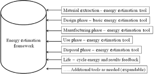
The goal of designing such estimation tools is to help users to estimate energy consumption. Such tools can be attached to an expandable energy estimation framework for calculating energy consumption during a product's life cycle, i.e. from the extraction of raw materials, design and manufacturing, use, to recycling or disposal phases. This paper discusses only the development of tools at the design phase as shown in Figure . The details of developing other estimation tools that are listed in Figure and further integration of estimation tools and the framework have been discussed elsewhere (Huang Citation2012).
The boundaries for machining energy estimation during the design phase are defined as follows:
The estimation tools developed in this paper are limited to the design phase only. Actual energy consumption can be calculated only after the determination of detailed process plans such as manufacturing location and manufacturing equipment. It is impossible to obtain all the manufacturing information during the design stage. Therefore, a range of uncertainties for energy estimation exist, and the refinement of the results is related to the detailed process plans. The estimation for detailed process plans will be considered in future work.
The focus of this paper is on machining operations, specifically the development of milling and turning energy estimation tools. Energy estimation tools for other manufacturing processes can be developed with high-level domain knowledge of those manufacturing processes.
Currently, the research focus is on energy estimation through theoretical calculations; inclusion of experimental data and uncertainty accounting is reserved for future work.
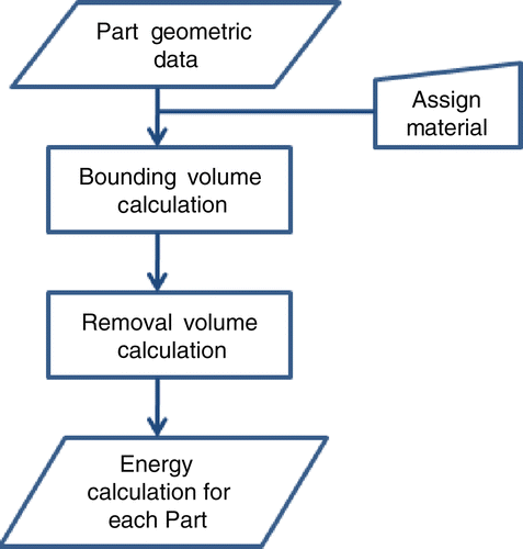
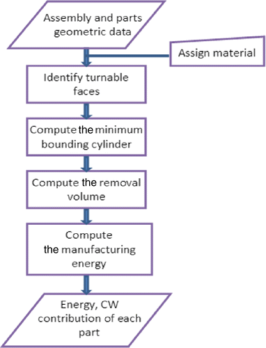
Figure illustrates a general approach to estimating energy consumption for machining a part. Geometric data with assigned material properties are used as the input for calculation. The next step is the computation of the minimum bounding volume for each part. The minimum bounding solid serves as a stock for machining the final part. The methods for computing the minimum bounding volume may vary depending on specific machining operations (e.g. milling and turning in this paper). The next step is to identify the removal volume. The removal volume can be identified by performing Boolean subtraction between each part and stock or the minimum bounding volume. Then, the machining energy for parts can be computed based on the generalized data available from the literature (e.g. Kalpakjian and Schmid Citation2005).
The manufacturing energy of the assembly can be computed as the sum of the manufacturing energies of individual parts and the energy for assembling all the parts together, as shown in Equation (1):
For the purposes of simplifying the calculations, in this paper, assembling energy is assumed to be zero. Although assembling energy is ignored, it can be accounted for by identifying the assembling process, the related time for the given parts and energy for the unit assembling process. By assuming the assembling energy to be zero, Equation (1) simply adds individual energy estimates of each part in manufacturing processes. Transportation energy can only be estimated at the manufacturing stage when specific locations of part production (even within the same facility) are identified. Since the focus is to estimate energy consumption during the early design stage, transportation energy is assumed to be zero. To include uncertainties in energy estimate from a range of stipulated specific energies for machining (Kalpakjian and Schmid Citation2005), the authors proposed the computation of maximum and minimum manufacturing energy, which can be computed as shown in Equations (2) and (3), respectively. The assembly energy in Equations (2) and (3) is merely the addition of the energy estimates of part manufacturing processes:
If a statistical distribution is known for the variations of the specific energy and removal volume, then standard statistical methods can be applied to compute the resultant distribution of energy. The following section presents the computation of milling and turning energy consumption using Equations 12(3). Before using the equations, Section 4 presents the algorithms to compute the amount of materials removed during the milling and turning processes. This information on material removal is used in Equations 12(3) to estimate manufacturing energy.
4. Milling energy computation
4.1 Steps to compute energy estimates
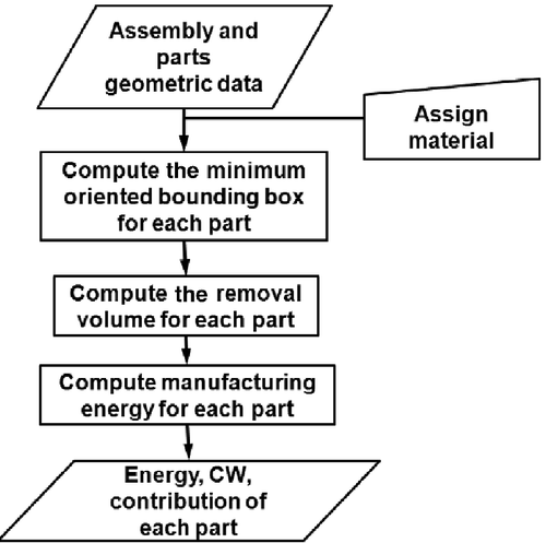
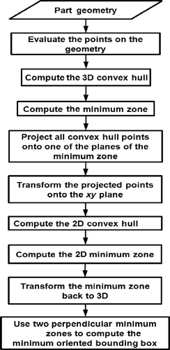
Figure provides the details for computing energy estimates for parts and assemblies based on approaches discussed above. Assembly- or part-level geometric data with assigned material properties are used as the input for computation. To compute the minimum oriented bounding box for each part, it is assumed that this box would serve as a stock for machining the final part. The identification of the minimum oriented bounding box is necessary for the following two reasons: (a) the orientation of a part in an assembly may not be aligned with the coordinate planes; (b) the study aims to automate the computation of the stock. The removal volume can then be identified by performing Boolean subtraction between each part and the respective stock (minimum oriented bounding box). The volume of the resultant geometry from Boolean subtraction will be the removal volume for manufacturing (milling in our case) the part from the computed stock. The machining energy for the part is computed based on the generalized data available from the literature (Kalpakjian and Schmid Citation2005). The machining energy for all the parts is later aggregated to arrive at the overall energy for machining the whole assembly. Information regarding energy-intensive parts is also provided in order to aid an energy-efficient redesign.
4.2 Algorithm for calculating the minimum oriented bounding box
Various researchers have presented algorithms for computing the minimum oriented bounding box (Barequet and Har-Peled Citation2001; Chan and Tan Citation2001). A survey and classification of different kinds of box-fitting algorithms is provided by Ding, Mannan, and Poo (Citation2004) and Dyckhoff (Citation1990). The algorithm presented in this paper takes a novel approach, as it utilizes the minimum zone algorithm used in verifying flatness tolerances during inspection. It must be noted that the comparative efficiency of the proposed algorithm has not been tested yet. The related discussion is beyond the scope of this paper.
Figure presents the algorithm in detail. The first step is to create points on the part geometry. Using these points, a convex hull for the part is computed by qhull (Barber, Dobkin, and Huhdanpaa Citation1996). Utilizing the facets and vertices of the convex hull, a minimum zone is computed using the min–max algorithm. This algorithm generates two parallel planes that are at a minimum distance apart, and all the points of the convex hull lie between them. After obtaining the minimum zone, all the points of the convex hull are projected onto one of the planes of the minimum zone. Then, the plane is transformed to the x–y plane. A 2D convex hull is computed, followed by two minimum zones where the product of the distances is minimized. The 2D minimum zones are then transformed back to their original location, using the inverse transform. Finally, the resultant minimum oriented bounding box is obtained from these three minimum zones.
To test the above algorithm for the minimum oriented bounding box, a revolved part is used (as it does not have planar faces), as shown in Figure (a). The input to the convex hull consists of 2566 vertices on the geometry, while the final convex hull consists of 586 vertices and 1139 facets.
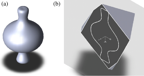
All the vertices of the 3D convex hull are projected onto this plane. The 2D convex hull of these projected vertices consists of 44 vertices and 44 facets (edges) only. Using the 2D convex hull, two perpendicular minimum zones are computed where the product of the distances is minimized. Utilizing the three minimum zones, the minimum oriented bounding box is computed for the given part. Figure (b) shows a cut view of the fitting of the revolved part (Figure (a)) and the computed minimum oriented bounding box.
After the vertices are projected onto 2D, the minimum zone algorithm alone cannot be used. The minimum zone algorithm searches for the smallest distance between two parallel planes within which all the points should lie.
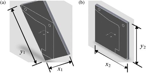
The current algorithm searches two minimum zones with a minimized product of the minimum distances. The example part shown in Figure (a) is used to demonstrate the difference in two algorithms. Figure (b) shows the convex hull generated using qhull. Figure (a),(b) shows the overlap of the resulting bounding box and part from Figure (a). The bounding box in Figure (a) is computed with the minimum zone algorithm. The minimum zone algorithm found x1 and y1 to be the minimum distance between two planes within which lie all the 2D projected points of the part. The bounding box shown in Figure (b) is computed using the minimized product of two minimum distances. The algorithm searches for a minimum value for x × y. This leads to the rectangle with lengths x2 and y2. It is intuitively clear that the minimum oriented bounding box is the one shown in Figure (b).
4.3 Case study
In this paper, the case studies are discussed from two view points: single part and an assembly of parts. Energy and carbon weight (CW) estimation for each case are presented for the preliminary design and detail design. CAD file handling and visualization is created using the ACIS kernel (ACIS Spatial Citation2012).
4.3.1 Single part: cover plate
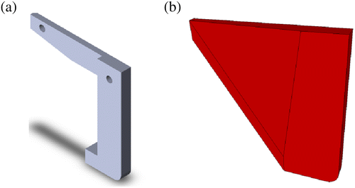
The sample part is a cover plate, as shown in Figure . A shaded view of the cover plate at the preliminary and detail design stages is shown. The only difference between the preliminary and detail design stages are the fillets at the sharp corners of the cover plate. The material of the cover plate is cast iron. The convex hull and the computed minimum oriented bounding box fitting the cover plate are shown in Figure .


Utilizing the machining energy data obtained from a previous study (Kalpakjian and Schmid Citation2005), energy estimates for milling the cover plate can be computed, as shown in Table . The specific energy of cast iron ranges from 1.6 to 5.5 W-s/mm3, which is large due to the manufacturing variations associated with different tools, fixtures, lubricants, machines and operators. According to Hammond and Jones (Citation2011), embodied energy is the sum of the energy required for material production, and the embodied energy is 25 MJ/kg for iron. The CW can be computed from Watt-hour units of energy consumption based on the data obtained from the US Department of Energy (Citation2002). Computations of CW given in Table are performed by assuming Maryland (factor f = 0.62 metric tons/MW-h) as the state in which the manufacturing is being performed. (Different states have different electricity-to-emission ratios based on the fact that electricity is supplied in different states from different sources, such as hydro, nuclear, coal, etc. Furthermore, some of these factors are associated with CO2 emissions.)
Table 2 Comparison of the calculations of the range of energy and CW estimates of the assembly at the preliminary and detail design stages for the cover plate shown in Figure .
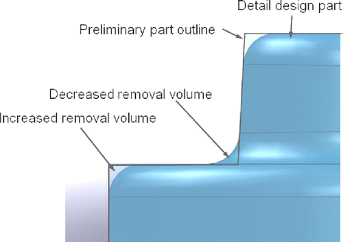
It is evident from the results of the above computation that the addition of the fillets on the cover plate decreased the removal volume for manufacturing the cover plate. The fillets at certain locations increase the removal volume while at other locations, they decrease the removal volume (Figure ). For reducing the energy and CW, the radius of the fillets at the convex corners/edges should be kept as small as possible, while the radius of the fillets at the concave corners/edges should be increased. Since in this simplified case, the fillets are considered as the only difference between the preliminary and detail design stages, suggestions for reducing the energy or CW can only be made based on the geometry of the fillets.
4.3.2 Assembly: slider-crank mechanism
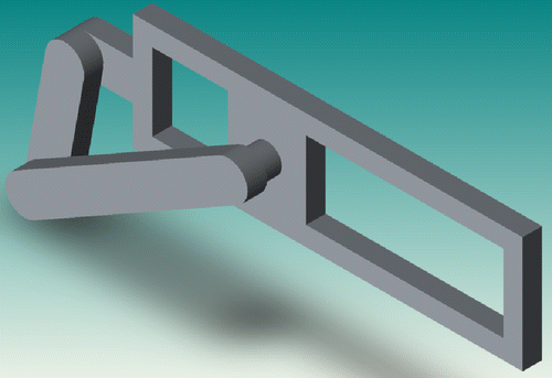
We consider a simplified slider-crank assembly, as shown in Figure . The difference between the preliminary and detail design stages is again at the level of the fillets at the sharp corners of the cover plate. The material for the parts is assumed to be cast iron.
The computation of the removal volume for individual parts is performed in the same manner as described in Section 4.1. After the estimation of a range of machining energy for each part, worst-case and statistical-case energy ranges are computed for the assembly.
For computing the worst-case and statistical-case energy ranges, principles from the tolerance analysis are applied. For further details regarding the tolerancing principles for the worst-case and statistical-case analyses, refer to Evans (Citation1970, Citation1974).
Table shows the calculation in detail. The second column in Table lists the removal volume for each part. The third column provides the range estimate of machining energy for each part of the assembly shown in Figure . For machining energy estimates for the whole assembly, two methods are employed. In the worst-case analysis, the minimum and maximum of the range of machining energy for each part are respectively added together.
Table 3 Comparison of the calculations of the range of energy and CW estimates of the assembly at the preliminary and detail design stages for the slider-crank assembly shown in Figure .
For the statistical-case analysis, one could assume that the energy estimates with respect to the practical machining energy would be accurate within 3σ to 6σ variations. The results for the statistical-case analysis includes the mean (μ) and standard deviation (σ) of the energy estimates for the whole assembly. As has been indicated previously, the mean and standard deviation of the manufacturing energy for the whole assembly, μE-assembly and σE-assembly, can be computed from the mean and standard deviation of the manufacturing energy for the individual parts, μE-part-i and σE-part-i, as shown in Equations (5) and (6), respectively:
From the worst-case analysis, the percentage contributions for the crank, rod, slider and base are found to be 10.63%, 33.79%, 0.49% and 55.06%, respectively. The percentage contribution suggests that any reduction in energy for machining the base will have more impact on the overall energy than for machining the slider. If a 10% reduction in the machining energy is desired, then the crank, rod, slider and base need to be redesigned so that the machining energy reduces by 1.06, 3.37, 0.0 and 5.5%, respectively.
5. Turning energy computation
5.1 Steps to compute energy estimates
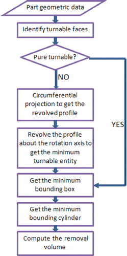
Figure provides the details for computing the energy estimates for parts and assemblies. Assembly- or part-level geometric data with assigned material properties are used as the input for computation. The first step is to identify the turnable faces of parts and assemblies and compute the minimum turnable entities. The identification of a minimum turnable entity is imperative for the following reason: the parts may not be pure turnable and may need other operations such as milling. Therefore, only the turnable removal volume is useful for computing the turning energy. The minimum bounding cylinder is assumed to serve as a stock for machining the final part. The next step is to compute the minimum bounding cylinder for each part and calculate the removal volume. The removal volume can be identified by performing Boolean subtraction between each turnable entity and the respective stock (minimum bounding cylinder). The machining energy for the part is computed based on the generalized data available from the literature (Kalpakjian and Schmid Citation2005).
5.2 Algorithm for calculating the removal volume
Before calculating the removal volume, the turnable and unturnable faces must be determined. If it is a pure turnable part, the removal volume can be directly obtained by subtracting the volume of the part from the minimum bound cylinder. However, in most cases, parts cannot be produced by only using turning operations The algorithm presented in this paper takes a novel approach to automatically recognize the turnable/unturnable faces and calculate a minimum turnable entity that allows a turning machine to fabricate to a large extent. Figure presents the algorithm in detail.
5.3 Computation of minimum turnable entity
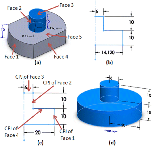
From the step described in the previous section, it has already been determined whether a part is pure turnable or not. If it does have unturnable features, the next step is circumferential projection (CPJ). The concept of CPJ has been proposed to implement this approach (Li and Shah Citation2007). To obtain the CPJ of an entity, all points of the entity are rotated about an axis onto a single plane on which lies the axis, and the union of all these coplanar rotated points is the CPJ of the entity. A study by Li and Shah (Citation2007) illustrates in detail the CPJ of a single point, an edge and a revolved face. A revolving CPJ could return the part to the minimum turnable entity regardless of unturnable faces.
Figure shows an example of a milled/turned part. It should be noted that in this figure, face 4 is unturnable, which means that the part needs to be manufactured by at least two methods, i.e. turning and milling. If one uses a normal projection, there will be some mistakes in calculating the radius of the bounding cylinder. Figure (b) shows the vertical projection of the part. The actual revolved radius is 20 rather than 14.120, which is obtained by the vertical projection. By using CPJ, the actual revolved radius could be found, as shown in Figure (c). After CPJ, the expected profile is obtained; revolving the profile along the rotation axis will build a minimum pure turnable entity. This pure turnable part will be utilized to calculate the minimum bounding box.
5.4 Computation of minimum bounding cylinder
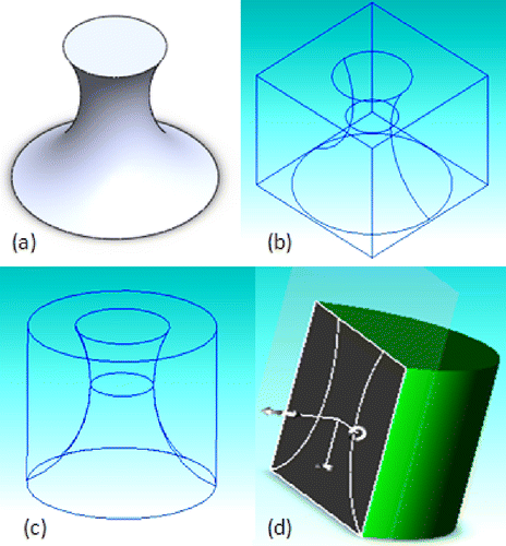
Section 4 presented an algorithm to calculate the minimum oriented bounding box using the minimum zone, convex hull and points transfer from 3D–2D–3D. Using this method, the minimum oriented bounding box can be obtained. Since the bounding box is calculated based on a revolved part (minimum turnable entity), the bounding cylinder can then be easily computed. The removal volume can be determined using Boolean operations. Figure shows the results of calculating the minimum bounding cylinder: Figure (a) is the original turning part and Figure (b) calculates a minimum bounding box and Figure (c),(d) shows the wire frame and cut view of the overlapping of the turning part and its minimum bounding cylinder.
5.5 Case studies
As stated in Section 4.5, the case studies are discussed from two view points: single part and an assembly of parts. Energy and CW estimation for each case is presented for the preliminary design and detail design. It should be noted that we only concentrate on estimating the range of machining energy at the design stage, to assist in choosing a low manufacturing energy design. The actual energy used to manufacture the parts based on tool types, coolant, temperature, fixture, set-ups and idling energy will be included in the future. CAD file handling and visualization is created using the ACIS kernel.
5.5.1 Single part
The sample is a milled/turned mixed part, as shown in Figure . It has four unturnable slots that need to be produced by the milling operation. Both the shaded and wireframe of the part at the preliminary and detail design stages are shown in Figure .
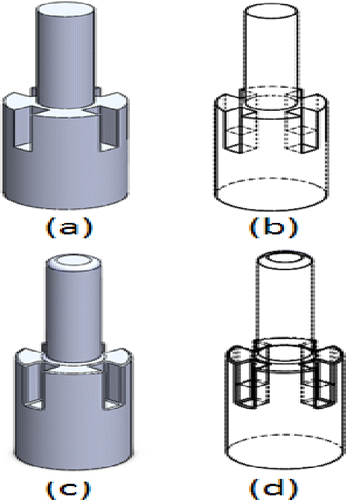
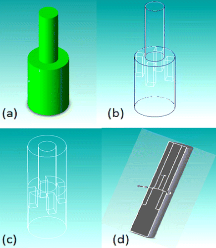
The material of this part is cast iron. Processes for computing the removal volume of the material are shown in Figure . Figure (a),(b) shows the results of computing the minimum turnable entity after implementing the CPJ. Figure (c),(d) shows the results of computing its minimum bounding cylinder.
Utilizing the machining energy data obtained from the literature (Kalpakjian and Schmid Citation2005), as in Section 4.3.1, the energy estimates for turning the part can be computed, as shown in Table . The specific energy for cast iron ranges from 1.6 to 5.5 W-s/mm3. According to a report from the University of Bath (2012), the embodied energy for iron is 25 MJ/kg. The CW can be computed from Watt-hour units of energy consumption based on the data from the US Department of Energy (Update State-level Greenhouse Gas Emission 2002). Computations of CW given in Table are performed by assuming Maryland (factor f = 0.62 metric tons/MW-h) as the state in which the manufacturing is being performed.
Table 4 Comparison of the range of energy and CW estimates of the part at the preliminary and detail design stages for the part shown in Figure (a).
From the results of the computation, the estimation of energy consumption and CW is made at the early design stage. Decisions regarding energy saving and pollution reduction could then be made. It is evident that the addition of the fillets on the part has decreased the removal volume for manufacturing. The fillets at certain locations increase the removal volume while at other locations, they decrease the removal volume. For reducing the energy and CW, the radius of the fillets at the convex corners/edges should be kept as small as possible, while the radius of the fillets at the concave corners/edges should be increased. Since in this simplified case, we considered the fillets as the only difference between the preliminary and detail design stages, and hence suggestions for reducing energy or CW can only be made based on the geometry of the fillets.
5.5.2 Assembly
We consider a simplified assembly as shown in Figure . The computation of the removal volume for the individual parts is performed as described in Section 5.1. The difference between the preliminary and detail design stages are again at the level of the fillets at the sharp corners of the cover plate. The material for the parts is assumed to be cast iron. After the estimation of the range of machining energy for each part, worst-case and statistical-case energy ranges are computed for the assembly.
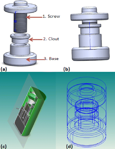
Table shows the calculation in detail. The second column in Table lists the removal volume for each part. The third column provides the range estimate of machining energy for each part of the assembly shown in Figure .
Table 5 Comparison of the calculations of the range of energy and CW estimates of the assembly at the preliminary and detail design stages for the assembly shown in Figure .
For machining the energy estimates for the whole assembly, two methods are employed. In the worst-case analysis, the minimum and maximum of the range of machining energy for each part are respectively added together. Similarly, for the statistical-case analysis, it is assumed that the range of energy estimates would be accurate with 6σ variations with respect to the practical machining energy. The results for the statistical-case analysis includes the mean (μ) and standard deviation (σ) of the range of energy estimates for the whole assembly. Computations related to CW are also shown in column 4 of Table . From the worst-case analysis, the percentage contributions for the screw, clout and base are 74.6%, 5.2% and 24.2%, respectively. The percent contribution suggests that any reduction in energy for machining the screw will have more impact on the overall energy. If a 10% reduction in the machining energy is desired, then the screw, clout and base need to be redesigned so that the machining energy reduces by 7.46%, 0.52% and 2.43%, respectively.
6. Conclusion and future work
In this paper, computational tools for estimating machining energy for parts and assemblies during the design phase were developed. By using these tools, machining energy consumption and environmental impacts such as CW can be estimated.
To compute machining energy, algorithms were presented to automate the process of identifying the removal volume for machining operations for a given part. We subsequently used the identified removal volume together with the material-specific data to compute an energy range for manufacturing the part. Two simplified case studies were presented to demonstrate the approach. We also explored and demonstrated the application of statistical analysis and allocation principles to identify energy-intensive parts/features based on the percent age contribution, thereby assisting the redesign strategies. Such preliminary energy estimates are useful for comparing multiple designs with different shapes, materials or processes. A designer can benefit from the computation of other metrics such as material usage and costs, although they are not included in the present analysis. The tools presented in this paper are developed for milled and turned parts and assemblies, but it can also be extended to other manufacturing methods.
Acknowledgements
The authors thank the anonymous reviewers for their useful comments that aided in improving the quality of the paper.
REFERENCES
- ACIS Spatial. 2012. “3D Modeling Components and Solid Modeler | Spatial.” http://www.spatial.com/products/3d-acis-modeling.
- Ameta, G., M.Mani, S.Rachuri, S. C.Feng, R. D.Sriram, and K. W.Lyons. 2009. “Carbon Weight Analysis for Machining Operation and Allocation for Redesign.” International Journal of Sustainable Engineering2 (4): 241–251.
- Ameta, G., S.Rachuri, X.Fiorentini, M.Mani, S. J.Fenves, K. W.Lyons, and D.Sriram. 2011. “Extending the Notion of Quality from Physical Metrology to Information and Sustainability.” Journal of Intelligent Manufacturing22 (5): 737–750.
- Avram, O. I., and P.Xirouchakis. 2011. “Evaluating the Use Phase Energy Requirements of a Machine Tool System.” Journal of Cleaner Production19 (6–7): 699–711.
- Barber, C. B., D. P.Dobkin, and H.Huhdanpaa. 1996. “The Quickhull Algorithm for Convex Hulls.” ACM Transactions on Mathematical Software (TOMS)22 (4): 469–483.
- Barequet, G., and S.Har-Peled. 2001. “Efficiently Approximating the Minimum-Volume Bounding Box of a Point Set in Three Dimensions.” Journal of Algorithms38 (1): 91–109.
- Bevilacqua, M., F. E.Ciarapica, and G.Giacchetta. 2007. “Development of a Sustainable Product Lifecycle in Manufacturing Firms: A Case Study.” International Journal of Production Research45 (18–19): 4073–4098.
- Chan, C. K., and S. T.Tan. 2001. “Determination of the Minimum Bounding Box of an Arbitrary Solid: An Iterative Approach.” Computers and Structures79 (15): 1433–1449.
- Chen, P., G.Liu, Z.Liu, S.Bian, and Q.Ke. 2008. “Researches on Life Cycle Energy Analysis Method for Mechanic Products.” In Proceedings of the 15th CIRP International Conference on Life Cycle Engineering, New South Wales, Australia, 326–331. ISBN: 1877040673.
- Diaz, N., E.Redelsheimer, and D.Dornfeld. 2011. “Energy Consumption Characterization and Reduction Strategies for Milling Machine Tool Use.” In Glocalized Solutions for Sustainability in Manufacturing, 263–267. Berlin/Heidelberg: Springer.
- Ding, S., M. A.Mannan, and N.Poo. 2004. “Oriented Bounding Box and Octree Based Global Interference Detection in 5-Axis Machining of Free-Form Surfaces.” Computer-Aided Design36 (13): 1281–1294.
- DOC (Department of Commerce). 2009. “How Does Commerce Define Sustainable Manufacturing.” http://www.trade.gov/competitiveness/sustainablemanufacturing/how_doc_defines_SM.asp.
- Dyckhoff, H.1990. “A Typology of Cutting and Packing Problems.” European Journal of Operational Research44 (2): 145–159.
- Ecoscan. 2012. “EUROPA-Site on LCA Tools, Services and Data.” http://lca.jrc.ec.europa.eu/lcainfohub/tool2.vm?tid = 235.
- EnergyStar. 1992. “History: ENERGY STAR.” http://www.energystar.gov/.
- Evans, D. H.1970. “A Statistical Tolerancing Formulation.” Journal of Quality Technology2 (4): 226–231.
- Evans, D. H.1974. “Statistical Tolerancing: The State of the Art. Part I. Background.” Journal of Quality Technology6 (4): 188–195.
- GaBi. 2012. “Gabi Software: Product Sustainability Software.” http://www.gabi-software.com.
- Global Green House Warming. 2012. “Industry CO2 Emissions.” http://www.global-greenhouse-warming.com/industry-CO2-emissions.html.
- Gutowski, T., J.Dahmus, and S.Dalquist. 2005. Measuring the Environmental Load of Manufacturing Processes. Stockholm: International Society for Industrial Ecology (ISIE).
- Gutowski, T., J.Dahmus, and A.Thiriez. 2006. “Electrical Energy Requirements for Manufacturing Processes.” In 13th CIRP International Conference on Life Cycle Engineering, Leuven, Belgium623–638.
- Gutowski, T., J. Dahmus, A. Thiriez, M. Branham, and A. Jones. 2007. “A Thermodynamic Characterization of Manufacturing Processes.” Proceedings of the 2007 IEEE International Symposium on Electronics and the Environment, Orlando, FL, May 7–10.
- Hammond, G., and C. Jones. 2011. “Inventory of Carbon and Energy (ICE) Version 2.0.” University of Bath. http://www.siegelstrain.com/site/pdf/ICE-v2.0-summary-tables.pdf.
- Huang, H.2012. “A CAD-Based Software Framework for Estimating Energy Through a Product Lifecycle.” PhD diss., Washington State University.
- ISO (International Standards Organization). 2006. “ISO 14040:2006 – Environmental Management – Life Cycle Assessment – Principles and Framework.” http://www.iso.org/iso/catalogue_detail?csnumber = 37456.
- Jeswiet, J., and S.Kara. 2008. “Carbon Emissions and CES™ in Manufacturing.” CIRP Annals – Manufacturing Technology57 (1): 17–20.
- Kalpakjian, S., and S.Schmid. 2005. Manufacturing Engineering and Technology. Upper Saddle River, NJ: Pearson Prentice Hall.
- Kara, S., and W.Li. 2011. “Unit Process Energy Consumption Models for Material Removal Processes.” CIRP Annals Manufacturing Technology60 (1): 37–40.
- Khan, F. I., R.Sadiq, and T.Husain. 2002. “GreenPro-I: A Risk-Based Life Cycle Assessment and Decision-Making Methodology for Process Plant Design.” Journal of Environmental Modeling and Software17 (8): 669–692.
- Kwon, P., M. J.Chung, and B.Pentland. 2002. “A Grammar-Based Framework for Integrating Design and Manufacturing.” Journal of Manufacturing Science and Engineering124 (4): 899–907.
- Lee, R., Y.Chen, H.Cheng, and M.Kuo. 1998. “A Framework of a Concurrent Process Planning System for Mold Manufacturing.” Computer Integrated Manufacturing Systems11 (3): 171–190.
- Leibrecht, S.2005. “Fundamental Principles for CAD-Based Ecological Assessment.” International Journal of Life Cycle Assessment10 (6): 436–444.
- Li, W., and S.Kara. 2011. “An Empirical Model for Predicting Energy Consumption of Manufacturing Processes.” Proceedings of the Institution of Mechanical Engineers, Part B: Journal of Engineering Manufacture225 (9): 1636–1646.
- Li, S., and J. J.Shah. 2007. “Recognition of User-Defined Turning Features for Mill/Turn Parts.” Journal of Computing and Information Science in Engineering7 (3): 225–235.
- MIT (Massachusetts Institute of Technology). 2012. “Energy Consumption Trend.” http://www.eecs.mit.edu/eecsenergy/.
- Munoz, A. A., and P.Sheng. 1995. “An Analytical Approach for Determining the Environmental Impact of Machining.” Journal of Materials Processing Technology53 (4): 736–758.
- Nawata, S., and T. Aoyama. 2006. “Development of Life Cycle Design System for Machine Tools-Linkage of LCI Data to CAD/CAM data.” ECP Newsletter, JEMAI, Japan, 19.
- Ou-Yang, C., and T. S.Lin. 1997. “Developing an Integrated Framework for Feature-Based Early Manufacturing Cost Estimation.” International Journal of Advanced Manufacturing Technology13 (9): 618–629.
- PTC (Parametric Technology Corporation). 2012. “PTC – Technology Solutions.” http://www.ptc.com.
- Reap, J., F.Roman, S.Duncan, and B.Bras. 2008a. “A Survey of Unresolved Problems in Life Cycle Assessment. Part 1: Goal and Scope and Inventory Analysis.” International Journal of Life Cycle Assessment13 (4): 290–300.
- Reap, J., F.Roman, S.Duncan, and B.Bras. 2008b. “A Survey of Unresolved Problems in Life Cycle Assessment. Part 2: Impact Assessment and Interpretation.” International Journal of Life Cycle Assessment13 (4): 374–388.
- Rebitzer, G., T.Ekvall, R.Frischknecht, D.Hunkeler, G.Norris, T.Rydberg, W. P.Schmidt, S.Suh, B. P.Weidema, and D. W.Pennington. 2004. “Life Cycle Assessment. Part 1: Framework, Goal and Scope Definition, Inventory Analysis, and Applications.” Environment International30 (5): 701–720.
- Reich-Weiser, C., T. Fletcher, D. Dornfeld, and S. Horne. 2008. “Development of the Supply Chain Optimization and Planning for the Environment (Scope) Tool – Applied to Solar Energy.” IEEE International Symposium on Electronics and the Environment, San Francisco, CA, May 19–22.
- Russell, C.2004. Efficiency and Innovation in US Manufacturing Energy Use. US National Association of Manufacturers (NAM)1–37. Washington, DC: Energy Efficiency Forum.
- Sheng, P., D.Bennet, and S.Thurwachter. 1998. “Environmental-Based Systems Planning for Machining.” Annals of CIRP47 (1): 409–414.
- Shin, Y. C., and A. J.Waters. 1998. “Framework of a Machining Advisory System with Application to Face Milling Processes.” Journal of Intelligent Manufacturing9 (3): 225–234.
- Solidworks. 2012. “3D CAD Design Software Solidworks.” http://www.solidworks.com.
- Tharakan, P. V., Z. Zhao, and J. J. Shah. 2003. “Manufacturability Evaluation Shell: A Re-Configurable Environment for Technical and Economic Manufacturability Evaluation.” Proceedings of the ASME Design Engineering Technical Conferences and Computers and Information in Engineering Conference, Chicago, IL, USA, September 2–6.
- Turaga, A., S. Rachuri, and U. Roy. 2011. “Manufacturing Footprint Computation from Detailed Machining Plans for Sustainability Assessment in Manufacturing Enterprises.” Proceedings of the ASME Design Engineering Technical Conferences and Computers and Information in Engineering Conference, Washington, DC, USA, August 28–31.
- U.S. Department of Energy. 2002. “Updated State-level Greenhouse Gas Emission Coefficients for Electricity Generation 1998–2000.” ftp://ftp.eia.doe.gov/pub/oiaf/1605/cdrom/pdf/e-supdoc.pdf.
- Ulrich, K. T., and S. D.Eppinger. 2008. Product Design and Development. 5th ed.Irwin, PA: McGraw-Hill.
- Wei, Y., and P. J.Egbelu. 2000. “A Framework for Estimating Manufacturing Cost from Geometric Design Data.” International Journal of Computer Integrated Manufacturing13 (1): 50–63.
- Yang, M. Y., and S. C.Lee. 1998. “A Feature Modification Framework for the Generation of Alternative Process Plans.” International Journal of Production Research36 (7): 1825–1840.
- Zhao, Z., and J. J.Shah. 2005. “Domain Independent Shell for DfM and Its Application to Sheet Metal Forming and Injection Molding.” Computer-Aided Design37 (9): 881–898.
- Zhao, Z., and J. J. Shah. 2002. “A normative DfM Framework Based on Benefit-Cost Analysis.” Proceedings of ASME Design Engineering Technical Conferences and Computers and Information in Engineering Conference, Montreal, Canada, September 29–October 2.
- Zhao, Z., and J. J. Shah. 2004. “Modeling and Representation of Manufacturing Knowledge for DfM Systems.” Proceedings of ASME Design Engineering Technical Conferences and Computers and Information in Engineering Conference, Salt Lake City, UT, USA, September 28–October 2.

