
Abstract
The mining industry represents more than half of Chile’s foreign exchange earnings and its increasing expansion will demand a continuous development of its energy supplies. Mostly, all the mines in Chile are located in the desert regions, having a large surface with one of the highest solar radiations levels and clearest skies in the world. Covering the mining industry’s energy demand with solar energy is thus an obvious and promising approach. In this paper, the implementation of solar thermal heating is studied in every mining process and the solar thermal electricity generation for the entire mine demand is considered as well. The work concludes that the installation of flat plate collectors to heat water for mine processes, especially for electrowinning, is strongly recommended. Additionally, the installation of solar thermal power plants can satisfy the mining electricity demand.
1. Introduction and motivation
One of today’s greatest challenges is to fulfil the worldwide growing energy demand in a clean and renewable way, mitigating climate change and stopping the careless use of limited fossil resources. Achieving this ambitious goal requires a significant increase in the usage of renewable energy sources (RES). The energy supply from RES energy technologies yields to significant benefits like: the preservation of natural resources, the diversification and long-term energy supply security, the independence of imported energy based on oil and gas prices, the reduction of global warming and the positive impact on local development and employment.
Nowadays, the existing portfolio for RES technologies is very wide. However, grid integration of highly fluctuating, not controllable, renewable resources is challenging. This also holds for Chile where significant issues have arisen regarding grid planning and pricing (Araneda et al. Citation2010; Rudnick, Araneda, and Mocarquer Citation2009).
Chile is very unique when it comes to energy usage and supply, mainly due to its geography, since it extends about 4270 km from north to south, but just 445 km from east to west at a maximum. This, for example, leads to separate electricity grids. The two most important ones are Sistema Interconectado del Norte Grande (SING) in the north of the country and Sistema Interconectado Central (SIC) in the central region (Araneda et al. Citation2010; IEA Citation2012).
The energy demand in the north of the country is dominated by the mining industry (IEA Citation2012) and electricity generation is for the most part based on conventional fossil-fuel-based plants. In the year 2009, 99% of the electricity was generated using fossil fuels, and only 1% was supplied by hydropower (Araneda et al. Citation2010). On the contrary, the central grid supply is dominated by hydropower, 60% in 2009 (Araneda et al. Citation2010).
Due to a change in law in the year 2008, power traders have had to guarantee in the years 2010 to 2014 that at least 5% of the electricity traded comes from renewable power generation. From 2015 on, this obligation will increase by 0.5% points per year, reaching 10% by 2024 (Araneda et al. Citation2010; Ministerio-de-Economía Citation2007).
In the north, solar energy is clearly an attractive alternative for a future large-scale renewable energy supply, due to excellent levels of solar irradiation available (Larraín, Escobar, and Vergara Citation2010; Ortega et al. Citation2010). This not only holds for electricity supply, but also for the supply of process heat for the mining industry, Chile’s most important industry sector. Chile, among other things, is a mining country where mining industry represents over half of the country’s foreign exchange earnings (Gajardo et al. Citation2012). Most of the mines are located in the northern regions of Chile, in the Atacama Desert, that is known for its extreme climate conditions: extremely low amount of clouds and precipitations and high level of solar irradiation (Ortega et al. Citation2010). This weather conditions, and in addition, the fact that it is located between the Equator and the Tropic of Cancer makes it a perfect area to harvest solar energy in large scale. Thus, a sustainable coverage of the mining industry’s energy demand via solar energy conversion represents an obvious approach and has already been discussed by numerous authors (Garrido and Vergara Citation2013; Garrido et al. Citation2012; Larraín and Escobar Citation2012; Servert et al. Citation2014). Even first commercial projects have been recently launched. Examples are the 110 MWe power tower plant “Cerro Dominador” currently under construction (NREL Citation2014), as well as the parabolic trough collector plant installed at the mine “El Tesoro” for process heat supply (Antofagasta-Minerals Citation2014).
The aim of this study is to further analyse the potential of solar energy for the mining industry. The paper is structured as follows: Section 2 gives an overview of the current and projected energy demand of the Chilean mining industry. Section 3 briefly reviews mining processes focusing on copper extraction and then analyses the possibility of integration of solar energy. Section 4 presents two case studies, the integration of solar process heat on the one hand, and the supply of solar thermal electricity on the other hand. Section 5 concludes.
2. Analysis of current energy demand of the Chilean mining industry
The mining sector is the main pillar of the Chilean economy; it represents 62% of all exports for the year 2012 (Gajardo et al. Citation2012). Copper is the most important mineral being exported with 87% of contribution in the mining exports for the same year (Gajardo et al. Citation2012). Other important minerals are iron, silver, gold and molybdenum.
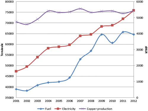
Figure shows the estimated energy demand and the copper production in the mining industry for the years 2001–2012 (Ocaranza et al. Citation2012; Zeballos and Betancour Citation2013). The copper production is measured in thousands of fine metric tons of mineral (kMTF) (purple line). The energy demand (fuel: blue line, electricity: red line) of the copper mining industry in Chile grew by 63% between 2001 and 2012 (Zeballos and Betancour Citation2013). In the same period, the production of copper increased by 15% (Ocaranza et al. Citation2012). Thus, the specific energy consumption per fine metric ton of copper increased (Betancour Citation2013), which may have the following reasons: The mines that have most recently started operation are surface mines, wherein the course of mineral removal, the distances of transport and the number of slope sections increase, which leads to an increased specific energy consumption (Betancour Citation2013). Also, in some places, the mineral extraction becomes more intensive in terms of energy because of increasing mining effort (e.g. ores of less quality), not only caused by higher transport complexity (Betancour Citation2013).
Figure 1. Estimated energy demand for copper mining.
2.1. Electricity demand projection until 2025
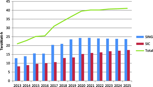
According to a report from Chilean Copper Corporation (Zeballos-Valenzuela and Betancour Citation2013), the increase in the copper production projected in the period 2013–2025 will indicate a proportional increase in the electricity demand. It estimates that by the year 2025, the copper mining industry will demand about 41.1 TWh of electricity a year, which means an increase by 96% compared to the demand in the year 2013, which reached about 21 TWh (Zeballos-Valenzuela and Betancour Citation2013). Figure shows the estimated evolution of the mining electricity demand until 2025, indicating that most of the growth is expected before 2020. In this period, the mining electricity demand will still be centred in the SING, though its prominent role in the year 2025 will decrease to 57.5% compared to 61% of the mining electricity demand in 2013 (Zeballos-Valenzuela and Betancour Citation2013).
Figure 2. Estimated evolution of the mining electricity demand until 2025 in the northern Chile interconnected power system (SING) and central Chile interconnected power system (SIC).
3. Copper mining processes
For this study, the copper manufacturing processes have been considered in order to evaluate the possibility of integration of solar technology for energy supply.
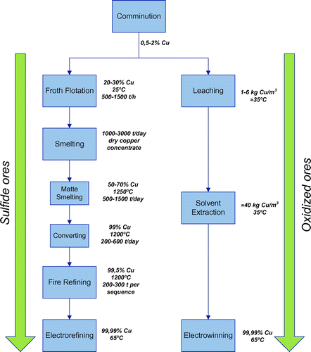
Copper is mainly present in the earth’s crust as copper–iron–sulphide and copper sulphide minerals as chalcopyrite (CuFeS2), chalcocite (Cu2S) and bornite (Cu5FeS4). The concentration of copper in an ore body is commonly about 0.5% for open-pit mines and between 1 and 2% for underground mines (Schlesinger et al. Citation2011). Copper can also be found in oxidized minerals like oxides, carbonates, hydroxy-silicates, sulphates, but in a lower concentration (Konečná and Fintová Citation2012; Schlesinger et al. Citation2011).
According to the ore composition, there are two types of copper extraction (Gibbons et al. Citation1988; Schlesinger et al. Citation2011):
| • | Copper extraction from sulphide ores (Pyrometallurgical) | ||||
| • | Copper extraction from oxidized minerals (Hydrometallurgical) | ||||
Thus, there are two branches of processes depending on the ore body composition. Each of the two branches starts with crushing and grinding (comminution) where boulders are processed to grains of sand (Gibbons et al. Citation1988). Crushing and grinding consume about 33–40% of the total energy required to produce refined copper (Gibbons et al. Citation1988). In the second step called beneficiation or concentration (Gibbons et al. Citation1988), sulphide minerals are taken to the flotation cells where the crushed and grinded mineral is wetted and converted into a water–ore mixture (pulp). Then, small streams of bubbles pass up through the pulp attaching to the Cu mineral particles. When bubbles get to the top of the pulp, they create a strong froth full of Cu particles (Schlesinger et al. Citation2011) that are taken to the smelting where molten copper sulphide (copper matte) is separated into blister copper (at least 98.5%) and slag (Gibbons et al. Citation1988). The final step is the conversion of the impure copper to pure copper as a result of the electrorefining (Schlesinger et al. Citation2011).
On the other hand, after comminution, the oxidized minerals pass through the process of leaching, which consists in dropping sulphuric acid uniformly through flat-surface heaps of crushed ore. The result is a pregnant solution that contains Cu which is prepared in the solvent extraction process for electrowinning where pure metallic copper is produced (Gibbons et al. Citation1988; Schlesinger et al. Citation2011). Figure shows a scheme of copper processes.
Figure 3. Copper processes scheme.
3.1. Selection of suitable applications
Each mining process has different needs in terms of temperature and energy, and some of them can be complemented with solar energy:
| • | Comminution and solvent extraction are processes that operate at ambient temperature. Therefore, there is no need to integrate any solar technology for process heat generation. | ||||
| • | Fire refining removes sulphur and oxygen from liquid blister copper by air-oxidation removal of sulphur as SO2, and hydrocarbon-reduction removal of oxygen as CO, CO2 and H2O (Schlesinger et al. Citation2011). These processes happen at 1200 °C and need hydrocarbon fuel, which makes the integration of solar technology not feasible. | ||||
| • | For froth flotation, a rise in the solution temperature from 25 to 50 °C entails an increase in the final product copper concentration, although it has been proved that this only works in some mineral compositions. So, its implementation should be studied depending on the mineral composition at each specific mine. | ||||
| • | Smelting needs temperatures around 1200 °C to smelt the mineral in furnaces specially adapted for the process. When melting of the mineral initiates (1200 °C), oxygen-enriched air is blown to begin its oxidization. This generates sufficient heat to make the process auto-thermal, decreasing the amount of fuel needed (Schlesinger et al. Citation2011). Concentrated solar technologies like central receivers can be studied to smelt directly the mineral or to provide hot air, although the constant energy demand (24 h a day), high flows and complex integration with the current technology make it hardly feasible. | ||||
| • | For oxidized minerals, leaching is not strongly dependent on heap temperature. On the other hand, sulphide ore bacteria needs favourable conditions of pH, ventilation and temperature (30–35 °C) to get the optimal efficiency. Some mines are located at high altitudes where temperature can decrease to 5 °C in some moments of the day. Therefore, heap can be heated blowing hot air, heated in solar air heaters, through pipes used for ventilation. | ||||
| • | Electrorefining and electrowinning are similar processes, they differ mainly in that electrowinning uses an inert Pb-alloy anode instead of soluble copper anodes and it needs a higher applied voltage. Both processes need to heat the electrolyte, before it enters the cell, to 65 °C, typically through diesel-powered heaters. The installation of low-medium-temperature solar thermal technologies to partially or fully heat the electrolyte should be an important case to study considering the range of temperatures, technology development and costs. | ||||
Table shows a summary of suitable solar technology for mining processes considering range of temperature, pros and cons. The processes are arranged from best to worst possibilities of implementing solar thermal technology.
Table 1. Analysis of suitable solar thermal technology for mining processes.
4. Case study
Due to the energy requirements of the mining industry and the huge solar energy available, it is a good opportunity to study the integration of solar energy for the mining process. For that purpose, a specific case has been analysed to demonstrate the usefulness of combining solar thermal energy with conventional energy for one of the processes needed by the copper industry.
This work will cover the “Ministro Hales” division of Codelco, which is located 5 km north from the city of Calama, in the region of Antofagasta, Chile. The production of copper is about 163,000 tons every year (MTF/year) (Gestión Citation2014). The mine works 340 days a year, 24 h a day. The days that the mine is not producing is due to maintenance issues.
4.1. Heat generation with solar technologies
As a result of the analysis made in Chapter 3.1, the integration of solar energy in the electrowinning process is being analysed. In Figure , a typical flowchart of the electrowinning process is shown.
Figure 4. Electrowinning conventional flowchart.
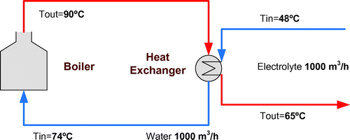
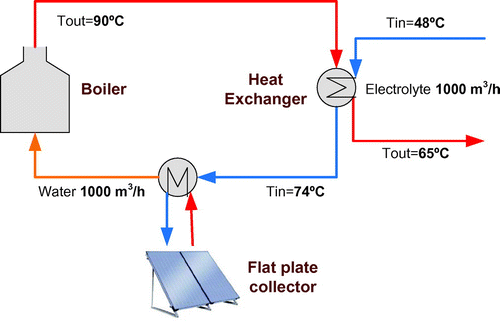
Figure shows flows and temperatures in the inlet and outlet of the electrolyte and the heating system. The heating system works 24 h a day with constant flow rates.
Thus, the boiler of the heating system works with a power capacity of 18.6 MWth, heating a water flow rate of 1000 m3/h from 74 to 90 °C. The electrolyte has a flow rate of 1000 m3/h that has to be heated from 48 to 65 °C.
Therefore, to supply the complete energy demand for the electrolyte, the solar thermal (ST) system should provide 18.6 MWth to the electrowinning process. To do as few modifications as possible of the previous flowchart, the ST system will be placed after the heat exchanger to preheat the water before it enters the boiler. Figure shows the modified flow chart.
Figure 5. Electrowinning conventional flowchart with flat plate collector integration.
4.1.1. Solar thermal technology selection
Because of the temperatures and flow rates of the process, as a first approach, the appropriate ST technologies are:
| • | Flat plate collectors (FPC) | ||||
| • | Parabolic Trough (PT) | ||||
Concentration technologies have the advantage of being able to reach higher temperatures (400 °C) than FPC (120 °C). Both technologies can operate in the range of temperature needed. Moreover, FPC needs smaller investment along with cheaper installation and maintenance costs compared with PT. Concentration technologies like PT can only operate with direct normal irradiance (DNI), unlike FPC that can capture global irradiance; this means that PT cannot operate in cloudy days as FPC does. Another disadvantage is that PT needs a tracking system which increases costs.
Comparing the efficiency and cost of each technology, FPC has a clear advantage vs. PT. Kalogirou (Kalogirou Citation2003) recommends, through an economic analysis, FPC for low-temperature process (under 120 °C) and sun concentration technologies for high-temperatures process (over 150 °C). According to these arguments, the appropriate technology to be used in this case should be FPC.
4.1.2. Electrowinning with FPC integration
The FPC to use is the ARCON HT-SA 28/10, which has a net area of 12.58 m2. This FPC has been used in big district heating projects in Denmark (ARCON-Solar Citation2013). The parameters of the efficiency curve of this collector are shown in Table :
Table 2. Efficiency parameters for collector model ARCON HT-SA 28/10.
The efficiency of the FPC is obtained with the Equation (1) (See nomenclature for the parameter definition):(1)
The following values have been assumed for the installation dimensions: medium operation temperature Tm of 82 °C; ambient temperature Ta of 25 °C, solar irradiance G of 950 W/m2. With those data, the FPC mean efficiency is η = 63.9%
To calculate the area of FPC to satisfy the energy demand, the following equation has been used: Q = η × A × G, with the following parameters value: Energy demand Q = 18.6 MWth, G = 950 W/m2, and η = 63.9%. So, the collector area to satisfy the energy requirements should be A = 30668 m2. This means that 2438 ARCON model FPCs are needed to meet the demand.
The volume of the accumulator tanks to use in the simulation has been: 1000, 2000 and 4000 m3.
Figure shows in detail the electrowinning process including the solar system and buffer tank.
Figure 6. Detail scheme of Electrowinning with insertion of FPC.
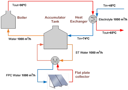
The simulation is made in TRNSYS (Citation2014) software for the period of one year. The radiation data is obtained from the METEONORM (Meteotest Citation2014) software for the city of Calama (Latitude: −22.31, Longitude: −68.91).
The operating principle of the FPC is such that the water pump constantly provides a flow rate of 1000 m3/h whenever incident solar power is sufficient to heat the water above the temperature of the accumulator tank.
4.1.3. Results
For the first simulation, areas of 11,000, 21,000 and 31,000 m2 have been chosen. These areas can supply 33.3, 66.6 and 100% of the energy demand for the design irradiance, respectively. The size of the accumulator tank has been considered constant for this case, with a capacity of 2000 m3.
The results are shown in Table . A Sankey diagram, which is an energy flow diagram where the width of the arrows is shown proportionally to the flow quantity, is shown in Figure (for 31000 m2 FPC area).
Table 3. Results for different FPC areas and constant 2000 m3 accumulator tank (energy MWh per year).
Figure 7. Sankey Diagram of 31,000 m2 FPC and 2000 m3 accumulator tank.
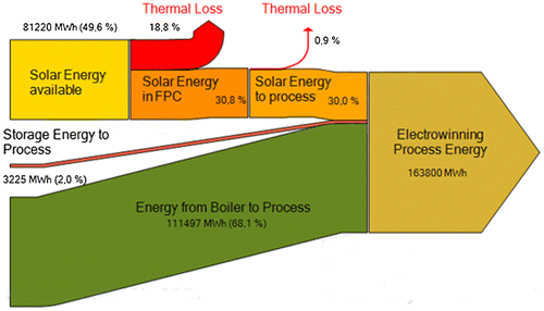
For all simulations, the process Energy is 163.800 MWh per year
For the second simulation, the sizes of the accumulator tank chosen were variable, considering three possible volumes, 1000, 2000 and 4000 m3, for a constant FPC area of 11,000 m2.
The results are shown in Table . A Sankey diagram for 4000 m3 accumulator tank is shown in Figure .
Table 4. Results for different accumulator tank sizes and constant 11,000 m2 FPC area energy (MWh per year).
Figure 8. Sankey Diagram of 11,000 m2 FPC area and 4000 m2 accumulator tank.
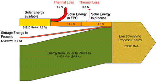
For all simulations, the solar energy available in FPC area is 28,820 MWh per year and available energy in FPC is 18,331 MWh per year, the FPC efficiency is 63.6%, and the process energy is 163,800 MWh per year.
In order to estimate the economic viability of the previous results, a calculation of net present value (NPV) and internal rate of return (IRR) for each case is shown. Because of the large size of the FPC area and the accumulator tank, their costs are taken from Ellehauge and Engberg-Pedersen (Citation2007) for district heating projects in Denmark, which have comparable or similar sizes. Generally, industrial facilities use much smaller FPC areas for their processes.
For the economic analysis, these parameters were used:
| • | Facility lifetime: 20 years | ||||
| • | Discount rate: 10% | ||||
| • | Annual maintenance: 1% of investment costs. | ||||
| • | Tax rate: 19% | ||||
| • | Inflation: 3.3% | ||||
For diesel, these parameters were used:
| • | Cost: 0.9 €/l | ||||
| • | LHV: 8640 kcal/l | ||||
| • | Boiler efficiency: 95% | ||||
With these parameters, the cost of the heating process with the use of a diesel boiler is: 0.09 €/kWh.
If electric heaters were used instead of diesel boilers, due to the higher electricity cost, the final cost of process heating would be higher as well.
Tables and show the results of the economic analysis carried out for the previous cases. The amount of money saved is directly associated to the annual amount of diesel not used due to the action of the thermal energy produced with the FPC and stored in the accumulator tank.
Table 5 Economic results for different FPC areas and 2000 m3 accumulator tank.
Table 6. Economic results for different accumulator tank sizes and 11,000 m2 FPC area.
From the results obtained, the cost of generating heat with the use of the FPC installation can be estimated through the levelized energy cost (LEC) indicator 0.017–0.019 €/kWh. This is 80% less cost than generating with diesel.
4.1.3.1. Greenhouse gases emission
Due to the action of FPC in the electrowinning process, diesel boilers reduce their operation during the day, thus reducing strongly the CO2 emissions. Table shows the avoided CO2 emissions for every FPC area chosen considering the first simulation data.
Table 7. Avoided CO2 emissions according to FPC area.
4.2. Electricity generation with solar thermal technology
The aim of this section is to simulate an STE plant to supply the electricity demand of the “Ministro Hales” mining deposit. The production of thin copper is 163,000 metric tons every year (MTF/year), with a demand of 11,028.2 MJ per MTF (Gestión Citation2014; Zeballos-Valenzuela and Betancour Citation2013). Additionally, the mine works 340 days a year, 24 h a day. With this information, it is possible to both calculate the electric power demand needed for the production of thin copper, and the estimated power of the power plant for its use during the scheduled working hours throughout the year. This gives an estimate of installed capacity of ~61 MW.
The purpose of this case study is to supply the entire electricity demand with the STE plant working at full load.
4.2.1. STE plant simulation
The STE plant analysed is a 61-MW PT power plant with 9 h molten salt storage. Table shows the characteristics of the plants.
Table 8. STE plant characteristic.
The SimulCET (García-Barberena et al. Citation2012; Zaversky et al. Citation2012) software is used to simulate the CSP plant. In this study, the PT solar plant will be simulated for one year operation. Hourly sun radiation data are obtained for one year from METEONORM (Meteotest Citation2014) software.
A techno-economical optimization of the solar power plant was carried out with SimulCET in order to obtain the most convenient size of the solar field. For that purpose, several annual simulations with different number of loops (solar multiple) were executed with SimulCET.
For the simulations, the following parameters were used:
| • | Debt of total investment: 70% | ||||
| • | Years to pay off debt: 15 | ||||
| • | Power plant lifetime: 25 years | ||||
| • | Discount rate: 5.36% | ||||
Distribution and transmission costs are not considered.
4.2.2. Results
Table shows the simulation results for LEC according to the PT area.
Table 9. LEC according to solar multiple.
The lowest LEC resulted for a solar multiple of 2.45 and 200 loops. However, the 180 loops case was finally considered due to the small difference in LEC and the lower risk for the investor (Figure ).
Figure 9. LEC according to PT number of loops.
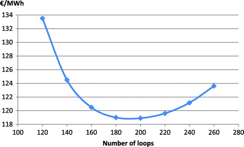
Table shows the final solar power plant characteristics:
Table 10. Solar power plant parameters.
The same simulation was performed for an identical power plant located near Granada in the south of Spain, where the solar resource is 2136 kWh/m2/year (NREL Citation2013), 25.6% less than the DNI found in Calama, Chile. This simulation has been performed in order to compare the LEC of the same plant in Spain and Chile in order to see the benefits in radiation and LEC. The LEC in Spain was found to be 155.5 €/MWh, which is by 30% higher than the LEC calculated for Calama.
4.2.2.1. Greenhouse gases emissions
Pure solar power plants without the use of gas fuelled backup system do not emit greenhouse gases to the environment. Therefore, the use of these types of technologies would avoid releasing CO2 to the environment that would have been released if the same electricity had been provided by the northern Chile interconnected power system (SING). Table shows some estimates of the avoided CO2 emissions with the use of PT instead of feeding the system with SIC or SING. The avoided emissions would be about 156,107 tons of CO2 per year.
Table 11. Emission factors and avoided emissions for SIC and SING.
5. Conclusions and discussion
5.1. Solar thermal conclusions
Almost all mining processes require huge amounts of energy in terms of heat which is mostly provided by conventional energy resources with their big impact on the environment. The excellent solar resource found in the regions of northern Chile provides good perspectives for its implementation in the mining processes with lower costs and emissions than fossil energy sources.
The processes with best chances for solar energy implementation are electrowinning and electrorefining, due to its medium-low temperature requirement. Also, leaching has good future prospects with more technical difficulties though. The obstacles for the other processes like fire refining and smelting are the elevated temperatures (~1200 °C) and flows involved, that may be provided in the future with improved solar energy technology.
The process chosen for its analysis was electrowinning, with a long-term cost of 0.018 €/kWh, for heating the electrolyte through flat plate collectors; this is 80% less cost with respect to the use of conventional diesel boilers (estimated to be 0.09 €/kWh). Considering the configuration analysed in this study, it is noteworthy that flat plate collectors cannot be used without the diesel boiler because electrowinning in mines requires 24 h a day operation. Nevertheless, it should be mentioned that larger FPC areas together with larger thermal energy storage should theoretically allow a pure solar powered operation without the requirement for conventional diesel boilers.
From the results, it can be concluded that with the economic parameters employed, all the cases studied are economically viable. From Table , it is seen that when increasing the size of the collector field, the NPV and IRR increase and the payback period decreases. Therefore, the size of the collector field can be still increased; however, we considered 31,000 m2 a reasonable area compared with the biggest installation found in Marstal, Denmark (Ellehauge and Engberg-Pedersen Citation2007) with 18,365 m2. The decision of increasing the collector area would be associated to the size of the investment that could be achieved and the technical supplies required.
Regarding the size of the accumulator tank, a volume of 2000 m3 would be the most efficient alternative. For all the tank volumes reviewed in this study, there is no big difference in the amount of energy supplied to the process; hence, the size of the tank should be selected with another criterion than the process flows and it should be sized as a buffer tank.
Moreover, implementing solar technologies will lead to a significant CO2 emission reduction. Depending on the total flat plate collector area, up to 14,204 tons of CO2 may be saved for the studied cases.
5.2. Solar thermal electricity conclusions
Chile has great advantages for the introduction of solar thermal power generation. The big amount of direct normal irradiation throughout the year, 30% more than in most places in Europe, allows high rates of electricity generation reducing the LEC below currently operating projects. Furthermore, high irradiation areas coincide with high energy demand locations as the major mining centres.
The LEC obtained for the 61-MW power plant was 119 €/MWh, not far from the 96.9 €/MWh SING average cost, however below the 155.5 €/MWh as estimated for the same power plant in the province of Granada, Spain.
One of the great advantages of the solar technology is that it does not emit greenhouse gases to the environment. Its operation would avoid releasing 156,107 tons of CO2 per year, which can be traded on the global market as CERs (Certified Emission Reduction). It is estimated that each ton of CO2 can be traded between 7 and 20 € depending on the characteristics of the project, which on average can provide additional incomes close to a million Euros per year for this project.
In the medium term, the most likely scenario is:
| • | Significant increase in energy demand due to new mining projects. | ||||
| • | Reduction in the costs of PT technology investment. | ||||
| • | Rise in the fuel cost, thus increasing the electricity cost in SING. | ||||
| • | Trade of CERs. | ||||
It is estimated that in the medium term, the PT technology will be truly competitive in the SING, reducing the greenhouse gas emission and giving more independence to the power supply from fossil sources.
| Abbreviation | ||
| CER | = | Certified Emission Reduction |
| CR | = | Central Receiver |
| DNI | = | Direct normal irradiance |
| FPC | = | Flat Plate Collectors |
| IRR | = | Internal Rate of Return |
| LEC | = | Levelized Cost of Electricity |
| MTF | = | Metric Tons of Fine Grade |
| NPV | = | Net Present Value |
| O&M | = | Operation and Maintenance |
| RES | = | Renewable Energy Sources |
| SING | = | Sistema Interconectado del Norte Grande |
| SIC | = | Sistema Interconectado Central |
| STE | = | Solar Thermal Electricity |
| PT | = | Parabolic Trough |
| Symbols | ||
| η0 | = | Optical efficiency (–) |
| a1 | = | Linear heat loss coefficient (W/Km2) |
| a2 | = | Quadratic heat loss coefficient (W/K2 m2) |
| Ta | = | Ambient temperature (°C) |
| Tm | = | Medium operation temperature (°C) |
| G | = | Solar irradiance (W/m2) |
| CuFeS2 | = | Chalcopyrite |
| Cu2S | = | Chalcocite |
| Cu5FeS4 | = | Bornite |
Disclosure statement
No potential conflict of interest was reported by the authors.
Acknowledgements
We would like to thank them both University of Chile and CENER heartily. The authors would also like to thank Dr. Pierre Garcia, Enric Mateu, as well as Ana Monreal for their dedicated work.
Funding
This work was co-funded by the University of Chile with a grant for a 4 months stay for Eduardo Chandia at the facilities of CENER in Sarriguren (Navarre, Spain) in 2011.
References
- Antofagasta-Minerals. 2014. Planta Termosolar Minera El Tesoro. Antofagasta Minerals S. A. http://www.aminerals.cl.
- Araneda, J. C., S. Mocarquer, R. Moreno, and H. Rudnick. 2010. “Challenges on Integrating Renewables into the Chilean Grid.” Paper Presented at the Power System Technology (POWERCON), 2010 International Conference on, October 24–28, 2010.
- ARCON-Solar. 2010. ARCON Solar Collector – Type HT-SA 28/10 – Datasheet. Skørping: ARCON Solar A/S.
- ARCON-Solar. 2013. Large-Scale Solar Heating Plants. Skørping: ARCON Solar A/S.
- Betancour, María Cristina. 2013. Investment, exploration and strategic supplies for the mining industry. [Inversión, exploración e insumos estratégicos para la minería.] Santiago de Chile: Comisión Chilena del Cobre – Ministerio de Minería.
- Ellehauge, Klaus, and Thomas Engberg-Pedersen. 2007. Solar Heat Storages in District Heating Networks. Denmark: Ellehauge & Kildemoes,Vestergade, COWI A/S, Lyngby.
- Gajardo Aníbal C., T. Rodolfo Olivares, M. Soraya Nazarala, O. Rodrigo Carrasco, M. Carlos Arias, G. Jorge Campos, U. Jennifer Greig, C. Javier Jara, Marco Padilla, and Zúñiga I. Ema. 2012. Yearbook of Chilean mining industry. [Anuario de la Minería de Chile.] Santiago: Servicio Nacional de Geología de Chile – Ministerio de Minería.
- García-Barberena, Javier, Pierre Garcia, Marcelino Sanchez, Manuel J. Blanco, Carlos Lasheras, Asun Padrós, and Jaime Arraiza. 2012. “Analysis of the Influence of Operational Strategies in Plant Performance Using SimulCET, Simulation Software for Parabolic Trough Power Plants.” Solar Energy 86 (1): 53–63. doi:10.1016/j.solener.2011.09.018.
- Garrido, F., R. Soto, J. Vergara, M. Walczak, P. Kanehl, R. Nel, and J. García. 2012. “Solar Pond Technology for Large-Scale Heat Processing in a Chilean Mine.” Journal of Renewable and Sustainable Energy 4 (5): 053115 ; doi:http://dx.doi.org/10.1063/1.4757627.
- Garrido, F., and J. Vergara. 2013. “Design of Solar Pond for Water Preheating Used in the Copper Cathodes Washing at a Mining Operation at Sierra Gorda, Chile.” Journal of Renewable and Sustainable Energy 5 (4): 043103 ; doi:http://dx.doi.org/10.1063/1.4812652.
- Gestión. 2014. Minera Codelco prevé producción récord de cobre de 1.9 millones toneladas para el 2014. Gestión – El Diario de Economía y Negocios de Perú. http://www.gestion.pe.
- Geyer, Michael, E. Lüpfert, Rafael Osuna, Antonio Esteban, Wolfgang Schiel, Axel Schweitzer, Eduardo Zarza, Paul Nava, Josef Langenkamp, and Eli Mandelberg. 2002. EUROTROUGH – Parabolic Trough Collector Developed for Cost Efficient Solar Power Generation. Zurich: SolarPACES.
- Gibbons, John H., George S. Ansell, Lionel S. Johns, Peter D. Blair, and Jenifer Robison. 1988. Copper: Technology and Competitiveness. Washington, DC: US-Congress – Office of Technology Assessment.
- IEA. 2012. Oil & Gas Security – Emergency Response of IEA Countries. Paris: IEA – International Energy Agency.
- Kalogirou, S. 2003. “The Potential of Solar Industrial Process Heat Applications.” Applied Energy 76 (4): 337–361.10.1016/S0306-2619(02)00176-9
- Kearney, D. W. 2007. Parabolic Trough Collector Overview – Notes on a Bit of History, Development after Luz, and a Recent Surge in Trough Collector Technology Offerings. Golden: NREL – National Renewable Energy Laboratory.
- Konečná, Radomila, and Stanislava Fintová. 2012. Copper and Copper Alloys: Casting, Classification and Characteristic Microstructures, Copper Alloys – Early Applications and Current Performance – Enhancing Processes. Intech – Open science – Open minds. http://www.intechopen.com.
- Larraín, Teresita, and Rodrigo Escobar. 2012. “Net Energy Analysis for Concentrated Solar Power Plants in Northern Chile.” Renewable Energy 41: 123–133. doi:10.1016/j.renene.2011.10.015.
- Larraín, Teresita, Rodrigo Escobar, and Julio Vergara. 2010. “Performance Model to Assist Solar Thermal Power Plant Siting in Northern Chile Based on Backup Fuel Consumption.” Renewable Energy 35 (8): 1632–1643. doi:10.1016/j.renene.2010.01.008.
- Meteotest. 2014. Meteonorm – Global Meteorological Database. Genossenschaft Meteotest. www.meteonorm.com.
- Ministerio-de-Economía. 2007. Ley general de servicios eléctricos, Decreto con fuerza de ley n. 4, Art. único N. 2, D.O. 01.04.2008. Ministerio de Economia, Fomento y Turismo, Santiago de Chile.
- NREL. 2013. Concentrating Solar Power Projects – Andasol 1. NREL – National Renewable Energy Laboratory. http://www.nrel.gov.
- NREL. 2014. Concentrating Solar Power Projects – Planta Solar Cerro Dominador. NREL – National Renewable Energy Laboratory. www.nrel.gov.
- Ocaranza, A. Juan, María Cristina Betancour, U. Arce Oscar, V. Pérez Vicente, V. Zeballos Jorge, G. Cifuentes Cristian, S. Venegas Luis, and V. Maldonado Paula. 2012. Yearbook of copper and other mineral statistics 1993 - 2012. [Anuario de Estadísticas del Cobre y otros Minerales 1993-2012.] Santiago: COCHILO – Comisión Chilena del Cobre.
- Ortega, Alberto, Rodrigo Escobar, Sergio Colle, Samuel Luna de Abreu. 2010. “The State of Solar Energy Resource Assessment in Chile.” Renewable Energy 35 (11): 2514–2524. doi:10.1016/j.renene.2010.03.022.
- Rudnick, H., J. C. Araneda, and S. Mocarquer. 2009. “Transmission Planning-from a Market Approach to a Centralized One-the Chilean Experience.” Paper Presented at the Power & Energy Society General Meeting, 2009, PES ‘09. IEEE, July 26–30, 2009.
- Schlesinger, Mark E., Matthew J. King, Kathryn C. Sole, and William G. Davenport. 2011. Extractive Metallurgy of Copper. 5th ed. Oxford: Elsevier.
- Servert, J., A. Labanda, E. Fuentealba, M. Cortes, and R. Pérez. 2014. “Quality Function Deployment Analysis for the Selection of Four Utility-Scale Solar Energy Projects in Northern Chile.” Energy Procedia 49: 1896–1905. doi:10.1016/j.egypro.2014.03.201.
- TRNSYS. 2014. TRNSYS – A Transient System Simulation Program. University of Wisconsin Madison. http://sel.me.wisc.edu/trnsys/.
- Zaversky, Fritz, Javier García-Barberena, Marcelino Sánchez, and David Astrain. 2012. “Probabilistic Modeling of a Parabolic Trough Collector Power Plant – An Uncertainty and Sensitivity Analysis.” Solar Energy 86 (7): 2128–2139.10.1016/j.solener.2012.04.015
- Zeballos, V. Jorge, and María Cristina Betancour. 2013. Actualización de información sobre el consumo de energía asociado a la minería del cobre al año 2012. Comisión Chilena del Cobre – Ministerio de Minería – Gobierno de Chile. http://www.cochilco.cl/.
- Zeballos-Valenzuela, Jorge, and María Cristina Betancour. 2013. Proyección del consumo de energía eléctrica de la minería del cobre en Chile al 2025. Comisión Chilena del Cobre. http://www.cochilco.cl.