Abstract
To increase the efficiency of photovoltaic (PV) systems, maximum power point (MPP) tracking of the solar arrays is needed. Under partially shaded conditions (PSCs), the solar arrays power–current (P–I) characteristic has multiple MPP. This paper presents various methods and approaches of tracking the MPP from a PV generator operating under PSC. Some comparisons, advantages, drawbacks and critical analysis of each method are discussed. It was found that, indirect methods use empirical data or mathematical expressions of numerical approximations to estimate the MPP from the PV generator’s voltage, current and irradiance. Direct methods offer the advantage of obtaining the actual maximum power from the PV generator’s voltage and current. Artificial intelligence methods do not need exact mathematical models. They can perform under parameter variation, load and supply voltage disturbances. Finally, novel methods require less number of iterations to converge, independent to the initial conditions. All these algorithms can be included in some of the DC/DC converters and MPP trackers for stand-alone or grid-connected systems.
1. Introduction
Photovoltaic (PV) energy has become an attractive option among renewable energy sources because of its sustainability, cleanliness and maintenance-free (Liu et al. Citation2013). Besides this, it is scalable from very small to very large and easy to integrate with existing power converters. Although the rapid development of PV materials technology and the increasing demand for PV modules, the capital costs of PV systems are still very high (Poponi Citation2003). There is therefore a necessity to design a power converter that is not only high in efficiency but also optimizes the energy production of the PV material. Various power suppliers using renewable energy sources have attracted a great deal of attention with the trend of electric power deregulation and environmental preservation in the past years. Among these power supply systems, PV is particularly desirable due to its constant efficiency over a wide range of capacity as well as the flexibility of location for installation. However, the output density of the PV system is low and depends highly on the insolation condition and surface temperature of the PV array. Moreover, there may be multiple local maximum power points (MPPs) in the current–power (I–P) curve under non-uniform insolation, whereas only one MPP under uniform insolation. In fact, PV plants are affected by shadows projected between PV arrays mainly at sunrise and sunset. Literature on the impact of shade on PV array output power is plentiful, with studies based on the consideration of the whole current–voltage (I–V) curve (Moreno, Muňoz, and Lorenzo Citation2010).
Considering the above-mentioned situation, maximum power point tracking (MPPT) control must be performed to maximize the efficiency of the PV system (Kobayashi, Ichiro, and Yoshio Citation2006). MPPT algorithms with quick response and that can extract maximum power from the PV arrays in real time are therefore essential (Liu et al. Citation2013). In those systems, the performance relies on the operating conditions and the maximum power extracted from the PV generator depends strongly on three factors: insolation, load impedance and cell’s temperature. The output power of a PV module also varies with its operating point because of the inherent non-linear current–voltage relationship of a typical PV cell. A MPPT algorithm is commonly used to maximize the power drawn from PV modules under varying atmospheric conditions (Ahmed and Miyatake Citation2008). Nevertheless, PV systems should be designed to operate at their maximum output power levels for any temperature and solar irradiation level at all times (Salas et al. Citation2006).
Tracking the MPP is not easy when a PV array is partially shaded or installed in a rapidly variable insolation conditions. Although the static tracking efficiency of conventional MPPT method is usually high, it drops noticeably in case of rapidly changing irradiance conditions (Liu et al. Citation2013). In the last decades, many MPPT techniques suitable for fast changing environments or partially shaded condition (PSC) have been proposed in both analogue and digital forms. Chun et al. (Citation2010) categorized MPPT methods applicable under non-uniform insolation conditions into two groups, namely software-based algorithms (Nguyen and Low Citation2010; Salam et al. Citation2012; Syafaruddin, Karatepe, and Hiyama Citation2009, Citation2012) and hardware-based algorithms (Shimizu et al. Citation2001). Software-based methods track the global peak among the multiple peaks during PSCs while hardware-based algorithms try to avoid the multi-peaking effects of the bypass diodes in non-uniform insolation conditions (Shimizu et al. Citation2001). Ji et al. (Citation2009) proposed an approach based on the movement of the operating point through a linear function around the entire power–voltage (P–V) curve. They used the conventional MPPT to track the global peak. Shimizu et al. (Citation2001) showed that the P–V curve has only one MPP by a judicious choice of an optimum combination of off-duty ratios when PSCs occur.
This paper aims to present a review of various methods and approaches of tracking the MPP of a PV generator operating under partially shaded or rapidly variable insolation conditions.
2. The partially shaded module problem and MPPT
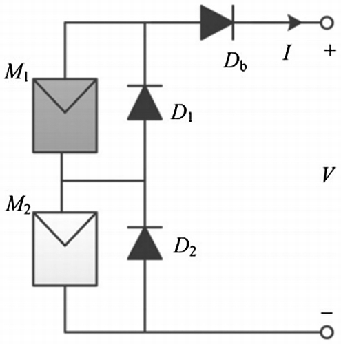
PV cells are highly sensitive to partial shading. If a cell or a portion of a module in a series string is shaded, then instead of contributing to the power output, the shaded cell(s) absorb(s) the power from the other cells in the string. The absorbed energy is converted into heat, contributing to hotspots that can damage the cell(s) (Jian, Maskell, and Patra Citation2013; Salas et al. Citation2006). However, most commercial modules use bypass diodes across a series of cells to overcome this effect. As shown in Figure , the bypass diodes (D1 and D2) are added to the PV system by connecting them parallel with the PV modules. In addition, the blocking diode (Db) is usually connected in the PV string in a series to prevent the reverse current from the load or unbalanced current flow from other paralleled PV strings (Jian, Maskell, and Patra Citation2013). The presence of shading in PV generators also causes disproportional power losses that are difficult to quantify (Rodrigo et al. Citation2013). In general, to calculate these losses, two approaches can be used. The first consists to use a model based on solving the whole I–V curve of the generator. These kinds of models are accurate, but difficult to implement, require a great deal of information as input and extensive computation. The second option consists to use a simplified model, easy to implement and fast. This option is preferable in practical applications and can be easily integrated in common yield estimation software (Rodrigo et al. Citation2013).
Figure 1. A small PV system with two PV modules, module M1 is shaded and M2 is receiving normal irradiance (1000 W/m2) (Jian et al. Citation2013).
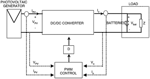
As mentioned earlier, tracking the MPP is not easy when a PV array is partially shaded or installed in a rapidly variable insolation conditions. The generator’s P–V characteristic may show multi-local maximum operating points. In this case, the operating point of the PV system can tend to converge to a local maximum operating point which is not the real maximum one on the P–V curve (Sun et al. Citation2002). In the literature, many authors proposed some control systems to avoid this difficulty, but most of them are still complicated (Sun et al. Citation2002) and sometimes not easy to be implemented. However, in order to overcome the undesired effects on the output PV power and draw its maximum power, it is possible to insert a DC/DC converter between the PV generator and the batteries, which can control the seeking of the MPP, besides including the typical functions assigned to the controllers. These converters are normally named as MPPTs. They consist of a topology and control circuit where there will be a MPP seeking algorithm (Salas et al. Citation2006). As shown in Figure , the input DC–DC converter part of a typical MPPT system is formed by the PV array and the output section by the batteries and load. The role of the MPPT is to ensure the operation of the PV generator at its MPP, extracting the maximum available power. The main objective being to obtain the maximum power from the PV generator for the first-load batteries stage i.e. when the batteries are fully or partially discharged, in some state of charge less than 100%, then it is necessary to control one/or some of the input/output (Salas et al. Citation2006).
Figure 2. General block diagram of a stand-alone PV system with MPPT (Salas et al. Citation2006).
3. Characteristics of a PV array under non-uniform insolation conditions
In any outdoor environment, the whole or some parts of the PV system might be shaded by trees, passing clouds, high building, etc, which result in non-uniform insolation conditions.
During partial shading, a fraction of the PV cells which receive uniform irradiance still operate at the optimum efficiency. Since current flow through every cell in a series configuration is naturally constant, the shaded cells need to operate with a reverse bias voltage to provide the same current as the illuminated cells (Mäki and Valkealahti Citation2012). However, the resulting reverse power polarity leads to power consumption and a reduction in the maximum output power of the partially shaded PV module. Exposing the shaded cells to an excessive reverse bias voltage could also cause hotspot to appear in them, and creating an open circuit in the entire PV module. This is often solved with the inclusion of a bypass diode to a specific number of cells in the series circuit (Silvestre, Boronat, and Chouder Citation2009).
PV arrays are generally characterized by I–V and I–P functions. The characteristics of a PV array show various modes under non-uniform insolation conditions that can be characterized by the following equations (Kobayashi, Ichiro, and Yoshio Citation2006):(1)
(2)
where α is the incremental value of Isc when surface temperature changes by 1 °C (A/°C) (under the standard condition); β is the incremental value of Voc when surface temperature changes by 1 °C (V/°C) (under the standard condition); Rs is series resistance of a module (Ω) (under the standard condition), Isc is the short circuit current (under the standard condition), V2, I2, E2 and T2 are voltage, current, insolation intensity and surface temperature of a module under the standard condition, and V1, I1, E1 and T1 are measured values of voltage, current, insolation intensity and surface temperature of the module.
4. MPPT methods for PV modules under PSCs
Various methods of tracking the MPP of a PV module under PSC are reported in the literature. According to the basic approaches used, they can be classified into four main groups: indirect methods, direct methods, artificial intelligence methods and novel methods. When the operating conditions of the PV array are smooth and stable, then the conventional MPPT methods can provide high-performance tracking. But, in places where the irradiation changes rapidly due to variable atmospheric conditions such as clouds, the overall tracking efficiency of the conventional techniques may drop noticeably (Liu et al. Citation2013) and cause power loss (Doostabab et al. Citation2013). Nevertheless, these techniques may be modified to be adapted to PSC. This section will focus on methods that are commonly used to track the MPP of a PV generator under partially shaded or installed in a rapidly variable insolation conditions.
4.1. Indirect MPPT methods under PSCs
Indirect MPPT control algorithms are based on parameters and data such as the typical curves of the PV generator for different irradiances and temperatures, or mathematical functions obtained from empirical data to estimate the MPP.
4.1.1. Voltage/current-based methods
Voltage-based method consists of a linear relationship between the solar array voltage corresponding to the maximum power () and solar array open-circuit voltage (Voc) (Salas et al. Citation2006):
(3)
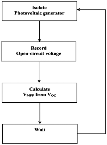
is the voltage factor depending mainly on the PV cells technology, fill factor and meteorological conditions. The literature reports KV values ranging from 0.73 to 0.80 for polycrystalline modules (Schoeman and Van Citation1982), and a typical interval of sampling of 15 ms (Schoeman and Van Citation1982). Algorithms of voltage-based MPPT method are widely presented in Salas et al. (Citation2006), Schoeman and Van (Citation1982) and Masoum and Dehbonei (Citation1998). They consist to measure the generator’s open-circuit voltage by interrupting the normal operation of the system for a given frequency, and to locate the MPP according to Equation (Equation3
(3) ). The operation voltage is adjusted to the maximum voltage point. The flow chart of the method is presented in Figure .
Figure 3. Flow chart of the voltage-based maximum power point tracking technique (Salas et al. Citation2006).
Current-based technique uses the same principle as the voltage-based method. Here, the solar array current (Imp) corresponding to the maximum power is assumed to be proportional to the solar array short-circuit current (Isc) (Salas et al. Citation2006):(4)
KI is the “current factor” depending also on the cells technology, fill factor and meteorological conditions. For polycrystalline modules, KI is around 0.85 (Noguchi, Togashi, and Nakamoto Citation2002; Salas et al. Citation2006). But in many cases, the way of determining KI is more complicated (Noguchi, Togashi, and Nakamoto Citation2002). The flow chart of the method is similar to that of the open-circuit voltage method (Salas et al. Citation2006).
4.1.2. Curve-fitting method
The method is based on the P–V characteristic of a PV generator given by (Masoum and Dehbonei Citation1998; Salas et al. Citation2006):(5)
where a, b, c and d are coefficients determined by the sampling of m values of PV voltage (VPV), PV current (IPV) and PV power (PPV) in a required interval. The voltage at which the power becomes maximum is obtained through the relation (Masoum and Dehbonei Citation1998):(6)
In practice, the process should be repeated every few milliseconds (ms) in order to find a fine MPP. The accuracy depends on the number of samples (Salas et al. Citation2006).
4.1.3. Look-up table method
In the look-up table method, the measured values of the PV generator’s voltage and current are compared to those stored in the control system memory, corresponding to the operation in the maximum point under concrete climatological conditions. The method is widely explained in Ibrahim et al. (Citation1999).
4.1.4. Open-circuit voltage test cell method
The method is deeply presented in Louis (Citation1972). It consists to measure the PV generator’s open-circuit voltage from a single cell, which is electrically independent to the rest of the PV array. The resulting values of the constant K are therefore applied to the main PV generator as in the case of voltage/current-based methods (Salas et al. Citation2006):(7)
4.2. Direct MPPT methods under PSCs
Direct MPPT control methods use the variations of the PV generator operating points to determine the optimum point from the PV voltage and/or current measurements (Salas et al. Citation2006). According to their implementation procedure, they could be classified into sampling and modulation methods. In sampling methods, a sample of the PV generator’s voltage and current is chosen. Using various strategies in each sample, the PV output power is gathered. The optimum power is thereafter determined. The methods of this category include among others: perturb and observe (P&O) method, particle swarm optimization (PSO) method, incremental conductance (InCond) method, parasitic capacitance method, differentiation method, two-stage MPPT control method and only current PV method. In these methods, the appropriate adjustment for the maximum voltage point leads to a point closed to or oscillating around the maximum point. These oscillations are generated automatically by the feedback control used. Modulation techniques like forced oscillation method is used to minimize the perturbations.
4.2.1. P&O method
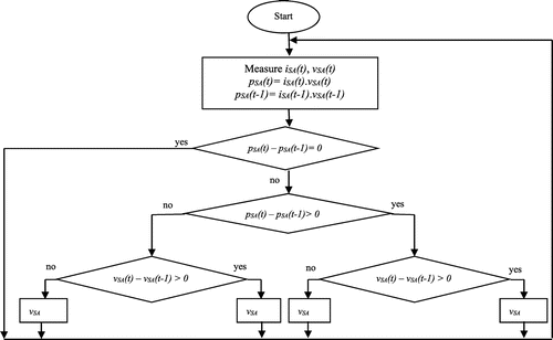
Among MPPT techniques, the P&O method is the most popular commonly used in practice by authors (Al-Atrash, Batarseh, and Rustom Citation2005; Kim, Jo, and Kim Citation1996; Salas et al. Citation2006; Teulings, Marpinard, and Capel Citation1993). The name of the algorithm itself reveals that it operates by periodically perturbing the control variable and comparing the instantaneous PV output power after perturbation with that before. Therefore, continuous perturbation or oscillation occurs around the MPP in steady state (Salas et al. Citation2006). In a typical P&O MPPT algorithm, the operating voltage of the solar array is perturbed in a given direction, and the power variation is observed. If power variation is positive, this means that the operating point has moved closer to the MPP, and, therefore, the operating voltage must be further perturbed in the same direction; otherwise, if power variation is negative, the operating point has moved away from the MPP, and, therefore, the direction of the operating voltage perturbation must be reversed. The conventional P&O method has been shown to track in the wrong direction under sudden increase/decrease in irradiance if the effect of irradiance change is greater than that of the perturbation step applied (Liu et al. Citation2013). Some improvements could be made to adapted to PSC (Ahmed and Miyatake Citation2008; Mohammad, Saeedeh, and Abdi Citation2013). The flow chart of the P&O algorithm is presented in Figure .
Figure 4. Flow chart of the P&O algorithm (Mohammad, Saeedeh, and Abdi Citation2013).
4.2.2. PSO-based method
PSO is a population-based evolutionary technique. Kennedy and Eberhart (Citation1995) were the first to propose the method in 1995. PSO is one of the strong optimization techniques based on group movement and intelligence. It was inspired by the social behaviour of bird flocking and fish schooling (Hinchey, Sterritt, and Rouff Citation2007; Mohammad, Saeedeh, and Abdi Citation2013). Its key advantages are the ability to escape from local maxima, easy to implement and fast convergence. PSO can find the global peak and is applied to determine the solar array MPP under partially shading condition. However, the standard version of PSO is not able to operate under PSC. Liu et al. (Citation2012) and Mohammad, Saeedeh, and Abdi (Citation2013) proposed a PSO-based method of tracking the MPP by modifying the standard version of PSO to meet the practical consideration of PV generator system under PSC. The block diagram of the PSO-based MPPT algorithm for PSC is presented in Figure (Liu et al. Citation2012).
Figure 5. Block diagram of the PSO-based MPPT algorithm for PSC (Liu et al. Citation2012).
4.2.3. InCond method
Another alternative to the P&O method was proposed by Hussein et al. (Citation1995), through the InCond method, based on differentiating the PV power with respect to voltage and setting the result to zero:(8)
InCond method tracks the MPP accurately by comparing the InCond dI/dV and chord conductance I/V (Salameh and Taylor Citation1990). This algorithm presents the advantage that no oscillation occurs around the MPP in steady state. However, the drawback of the method is the complexity to design its controller (Ahmed and Miyatake Citation2008).
4.2.4. Parasitic capacitance method
This method developed by Branbrilla et al. (Citation1999) is similar to the InCond method, except that the effect of the PV cell’s parasitic union capacitance is included.
4.2.5. Differentiation method
Differentiation method is widely presented in Bavaro and Bates (Citation1988) and David (Citation1968). It is based on solving the following equation to locate the MPP:(9)
However, solving this equation requires at least eight calculations and measurements. Furthermore, if the final sum is not zero, a ninth calculation must be made to determine the direction that the operating point must be adjusted to reach the MPP.
4.2.6. Two-stage MPPT control method
Two-stage MPPT control process consists to two steps. The first stage moves the operating point to the vicinity of the real peak power point to avoid converging to the local MPP. The control reference of the first step is an equivalent load line Rpm which is defined by Equation (Equation10(10) ) as the ratio of the optimal operating voltage Vpm to the optimal operating current Ipm under uniform insulation. In other words, the operating point at the end of the first control is the point (2) in Figure which is the intersection between the I–V curve and the load line (Kobayashi, Ichiro, and Yoshio Citation2006).
(10)
Figure 6. Operation of two-stage MPPT control on I–V and I–P curve (Kobayashi, Ichiro, and Yoshio Citation2006).
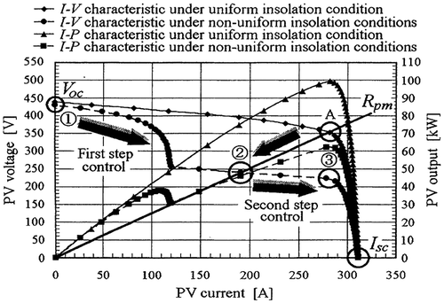
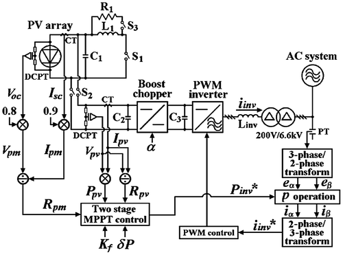
After reaching the point (2), the control mode will be switched to the second stage mode and the dV/dI control algorithm is used i.e. the inverter will be controlled so as to minimize the difference between V/I and dV/dI. Then, the operating point will converge to the point (3) in Figure . The method enables relatively simple control process even under rapidly changing non-uniform insolation. The two-stage MPPT control method combined to the instant online measurement of Voc and Isc shows a response time of the control system within 0.3 s even under the great change of insolation pattern. Figure shows the whole control process of this MPPT method.
Figure 7. A two-stage MPPT control process (Kobayashi, Ichiro, and Yoshio Citation2006).
4.2.7. Only current PV method
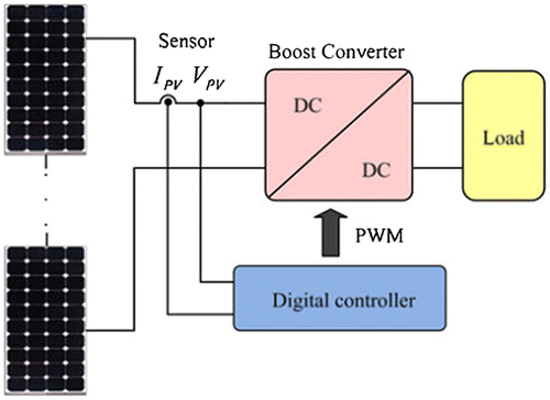
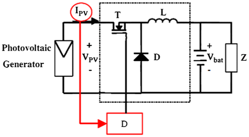
Up to now, in the direct methods, the PV voltage and current have been measured. However, it is possible to find a method that only uses the PV current (Branbrilla et al. Citation1999; Hussein et al. Citation1995); e.g. Only current PV method. Block diagram of a stand-alone PV system with the only current PV algorithm is presented in Figure . The method is widely presented in Salas et al. (Citation2006).
Figure 8. Block diagram of a stand-alone PV system with the only current PV algorithm (Salas et al. Citation2006).
4.2.8. Forced oscillations method
Several papers have dealt with this method (Cocconi and Rippel Citation1990; Tse et al. Citation2001). The principle used in Cocconi and Rippel (Citation1990) consisted in introducing a small voltage of 100 Hz, which is added to the operation voltage of the PV generator. This leads to a ripple power, whose phase and amplitude are dependent on the relative location of the operation point to the MPP.
4.3. Artificial intelligence MPPT methods under PSCs
In recent years, artificial intelligence methods have received attention and increased their use successfully in the implementation of MPP searching. Among the most used in MPPT control, we have enhanced fuzzy logic P&O MPPT, Fibonacci line search (FLS) and artificial neural network (ANN) methods.
4.3.1 Enhanced fuzzy logic P&O MPPT method
Based on their heuristic nature and fuzzy rule tables, these methods use different parameters to predict the maximum power output:
| • | output circuit voltage and short circuit current (Wilamowski Citation2001); | ||||
| • | instantaneous array voltage and current (El-Shafy, Faten, and Abou El-Zahab Citation2003; Patcharaprakiti, Premrudeepreechacharn, and Sriuthaisiriwong Citation2005; Won et al. Citation1994); | ||||
| • | instantaneous array voltage and reference voltage (Veerachary, Senjyu, and Uezato Citation2003); | ||||
| • | instantaneous array voltage and current of the array, and short circuit current and open-circuit voltage of a monitoring cell (Hiyama, Kouzuma, and Imakubo Citation1995); | ||||
| • | solar radiation, ambient temperature, wind velocity and instantaneous array voltage and current (Hiyama and Kitabayashi Citation1997; Takehara and Kurokami Citation1997). | ||||
Conventional P&O MPPT is not suitable to track the MPP under PSC, it will be trapped in the local MPP. The performance of P&O MPPT should therefore be enhanced. Chia et al. (Citation2011) proposed a method based on a parallel tracking function to assist the online fuzzy logic P&O MPPT to continuously search beyond the trapped MPP operating voltage point. The offline tracking function is able to search beyond the trapped MPP operating point. Initially, the operating voltage and the corresponding generated current of the PV array are stored in a database where the estimation of I–V and P–V characteristics can be done based on this information. Using the estimated characteristic, off-line tracking function can search for other local MPP or the absolute MPP followed by providing a reference voltage to P&O MPPT. With this signal, P&O MPPT is able to shift the operating voltage beyond the trapped MPP (Chia et al. Citation2011).
4.3.2. FLS method
Simple MPPT technique using the FLS is reported by Ahmed et al. (2008). The method enables intuitive adjustment of control parameters and fast response (Kobayashi, Ichiro, and Yoshio Citation2006). It is based on improving the original Fibonacci search algorithm to realize simple control system to track the real MPP even under non-uniform insolation conditions or rapidly changing insolation.
4.3.3. ANN method
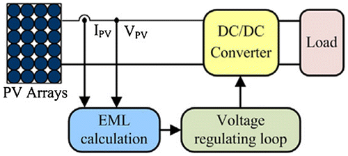
The method is based on artificial intelligence. Brief explanation of ANN structures is presented in Syafaruddin, Karatepe, and Hiyama (Citation2009). The method uses the global MPP voltage as a reference voltage to generate the required control signal for the power converter (Syafaruddin, Karatepe, and Hiyama Citation2009). The ANN is sufficiently accurate in mapping between a PSC and optimum voltage and power of a PV array (Syafaruddin, Karatepe, and Hiyama Citation2009). They need low computation requirement, fast-tracking speed and high static/dynamic tracking efficiencies. Two simple and fast neural network-based MPPT methods suitable for PV systems operating under fast changing environments are proposed by Liu et al. (Citation2013). The structure of the system is presented in Figure .
Figure 9. Block diagram of neural network-based MPPT methods for PV systems operating under fast changing environments (Liu et al. Citation2013).
4.3.4. Genetic algorithm MPPT method
Genetic algorithm (GA) is an optimization technique that resembles natural genetics. Using this technique, an optimal set of parameters is determined based on a “survival of the fittest” principle. In fact, it is an adaptive meta-heuristic search technique that involves generation, systematic evaluation and enhancement of potential design solution until a stopping criterion is met. A GA-based MPPT algorithm approach is developed by Shaiek et al. (Citation2013). They showed that GA method succeeded to overcome the difficulties showed by common methods and reach the global MPP. It successfully tracks the global maximum when multiple peaks exist in the P–V characteristics.
4.4. Novel MPPT methods under PSCs
In recent years, several authors have developed new methods of tracking the MPP under sudden or partial change in insolation. The main advantage of these methods is that they require less number of iterations to converge, independent to the initial conditions. Some of these methods are: the novel ant colony optimization (ACO)-based MPPT method, the multipoint direct estimation method, the new complex MPPT algorithm, the PV array’s output DC/DC converter control method, the MPPT approach with consideration to converter losses, the Power compensation and MPPT control system approach, the global maximum power searching method and the mismatching compensation in PV array for real MPPT.
4.4.1. Novel ACO-based MPPT method
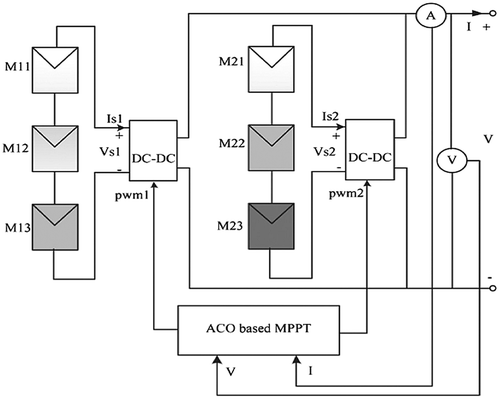
The ACO-based method is a probabilistic algorithm used to find the global optimal solution for a nonlinear problem (Chun et al. Citation2010; Dorigo and Stützle Citation2004; Syafaruddin, Karatepe, and Hiyama Citation2009). This heuristic technique not only ensures the ability to find the global MPP, but also gives a simpler control scheme and lower system cost. It combines a positive feedback mechanism, distributed computing and a greedy search algorithm. It has a strong ability to search the optimal solution. The positive feedback mechanism ensures that the ant colony algorithm is capable of early detection of the optimal solution. Distributed computing helps the ACO-based method to avoid premature convergence while the greedy search helps to quickly find an acceptable solution, thereby enhancing the efficiency of the system. The method requires less number of iterations to converge and it is convergence independent of the initial conditions (Jian, Maskell, and Patra Citation2013). The structure of the ACO control is presented in Figure .
Figure 10. ACO-based MPPT structure (Jian et al. Citation2013).
4.4.2. Multipoint direct-estimation method
Multipoint direct-estimation method directly estimates the multiple MPPs of PV modules under PSC based on the p-n junction semiconductor theory (Wan et al. Citation2012). The method enables to find the accurate MPP of PV modules and to achieve maximum utilization efficiency. A simplified control model to directly estimate the MPP of PV modules with series-connection using the p-n junction semiconductor theory is developed in Wan et al. (Citation2012) and Sze (Citation2006).
4.4.3. New complex MPPT algorithm for PSC
This algorithm improves the original conventional composite MPPT algorithm (i.e. the two stage MPPT control method), adds new calculation parameters and uses a more streamlined and flexible algorithm program tracking the real MPP. In the non-uniform sunlight or rapid change of sunlight conditions, it can quickly and accurately track the MPP and has a quick response and good performance. The method is widely explained in Cui, Yao, and Luo (Citation2012).
4.4.4. PV array’s output DC/DC converter control method
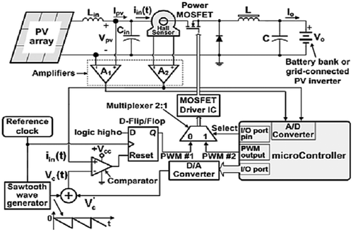
The method is used to determine the global MPPT of a PV generator under PSC. A detailed block diagram of the system is depicted in Figure . Depending on the PV system application domain, a buck-type DC/DC power converter is used to interface the PV array output power to either a battery bank or a DC/AC inverter connected to the electric grid (Kerekes et al. Citation2011; Koutroulis and Blaabjerg Citation2011, Citation2012; Mohan, Undeland, and Robbins Citation1995). The proposed global MPPT procedure performs in three consecutive phases: constant input power, PV array voltage regulation and P&O stage. It can easily be incorporated into any existing MPPT control system in both high nominal-power-rating PV systems and low-power energy harvesting applications.
Figure 11. A detailed block diagram of a global MPPT system (Koutroulis and Blaabjerg Citation2012).
4.4.5. MPPT approach with consideration to converter losses
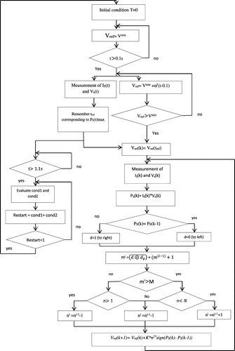
The method operates on the DC/DC converter output power characteristic by including converter losses influence. It tracks the maximum power with the intention of reducing the total losses including those of converters; therefore, MPPT operates considering the output characteristic. A binary condition called “restart” allows detecting a wrong maximum operating point (“restart” passes from “1” to “0”). By this algorithm, an incorrect maximum operating point can be detected using two distinct conditions (Ahmed and Miyatake Citation2008; Ji et al. Citation2009; Reneaudineau et al. 2011). The flow chart of the algorithm is shown in Figure and the method is detailed in Reneaudineau et al. (2011).
4.4.6. Power compensation approach
The control approach is based on recovering the power of non-shaded PV modules from the system by forward biasing a bypass diode of the shaded PV modules. It uses DC–DC converters equipped with each PV string in the PV array. To identify which shaded PV modules should be deactivated, the operating voltage of the PV modules is monitored and compared. The system enables the non-shaded PV modules to operate effectively at their normal MPP. The approach is widely presented by Karatepe et al. (Citation2007, Citation2008) and guarantees obtaining the global maximum power under any partial shading conditions. It can be applied either to non-uniform insolated PV arrays or in the presence of a fault in the array to prevent a reduction in power due to shaded or faulty modules.
4.4.7. Global maximum power searching method
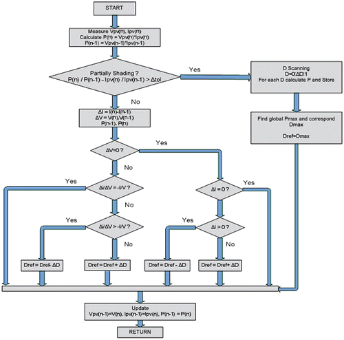
Global maximum power searching method combines InCond as fundamental algorithm and scanning approach method which utilizes duty cycle sweep to track the global maximum when the PV array operates under PSC. The InCond method is a very effective MPPT method when the entire PV array is under the uniform solar irradiance condition. So it should be improved to operate under PSCs. Murat, Sabri, and Birol (Citation2013) proposed a scanning approach in addition to the InCond method to track the global maximum power under PSCs. The flow chart of the method is presented in Figure . It can detect the PSCs and shows the same performance compared to the classical methods. It overcomes the shortcomings of some conventional methods and increases significantly the efficiency of the PV installation under PSCs.
Figure 13. Flow chart of Global maximum power searching method (Murat, Sabri, and Birol Citation2013).
4.4.8. Mismatching compensation in PV array control
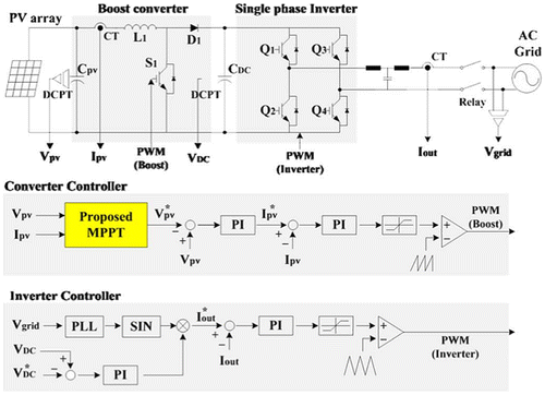
The method is based on the InCond method with step-size variation. When a partial shading condition is detected, the method changes the voltage reference to a linear function. After the movement of the operating point, the MPPT method operates in the same manner as the conventional Inc Cond method in order to find the real MPP. The method is well developed in Hyok Ji et al. (Citation2011) and the system block diagram is presented in Figure .
Figure 14. Block diagram of mismatching compensation in PV array for RMPPT (Ji et al. Citation2009).
4.4.9. Extremum seeking MPPT control approach
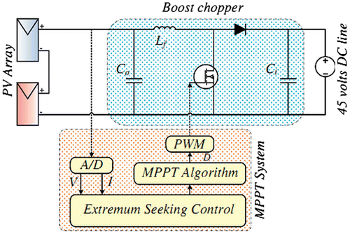
The method is based on analysing the output characteristics of PV array under uniform irradiance and partial shading conditions. The operating principle takes advantage of the conditions for recognition of global MPP. The extremum seeking control (ESC) approach uses a series combination of low pass filter and high pass filter. These two filters act as a band pass filter and let a specific frequency of input power which includes the derivative of PV with respect to its voltage. The method operates on the DC to DC converter based on ECS method without its disadvantages. The approach is widely presented in Doostabab et al. (Citation2013). The block diagram of the method is presented in Figure .
Figure 15. Block diagram of the ESC technique for an MPPT system (Doostabab et al. Citation2013).
4.4.10 New software-based method
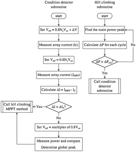
The method is developed in Kouchaki, Iman-Eini, and Asaei (Citation2013) and employs an analytic condition for quick determination of PSCs from normal conditions. It works correctly in both uniform and non-uniform insolation conditions. The flow chart of the method is presented in Figure .
Figure 16. Flow chart of the new software method (Kouchaki, Iman-Eini, and Asaei Citation2013).
5. Discussion
MPPT techniques for PV systems operating under partially shaded insolation condition are important to ensure the operation of the PV generator at its MPP. Various methods and approaches of tracking the MPP from a PV generator operating under these conditions are presented above. However, each method has advantages and drawbacks. In this section, some critical analysis of them are discussed.
Voltage/current-based MPPT methods main advantages are that they use only one feedback loop and their algorithms are easy to implement. However, interrupted system operation yields power losses when scanning the entire control range. Thus, the real power extracted is not considered to be of (from) the panels. Similarly, open-circuit voltage PV test cell method also uses one feedback-loop control, but it is not influenced by the interruptions of the operation of the PV set out in the previous methods. Its algorithm is also easy to implement. Nevertheless, it considers that the test cell has identical properties to each cell of the main PV generator, which is not true in practice (Salas et al. Citation2006).
Curve-fitting method requires accurate knowledge of the physical parameters related to cell’s material and manufacturing specifications (Masoum and Dehbonei Citation1999). Its algorithm requires a large memory capacity for calculation. In the same way, loop-up table method has the disadvantage that a large capacity of memory is required for storage of the data. Moreover, the implementation must be adjusted for a specific PV panel. In addition, it is difficult to record and store all possible system conditions.
Perturbation and observation method is easy to implement. Its main advantage is that there are no oscillations around the MPP in steady state (Mohammad, Saeedeh, and Abdi Citation2013). Its main drawback is the complexity to design its controller. In addition, that method cannot readily track immediate and rapid changes in environmental conditions or partial shading of the PV modules and there are downsides since it cannot always keep the PV system at the MPP due to the slow trial and error process. Nevertheless, the problem is solved by an improved PSO method. Its main advantage is that it reduces the steady-state oscillation (to practically zero) once the MPP is located (Ishaque et al. Citation2014). Recently, Mohammad, Saeedeh, and Abdi (Citation2013) proposed a PSO-based MPPT for PV systems under environmental and PSCs. The performance of the proposed method compared to others like P&O, improved P&O, voltage/current-based MPPT algorithms, especially under PSC is best. The algorithm is simple, easy to implement, fast convergence and can be computed rapidly. It covers the most pertinent details of MPPT and its implementation using a low-cost microcontroller is possible. Key advantage is also the ability to escape from local maxima.
Recently, Kok, Mekhilel, and Azadeh (Citation2013) presented the simulation and hardware implementation of InCond algorithm using buck–boost converter and PIC18F44520 controller. The system showed the capability and functionality to track MPP with a voltage ripple ratio equals to 0.006. The proposed system is efficient, easy to design and low cost. It uses a low-cost PIC controller to sense the PV module’s output voltage and current. Duty cycle of the buck–boost converter is adjusted to keep the PV system operating at the MPP. The buck–boost converter also provided a discontinuous input current and the output voltage is inverted. In addition, their algorithm is fast power tracking but it might be unstable when the solar intensity is low due to the low current differentiation. In addition, Kok and Mekhilel (Citation2014) brought some modifications to the conventional InCond algorithm to mitigate the inaccurate response under fast changing solar irradiation level. They developed the novel algorithm to modulate the duty cycle of the DC–DC converter. The simulation and experimental results showed that the proposed algorithm is able to track the GMPP accurately and thus reduces the power losses faced by the conventional algorithm.
Several papers present other methods like: Differentiation method which requires at least eight calculations and measurements to solve the system of equation, while the two-stage MPPT control presented by Kobayashi, Ichiro, and Yoshio (Citation2006) has simple control process even under rapidly changing non-uniform insolation, and it is quite clear that these operating points agree well with the real peak power point of each condition. On the other hand, the parasitic capacitance method (Salas et al. Citation2006) requires two multiplications with the following complexity of the control circuit, while the only current PV method’s major advantage is that it operates successfully even in cases of rapidly changing atmospheric conditions and different sky conditions. Forced oscillation method successfully analyses the amplitude and the phase to provide information on the location of the MPP. Nevertheless, its disadvantage is the complexity of its simple implementation as well as the evaluation of the signals is low.
According to the direct algorithms discussed above, one can thus conclude that, the PSO and modified Incremental methods have better convergence compared to the others.
Chia et al. (Citation2012) developed a fuzzy logic-based MPPT (FMPPT). The method enables to reduce tracking time and voltage fluctuation as high as 31.3–60% compared to MPPT with 1.0 V perturbation size. This method is able to function properly even without precise inputs. Fuzzy logic is relatively more robust compared to the conventional nonlinear controller. When the PV system is approaching MPP, it will select small perturbation size of voltage to minimize the fluctuation around MPP. In addition, it can control the PV system to operate at a more precise operating voltage. FMPPT is able to reduce the oscillation of the operating voltage thus maintaining the power stability of the PV array when the MPP has been successfully identified. Similarly, the FLS method was developed and enables intuitive adjustment of control parameters and fast response. Fibonacci search algorithm is commonly used as a MPPT method. However, it fails to track MPP during PSCs and needs a powerful processor. Balaji, Mathur, and Ramaprabha (Citation2012) have modified the Fibonacci search algorithm to find the MPP under PSCs. ANN method involves intuitive decision of users to determine the best network structure. The main advantages of ANN method are (Liu et al. Citation2013):
| • | Tracking speed is fast due to the utilization of high-speed voltage regulation loop, resulting high dynamic MPPT efficiency. | ||||
| • | They are very simple and require only few multiplication and addition operations; hence, implementation using low-cost achievable. | ||||
| • | The static MPPT efficiencies are very high because, at steady state, there are no oscillations around the MPP. | ||||
| • | They can be applied to all types of power converters, and can easily be integrated into any type of voltage regulation loop. | ||||
| • | Using ANN model, the PV Generation System user can apply the developed MPPT controller to any PV panel without the need to modify the firmware of the PGS. | ||||
Jian, Maskell, and Patra (Citation2013) presented a novel ACO method and demonstrated the accuracy of the method by two experiments: the first experiment demonstrated the ability of the ACO-based MPPT to track the global MPP under steady and transient shading patterns and the second compared ACO-based MPPT algorithm with other existing MPPT technique. This method combines a positive feedback mechanism, distributed computing and a greedy search algorithm. It has a strong ability to search the optimal solution. The positive feedback mechanism ensures that the ant colony algorithm is capable of early detection of the optimal solution. Distributed computing helps the ACO to avoid premature convergence. The greedy search helps to quickly find an acceptable solution, thereby enhancing the efficiency of the system. Its performance compared to other traditional MPPT techniques, such as constant voltage tracking, P&O, PSO is better.
Multipoint direct estimation method developed by Wan et al. (Citation2012) uses a simplified control model to directly estimate the MPP of PV modules with series connection using the p–n junction semiconductor theory. The method is effective, quick and the global MPP can be located within milliseconds of charging time of the capacitor, while the new complex MPPT algorithm for PSC has a quick response and good performance. The design can be applied to the LED lighting of PV system very conveniently and efficiently, and it also contributes to the socio-economic and environmental protection.
Koutroulis and Blaabjerg (Citation2012) developed a new method to track the GMPP based on controlling a DC/DC converter connected at the PV array. The experimental results verify that the proposed global MPP method guarantees convergence to the GMPP under any PSCs. This method can be applied in either stand-alone or grid-connected PV systems comprising PV arrays with unknown electrical characteristics and does not require knowledge about the PV modules configuration within the PV array. Nguyen and Low (Citation2010) proposed global MPPT based on the direct search algorithm. This method guarantees convergence to the global MPP under any partial shading conditions. Compared to other methods, the global MPPT process is accomplished after less PV array power perturbation steps, while the new approach in tracking maximum power under PSCs with consideration to converter losses allows better performances under PSC by increasing the efficiency and reducing losses through the converter. The real maximum power point tracking (RMPPT) method proposed by Ji et al. (Citation2009) allocates the global MPP when the PV array experiences PSC. In fact, when the PV array is under PSC, the PV characteristic will become more complex with the occurrence of multiple MPPs. PV array which operates at the trapped local MPP will generate limited power but the PV array is capable to generate higher output power. For a PV array that generates less power, the efficiency of the system is reduced.
As it could be seen from the above literature review, various methods of MPPT under PSC have been developed in the past. They vary in complexity, sensors requirements, convergence speed, cost, implementations, range of effectiveness, hardware implementation and popularity. For a given condition, the choice of the algorithm to track MPP depends on the objectives and available data and resources. However, according to the previous discussion, it appears that artificial intelligence and novel methods seem to be better to track the MPP.
Table presents a Summary of strengths and weakens of each method.
Table 1. Summary of strengths and weakens of each method.
6. Conclusion
In this paper, various methods of tracking the MPP in partially shaded or rapidly changing insolation conditions have been classified into four main groups and developed:
| • | Indirect methods have the particular feature of not obtaining, but rather estimating the maximum power for a given irradiance or temperature. In many cases, they can be simple, inexpensive and not totally versatile with respect to load profile. They are not able to obtain the MPP exactly from a PV system in any atmospheric conditions. | ||||
| • | Direct methods offer the advantages that neither a large database nor a large memory is necessary for calculating the MPP. They are totally versatile with respect to the load profile and the seeking of MPP is independent to the variation of the parameters of the PV generator. | ||||
| • | Artificial intelligence methods do not need exact mathematical models; they can work with vague inputs and, in addition; they can handle nonlinearities and are adaptive, in nature; likewise, their control gives them robust performance under parameter variation, load and supply voltage disturbances. They are sufficiently accurate in mapping between a PSC and optimum voltage and power of a PV array. More power can be extracted and the overall energy yield can be increased from lightly to heavily PSCs. | ||||
| • | Novel methods compared to some traditional MPPT methods, such as indirect and direct methods, provide better performance to find the global MP under various shading conditions. For instance, they required less number of iterations to converge and are convergence independent to the initial conditions. | ||||
Disclosure statement
No potential conflict of interest was reported by the authors.
References
- Abdalla, I., J. Corda, and L. Zhang. 2013. “Multilevel DC-link Inverter and Control Algorithm to Overcome the PV Partial Shading.” IEEE Transactions on Power Electronics 28 (1): 14–18.10.1109/TPEL.2012.2209460
- Ahmed, N. A., and M. Miyatake. 2008. “A Novel Maximum Power Point Tracking for Photovoltaic Applications under Partially Shaded Insolation Conditions.” Electric Power Systems Research 78 (5): 777–784.10.1016/j.epsr.2007.05.026
- Al-Atrash, H., I. Batarseh, and K. Rustom. 2005. “Statistical Modeling of DSP-based Hill-climbing MPPT Algorithms in Noisy Environments.” In Applied Power Electronics Conference and Exposition, APEC 2005, Twentieth Annual IEEE, Vol. 3: 1773–1777.
- Balaji, M., B. L. Mathur, and R. Ramaprabha. 2012. “Maximum Power Point Tracking of Partially Shaded Solar PV System Using Modified Fibonacci Search Method with Fuzzy Controller.” Electrical Power and Energy Systems 43: 754–765.
- Bavaro, L. T. W., and J. W. Bates. 1988. Power Regulator Utilizing Only Battery Current Monitoring. US Patent 4794272.
- Branbrilla, A., M. Gambarara, A. Garutti, and F. Ronchi. 1999. “New Approach to photovoltaic Arrays Maximum Power Point Tracking.” In 30th Annual IEEE Power Electronics Specialists Conference, Vol. 2: 632–637.
- Chia, S. C., C. Yit Kwong, L. C. Bih, A. Kiring, and K. T. K. Teo. 2012. “Fuzzy Logic Based MPPT for PV Ray Under Partially Shaded Condition.” In 2012 International Conference on Advanced Computer Science Applications and Technologies (ACSAT): 133–138. doi:10.1109/ACSAT.2012.46.
- Chia, S. C., P. Neelakantan, S. Y. Hou Soo, and K. T. K. Teo. 2011. “Maximum Power Point Tracking for PV Array under Partially Shaded Conditions.” In 2011 Third International Conference on Computational Intelligence, Communication Systems and Networks (CICSyN): 72–77. doi:10.1109/CICSyN.2011.27.
- Chun, W. N., S. Zuo, K. Yukita, Y. Goto, and K. Ichiyanagi. 2010. “Research of PV Model and MPPT Methods in Matlab.” Power and Energy Engineering Conference 2: 50–55.
- Cocconi, A., and W. Rippel. 1990. Lectures from GM Sunracer Case History, Lecture 3–1: The Sunracer Power Systems. Number M-101. Warderendale, PA: Society of Automotive Engineers.
- Cui, Y., Wen Yao, and Jinzhao Luo. 2012. “A Research and Improvement on a Maximum Power Point Tracking Method for PV System under Partially Shaded Conditions.” Procedia Engineering 29: 2583–2589.10.1016/j.proeng.2012.01.355
- David, J. H. 1968. Power Conditioning System. US Grant US3384806 A.
- Doostabab, H. H., R. Keypour, M. R. Khalghani, and M. H. Khooban. 2013. “A New Approach in MPPT for Photovoltaic Array Based on Extremum Seeking Control under Uniform and Non-uniform Irradiances.” Solar Energy 94: 28–36.
- Dorigo, M., and T. Stützle. 2004. Ant Colony Optimization. Cambridge, MA: MIT Press.10.1007/b99492
- El-Shafy, A. A. N., H. F. Faten, and E. M. Abou El-Zahab. 2003. “Evaluation of a Proper Controller Performance for Maximum-power Point Tracking of a Stand-alone PV System, Solar Energy Mater.” Solar Cells 75 (3–4): 723–728.
- Ghoddami, H., and A. Yazdani. 2011. “A Single-stage Three-phase Photovoltaic System with Enhanced Maximum Power Point Tracking Capability and Increased Power Rating.” IEEE Transactions on Power Delivery 26 (2): 1017–1029.10.1109/TPWRD.2010.2055896
- Hinchey, M. G., R. Sterritt, and C. Rouff. 2007. “Swarms and Swarm Intelligence.” Computer 40 (4): 111–113.10.1109/MC.2007.144
- Hiyama, T., and K. Kitabayashi. 1997. “Neural Network Based Estimation of Maximum Power Generation from PV Module Using Environmental Information.” IEEE Transactions on Energy Conversion 12 (3): 241–247.10.1109/60.629709
- Hiyama, T., S. Kouzuma, and T. Imakubo. 1995. “Identification of Optimal Operating Point of PV Modules Using Neural Network for Real Time Maximum Power Tracking Control.” IEEE Transactions on Energy Conversion 10 (2): 360–367.10.1109/60.391904
- Hussein, K. H., I. Muta, T. Hoshino, and M. Osakada. 1995. “Maximum Photovoltaic Power Tracking: An Algorithm for Rapidly Changing Atmospheric Conditions.” IEE Proceedings - Generation, Transmission and Distribution 142 (1): 59–64.10.1049/ip-gtd:19951577
- Hyok Ji, Y., J. Doo-Yong, K. Jun-Gu, K. Jae-Hyung Tae, L. Won, and W. Chung-Yuen. 2011. “A Real Maximum Power Point Tracking Method for Mismatching Compensation in PV Array under Partially Shaded Conditions.” EEE Transactions on Power Electronics 26 (4): 1001–1009.
- Ibrahim, S. A., F. F. Houssiny, H. M. Z. El-Din, and M. A. El-Shibini. 1999. “Microcomputer Controlled Buck Regulator for Maximum Power Point Tracker for DC Pumping System Operates from Photovoltaic System.” In 1999 IEEE International Fuzzy Systems Conference Proceedings, 22–25 August, Vol. 1: 406–411.
- Ishaque, K., Z. Salam, M. Amjad, and S. Mekhilef. 2014. “An Improved Particle Swarm Optimization PSO-based MPPT for PV with Reduce Steady-state Oscillation.” IEE Transaction on Industrial Electronic 61 (10).
- Ji, Y. H., D. Y. Jung, C. Y. Won, B. K. Lee, and J. W. Kim. 2009. “Maximum Power Point Tracking Method for PV Array Under Partially Shaded Condition.” In IEEE Energy Conversion Congress and Exposition.
- Jian, L. L., Douglas L. Maskell, and Jagdish C. Patra. 2013. “A Novel Ant Colony Optimization-based Maximum Power Point Tracking for Photovoltaic Systems under Partially Shaded Conditions.” Energy and Buildings 58: 227–236.
- Karatepe, E., T. Hiyama, M. Boztepe, M. Çolak. 2007. “Power Controller Design for Photovoltaic Generation System under Partially Shaded Insolation Conditions.” In IEEE 2007 International Conference on Intelligent Systems Applications to Power Systems.
- Karatepe, E., T. Hiyama, M. Boztepe, and M. Çolak. 2008. “Voltage Based Power Compensation System for Photovoltaic Generation System under Partially Shaded Insolation Conditions.” Energy Conversion and Management 49: 2307–2316.10.1016/j.enconman.2008.01.012
- Kennedy, J., and R. C. Eberhart. 1995. “Particle Swarm Optimization.” In Proceeding of the IEEE International Conference on Neural Networks, Vol. 4: 1942–1948.10.1109/ICNN.1995.488968
- Kerekes, T., R. Teodorescu, P. Rodriguez, G. Vazquez, and E. Aldabas. 2011. “A New High-efficiency Single-phase Transformerless PV Inverter Topology.” IEEE Transactions on Industrial Electronics 58 (1): 184–191.10.1109/TIE.2009.2024092
- Kim, Y., H. Jo, and D. Kim. 1996. “A New Peak Power Tracker for Cost-effective Photovoltaic Power Systems.” In IEEE Proc. Energy Conversion Engineering Conference. IECEC 96: vol. 3: 1673–1678.
- Kobayashi, K., T. Ichiro, and S. Yoshio. 2006. “A Study of a Two-stage Maximum Power Point Tracking Control of a Photovoltaic System under Partially Shaded Insolation Conditions.” Solar Energy Materials & Solar Cells 90: 2975–2988.
- Kok, S. T., and Saad Mekhilel. 2014. “Modified Incremental Conductance MPPT Algorithm to Mitigate Inaccurate Responses under Fast-changing Solar Irradiation Level.” Solar Energy 101: 33–342.
- Kok, S. T., Saad Mekhilel, and S. Azadeh. 2013. “Simple and Low Cost Incremental Conductance Maximun Power Point Tracking Using Buck-Bosster Converter.” Journal of Renewable and Sustainable Energy. doi:10.1063/1.4794749.
- Kouchaki, A., Hossein Iman-Eini, and Behzad Asaei. 2013. “A New Maximum Power Point Tracking Strategy for PV Arrays under Uniform and Non-uniform Insolation Conditions.” Solar Energy 91: 221–232.10.1016/j.solener.2013.01.009
- Koutroulis, E., and F. Blaabjerg. 2011. “Design Optimization of Grid-connected PV Inverters.” In 26th Annual IEEE Applied Power Electronics Conference and Exposition (APEC): 691–698.
- Koutroulis, E., and F. Blaabjerg. 2012. “A New Technique for Tracking the Global Maximum Power Point of PV Arrays Operating under Partial-shading Conditions.” IEEE Journal of Photovoltaics 2: 184–190.10.1109/JPHOTOV.2012.2183578
- Liu, Y. H., Chun-Liang Liu, Jia-Wei Huang, and Jing-Hsiau Chen. 2013. “Neural-network-based Maximum Power Point Tracking Methods for Photovoltaic Systems Operating under Fast Changing Environments.” Solar Energy 89: 42–53.10.1016/j.solener.2012.11.017
- Liu, Y. H., H. Shyh-Ching, H. Jia-Wei, and L. Wen-Cheng. 2012. “A Particle Swarm Optimization-based Maximum Power Point Tracking Algorithm for PV Systems Operating Under Partially Shaded Conditions.” IEEE Transactions on Energy Conversion 27 (4).
- Louis, A. U. 1972. System for Detecting and Utilizing the Maximum Available Power from Solar Cells. US Patent 3,696,286.
- Mäki, A., and S. Valkealahti. 2012. “Power Losses in Long String and Parallel-connected Short Strings of Series-connected Silicon-based Photovoltaic Modules due to Partial Shading Conditions.” IEEE Transactions on Energy Conversion 27: 173–183.10.1109/TEC.2011.2175928
- Masoum, M. A. S., and H. Dehbonei 1998. “Optimal Power Point Tracking of Photovoltaic System under All Operating Conditions.” In 17th Congress of the World Energy Council, Houston, TX.
- Masoum, M. A. S., and H. Dehbonei. 1999. “Design, Construction and Testing of a Voltage-based Maximum Power Point Tracker (VMPPT) for Small Satellite Power Supply.” In 13th Annual AIAA/USU Conference, Small Satellite.
- Mohammad, S., A. Saeedeh, and Shirzad Abdi. 2013. “A PSO-based Maximum Power Point for Photovoltaic System Under Environmental and Partially Shaded Conditions. doi:10.1002/pip.2416.
- Mohan, N., T. Undeland, and W. Robbins. 1995. Power Electronics: Converters, Applications and Design. 2nd ed., 164–172. Wiley.
- Moreno, F., J. Muňoz, and E. Lorenzo. 2010. “Experimental Model to Estimate Shading Losses on PV Arrays.” Solar Energy Materials & Solar Cells 94: 2298–2303.
- Murat, Ü., Ç. Sabri, and A. Birol. 2013. “A New Maximum Power Point Tracking Method for PV Systems under Partially Shaded Conditions.” In 4th International Conference on Power Engineering, Energy and Electrical Drives, Istanbul, Turkey, 13–17 May. 978-1-4673-6392-1/13/$31.00 ©2013 IEEE
- Nguyen, T. L., and K. S. Low. 2010. “A Global Maximum Power Point Tracking Scheme Employing DIRECT Search Algorithm for Photovoltaic Systems.” IEEE Transactions on Industrial Electronics 57 (10): 3456–3467.10.1109/TIE.2009.2039450
- Noguchi, T., S. Togashi, and R. Nakamoto. 2002. “Short-current Pulse-based Adaptive Maximum Power Point Tracking for a Photovoltaic Power Generation System.” In Proceedings of the 2000 IEEE International Symposium on Industrial Electronics, Vol. 1: 157–162.
- Patcharaprakiti, N., S. Premrudeepreechacharn, and Y. Sriuthaisiriwong. 2005. “Maximum Power Point Tracking Using Adaptive Fuzzy Logic Control for Grid-connected Photovoltaic System.” Renewable Energy 30 (11): 1771–1788.10.1016/j.renene.2004.11.018
- Pilawa-Podgurski, R. C. N., and D. J. Perreault. 2013. “Submodule Integrated Distributed Maximum Power Point Tracking for Solar Photovoltaic Applications.” IEEE Transactions on Power Electronics 28: 2957–2967.10.1109/TPEL.2012.2220861
- Poponi, D. 2003. “Analysis of Diffusion Paths for Photovoltaic Technology Based on Experience Curves.” Solar Energy 74: 331–340.10.1016/S0038-092X(03)00151-8
- Rodrigo, P., Eduardo F. Fernández, F. Almonacid, P. J. Pérez-Higueras, and H. Perez. 2013. “A Simple Accurate Model for the Calculation of Shading Power Losses in Photovoltaic Generators.” Solar Energy 93: 322–333.10.1016/j.solener.2013.04.009
- Salam, Z., A. Shamsudin, M. Amjad, and K. Ishaque. 2012. “A Direct Control Based Maximum Power Point Tracking Method for Photovoltaic System under Partial Shading Conditions Using Particle Swarm Optimization Algorithm.” Applied Energy 99: 414–422.
- Salameh, Z., and D. Taylor. 1990. “Step-up Maximum Power Point Tracker for Photovoltaic Arrays.” Solar Energy 44 (1): 57–61.10.1016/0038-092X(90)90027-A
- Salas, V., E. Olías, A. Barrado, and A. Lázaro. 2006. “Review of the Maximum Power Point Tracking Algorithms for Stand-alone Photovoltaic Systems.” Solar Energy Materials and Solar Cells 90: 1555–1578.10.1016/j.solmat.2005.10.023
- Shenoy, P. S., K. A. Kim, B. B. Johnson, and P. T. Krein. 2013. “Differential Power Processing for Increased Energy Production and Reliability of Photovoltaic Systems.” IEEE Transactions on Power Electronics 28: 2968–2979.10.1109/TPEL.2012.2211082
- Schoeman, J. J., and J. D. Van. 1982. “A Simplified Maximal Power Controller for Terrestrial Photovoltaic Panel Arrays.” In IEEE Power Electronics Specialists Conference: PESC ‘82 Record, New York: 361–367.
- Shaiek, Y., Mouna Ben Smida, Anis Sakly, and Mohamed Faouzi Mimouni. 2013. “Comparison between Conventional Methods and GA Approach for Maximum Power Point Tracking of Shaded Solar PV Generators.” Solar Energy 90: 107–122.10.1016/j.solener.2013.01.005
- Shimizu, T., M. Hirakata, T. Kamezawa, and H. Watanabe. 2001. “Generation Control Circuit for Photovoltaic Modules.” IEEE Transactions on Power Electronics 16 (3): 293–300.10.1109/63.923760
- Silvestre, S., A. Boronat, and A. Chouder. 2009. “Study of Bypass Diodes Configuration on PV Modules.” Applied Energy 86: 1632–1640.10.1016/j.apenergy.2009.01.020
- Sun, X., W. Wu, X. Li, and Q. Zhao. 2002. “A Research on Photovoltaic Energy Controlling System with Maximum Power Point Tracking.” In Proceedings of the Power Conversion Conference, Vol. II, No. D6-3, PCC-Osaka, 2–5 April: 822–826.
- Syafaruddin, E. Karatepe, and T. Hiyama. 2009. “Artificial Neural Network-polar Coordinated Fuzzy Controller Based Maximum Power Point Tracking Control under Partially Shaded Conditions.” IET Renewable Power Generation 3 (2): 239–253.10.1049/iet-rpg:20080065
- Syafaruddin, E. Karatepe, and T. Hiyama. 2012. “Performance Enhancement of Photovoltaic Array through String and Central Based MPPT System under Non-uniform Irradiance Conditions.” Energy Conversion and Management 62: 131–140.10.1016/j.enconman.2012.03.028
- Sze, S. M. 2006. Physics of Semiconductor Devices. 3rd ed. New York: Wiley.10.1002/0470068329
- Takehara, N., and S. Kurokami. 1997. Power Control Apparatus and Method and Power Generating System Using Them. US Patent 5,654,883.
- Teulings, W. J. A., J. C. Marpinard, and A. Capel. 1993. “A Maximum Power Point Tracker for a Regulated Power Bus.” In Proceedings of the European Space Conference.
- Tse, K. K., H. S. H. Chung, S. Y. R. Hui, and M. T. Ho. 2001. “A Novel Maximum Power Point Tracking Technique for PV Panels.” In IEEE Power Electronics Specialists Conference, 2001, PESC. IEEE, Vol. 4: 1970–1975.
- Veerachary, M., T. Senjyu, and K. Uezato. 2003. “Neural-network-based Maximum-power-point Tracking of Coupled-inductor Interleaved-boost-converter-supplied PV System Using Fuzzy Controller.” IEEE Transactions on Industrial Electronics 50 (4): 749–758.10.1109/TIE.2003.814762
- Velasco-Quesada, G., and F. Guinjoan-Gispert. 2009. “Electrical PV Array Reconfiguration Strategy for Energy Extraction Improvement in Grid-connected PV Systems.” IEEE Transactions on Industrial Electronics 56: 4319–4331.10.1109/TIE.2009.2024664
- Wan, J. C., L. S. Yu, C. K. Kun, C. S. Jyh, and A. J. Joe. 2012. “A Novel Multipoint Direct-estimation Method for the Maximum Power Point Tracking of Photovoltaic Modules under Partially Shaded Irradiation Conditions.” In 2nd IEEE ENERGYCON Conference & Exhibition, 2012/Advances in Energy Conversion Symposium. 978-1-4673-1454-1/12/$31.00 © 2013 IEEE.
- Wilamowski, B. M. 2001. “Microprocessor Implementation of Fuzzy System and Neural Networks.” In International Joint Conference on Neural Networks, Vol. 1: 234–239.
- Won, C., H. Kim, W. Kim, S. Kim, and H. S Kim. 1994. “A New Maximum Power Point Tracker of Photovoltaic Arrays using Fuzzy Controller.” In 25th Annual IEEE Power Electronics Specialists Conference, PESC 94 Record, Vol. 1: 396–403.

