ABSTRACT
Development of waste heat-driven absorption-based cooling system is inspired for the need of removing high heat flux from the sustainable data centre environment. This paper presents a simulation study of single-stage Lithium Bromide–Water (LiBr–H2O) vapour absorption heat pump for chip cooling. In the present work, a complete thermodynamic analysis of the single-stage LiBr–H2O vapour absorption-based heat pump for chip cooling without a solution heat exchanger is performed and a user friendly graphical user interface (GUI) package including visual components is developed by using MATlab (2008b). The effect of chip heat flux on COP (Coefficient of Performance), flow rates and conductance is examined using the developed package. The model is verified using the data available in the literature which indicates that there is a greater reduction in the absorber load. The influence of chip heat flux on the performance and thermal loads of individual components are studied, and it is concluded that COP decreases from 0.7121 to 0.68924 with increase in chip heat flux.
1. Introduction
The worldwide energy crisis and the need for cooling, refrigeration and air-conditioning are growing at rapid rate. The worldwide energy consumption is rapidly increasing and it is been estimated that it may reach more than 40% by 2035 (Chevron Citation2014; Rahimifard et al. Citation2014). Cooling requirements are found to be straightaway to the people’s luxury needs. The International Institute of Refrigeration in Paris has projected that about 15% of the electricity generated in the whole world is utilised for refrigeration and air-conditioning processes of different types, and the energy intake for air-conditioning systems has been predicted to be 45% by domestic and commercial buildings (Fan et al. Citation2007).The advanced living style and working standards, the tough outdoor conditions in urban environments and decreased costs of air-conditioning units have resulted in considerable rise in demand for air conditioning in buildings, even in the worst requirement. The rapid growth in air conditioning has enforced a considerable rise in demand for primary energy. Computer room air conditioner, known as CRAC unit, is used for cooling data centres. These air conditioning systems are enormously found in data centres for many decades. The development in the data centre industry, together with the growing power density of server modules, the power consumption by data centre is projected to increase over the coming years. The yearly rise in data centre power demand is estimated to be 15–20% as suggested by the industries (Fan et al. Citation2007). The data centre industries are consuming 1.1–1.5% world’s overall electricity. These industries consume 40–50% of electric power for the IT equipment; 30–40% is used by cooling system and the rest is utilised for power conversion, distribution units and lighting (Brunschwiler et al. Citation2009; Brown et al. Citation2008; Iyengar and Schmidt Citation2009; Nozaki Citation2009). Maximum energy used up by the IT equipment is changed to unwanted heat energy. The amount of consumed electricity in the data centre is turned into waste heat energy; the similar quantity of energy is essential to run data centres cooling system and eliminate that waste heat from server modules. The server consists of several IC chips of different power density levels. Due to the recent advancement in ICs, there is a rapid growth in power density level. These IC chips working under unsympathetic conditions having high heat flux of 100 W/cm2 at junction temperature of more than 100 °C. The traditionally used air cooling method is showing incapable in extracting high heat flux from the chip and to maintain at ambient temperature. As a result, many thermal engineers have proposed to find the new solution to this problem. There is a need for developing innovative methodologies by which these high heat fluxes can be extracted from silicon-based devices.
In this context, a number of researchers have developed active and passive cooling methods for device cooling. In active cooling system, circulation of working fluid is by means of a pump or a compressor which improves the performance of the system but in passive cooling, working fluid is circulated by means of gravitational force or capillary method. Tuckerman and Pease (Citation1981) have shown the new method for cooling chips by having a single-row micro-channel etched directly into the back of a silicon wafer, and maximum power density of 790 W/m2 K is eliminated with an increase in water temperature to 71 K at a pressure of drop 2 bar.
Pal et al. (Citation2002) have developed thermosyphon method for chip cooling using water as a working fluid at average junction-to-ambient thermal resistance of 0.95 kW−1 and obtained maximum cooling capacity of 80 W. Lu et al. (Citation2012) have experimentally studied the copper-based microchannel heat exchangers which are used in heat absorption modules, heat rejection modules and recirculating-liquid cooling system. The experimental results have shown that microchannel liquid flow through individual fins enhances the heat transfer performance, and copper based microchannel heat exchangers have shown advantages in eliminating high heat flux below restricted space. Bintoro et al. (Citation2005) have studied jet impinging technique using water as working fluid and obtained a maximum cooling capacity of 200 W with maximum junction temperature of 90 °C.
Maydanik et al. (Citation2005) have developed loop heat pipe for chip cooling using water and ammonia are the two working fluids, and a maximum cooling capacity of 130 W at minimum junction-to-ambient thermal resistance of 0.58 kW−1 is achieved. Jiang et al. (Citation2002) have performed experimental investigation on electro-osmotic pumping using water as working fluid with maximum cooling capacity of 38 W with junction temperature lower than 120 °C and junction-to-ambient thermal resistance of 2.5 kW−1. Fan et al. (Citation2001) have constructed thermoelectric micro-cooler with maximum cooling power density of 1 kWcm−2. Tan and Tso (Citation2004) have performed experimental investigation for cooling of mobile electronic devices using phase change materials (PCMs) as n-eicosane which maintain the chip temperature at 50 °C, but Hewitt et al. (Citation2010) have reviewed the PCMs for latent heat thermal energy storage systems and described the problems in formulating the system. Few works have been contributed by using active cooling. In active cooling (Refrigeration/heat pump), compressor is used to drive the system. This provides foundation for developing negative thermal resistance in the heat flow path because of the use of compressor. Mongia et al. (Citation2006) have carried experimental study on vapour compression system at laboratory level using Isobutane as a refrigerant with maximum cooling capacity of 50 W at junction-to-ambient thermal resistance of 0.25 K W−1 and Coefficient of Performance (COP) of 2.25.
Trutassanawin et al. (Citation2006) have performed experimental investigation on miniature-scale vapour compression refrigeration systems for cooling electronic devices having capacities of 121–268 W for the pressure ratios of 1.9–3.2 and COP of 2.8–4.7.The conventional vapour compression refrigeration systems need more mechanical energy as the driving cause for the emission of CO2 and the other green house gases such as HFCs and CFCs. These are considered main reasons for ozone layer depletion.
Attention on absorption heat pump (AHP) systems rapidly increased due to the oil crisis in the 1970s which created interest on energy shortage and then in 1990s because of green house effect related to the utilisation of hydro chlorofluro carbons (HCFCs) and Chlorofluro carbons (CFCs) as the refrigerants. Furthermore, with the rise in worldwide energy consumption, it is becoming inevitable to determine the ways of using energy resources effectively. Hence, machines which are driven by low-grade energy sources like waste-heat from chip, solar thermal energy, geothermal energy and industrial wastes can be an interesting alternative for a wiser sustainable energy management. In addition to that, it offers some advantageous features such as simple control, absence of vibration, and low operational price. The major highlight of AR is that its working fluids fulfil the Montreal Protocol on ozone layer depletion and the Kyoto Protocol on global warming. The use of low-grade energy by the absorption units doesn’t lead to any difficulties of emission of green house gases. Absorption-based refrigerator is simple and is adaptable for small, medium or large systems. The AHP system can be used in hot regions mainly where no electricity is available.
In recent years, a number of experimental and theoretical studies on the AHP system have been reported. Chiriac and Chiriac (Citation2010) has developed analytical model using water–ammonia solution as working pair for microelectronic cooling and obtained maximum COP of 0.73. Yoo Jo Kim et al. (Citation2008) have carried out theoretical study of an absorption based heat pump system for device cooling using LiBr–H2O as working pair having maximum cooling capacity of 100 W and COP of 0.87. Ebrahimi et al. (Citation2015) have explained technical and economic problems of absorption cooling machines which are used in data centres. The study has concentrated on development of innovative configuration by placing generator in place of condenser on the chip cooling circuit. The simulation was performed for both absorption pairs such as LiBr–water and water–ammonia. The LiBr–water absorption system has shown best system for data centre/server operating conditions. The work proposes that there is a need of sensitivity analysis for these types of systems.
LiBr–H2O absorption pair has shown promising pair in extracting high latent heat, and has proved eco-friendly since water is used as a refrigerant. For the last five decades, numerous experimental investigations were performed on LiBr–H2O heat pump systems by many investigators. These experimental investigations have mainly contributed to improve the performance of the system or to identify the critical parameters that affect the performance.
Mostafavi and Agnew (Citation1996) have investigated the effect of ambient temperature on the generator temperature, concentration of strong solution, flow ratio of the solution and on the evaporator temperature for LiBr–H2O absorption unit. Yoon et al. (Citation2003) have performed experimental investigation on double-effect LiBr–H2O absorption cycle. Asdrubali and Grignaffini (Citation2005) and Aphornratana and Sriveerakul (Citation2007) have experimentally performed investigation on the performance of an absorption chiller with a cooling capacity of 2 kW. The results have indicated that the performance of the system increases with the increase of the generator and evaporator inlet temperature. The performance of the chiller drops with the rise in the condenser and absorber inlet temperatures.
Marc et al. (Citation2010) and Pongtornkulpanich et al. (Citation2008) have studied the performance of a solar-absorption A/C system with a cooling capacity of 10 kW operating in Italy. Melograno et al. (Citation2009) have constructed an experimental check facility capable of gathering performance curves from an absorption chiller with cooling capacity up to 20 kW. Agyenim et al. (Citation2010) have performed test on the solar-absorption A/C systems of capacity 4.5 kW. The results have shown the average COP of 0.48 for an average peak solar insolation of 812 W/m2. The performance data for specific operating conditions are also charted.
Number of literatures is available related to the development of simulation models to estimate the performance of LiBr–H2O at diverse operating conditions and for different applications. Joudi and Lafta (Citation2001) have performed a steady state computer simulation model in order to evaluate the effect of several operating conditions on the function of each component and to determine the performance of an absorption refrigeration system using LiBr–H2O as a working pair. Grossman and Zaltash (Citation2001) have constructed a computer code ABSIM (Absorption Simulation) for the simulation of absorption systems in a flexible and modular form making it likely to examine many cycle configurations with different working fluids.
Alva and Gonzalez (Citation2002) and Atmaca and Yigit (Citation2003) have constructed the mathematical model for the absorption chiller with a capacity of 10.5 kW to determine the performance characteristics of the system. Florides et al. (Citation2003) have prepared the mathematical model based on energy balance equations written for the absorber, condenser, evaporator and generator for an absorption cooling capacity of 1 kW. Mehrabian et al. (Citation2005) have studied thermodynamic analysis of a single effect absorption chiller using LiBr–H2O solution as working fluid by developing computer program.
In current years, there is a greater attention in applying the principles of second law of thermodynamics for evaluating and assessing the thermodynamic performance of LiBr–H2O system. Talbi and Agnew (Citation2000) have studied exergy analysis on a single-effect absorption refrigeration cycle using LiBr–H2O as the working fluid pair. Lee and Sherif (Citation2000) have performed the second law analysis of a single effect LiBr–H2O absorption refrigeration system. The influence of heat source temperature on COP and exergetic efficiency has been evaluated. Martinez and Pinazo (Citation2002) applied the statistical tool to find the effect of variation of heat exchanger areas on the performance of a single effect machine. Sencana et al. (Citation2005) have studied the exergy losses in each component of a single stage LiBr–H2O absorption system. The comparison of exergy losses in generator and absorber with the evaporator and condenser has been performed. The exergetic efficiency of the system tends to decrease with rise in heat source temperature for both cooling and heating applications. Sedighi et al. (Citation2007) have studied the exergy analysis of a single-effect LiBr–H2O absorption refrigeration system.
The exergy analysis has been performed by considering the mass and energy conservation based on the first and second laws of thermodynamics. The results have indicated that, a decrease in cooling water temperature causes an enhancement in the COP and Exergetic Coefficient of Performance (ECOP). Rising the evaporator temperature also improves the COP, but it causes a decrease in the ECOP of the system. The literature reviews of the authors likeParise et al. (Citation1988), Yang and Guo (Citation1987), Atilgan and Aygun (Citation2014), Agrawal et al. (Citation2015), Karno and Ajib (Citation2008) and Iranmanesh and Mehrabian (Citation2012), Morsy El-Gohary (Citation2013) have shown the studies on LiBr–H2O AHP with respect to development, modification of the cycle, alternate working pair and simulation used for different applications coupled to different energy sources.
Perusal of literature has shown no work has yet been made to investigate the performance of LiBr–H2O-based AHP for chip cooling. The aim of the current work is to study the performance of LiBr–H2O based AHP especially for chip cooling. The steady state simulation (analytical) model is developed to analyse the influence of chip heat flux on COP, load, mass flow rate and conductance. A user-friendly graphical user interface (GUI) package including visual components for simulating the performances of absorption refrigeration systems working for chip cooling is developed using MATlab (2008b) software. It is expected that the prepared user-friendly software package would help the researchers in calculation of performance, determination of suitable operating conditions. The software package helps in determining the effect of chip heat flux on performance, loads, flow rates and conductance at fast rate with high accuracy.
2. Mathematical model of AHP for chip cooling
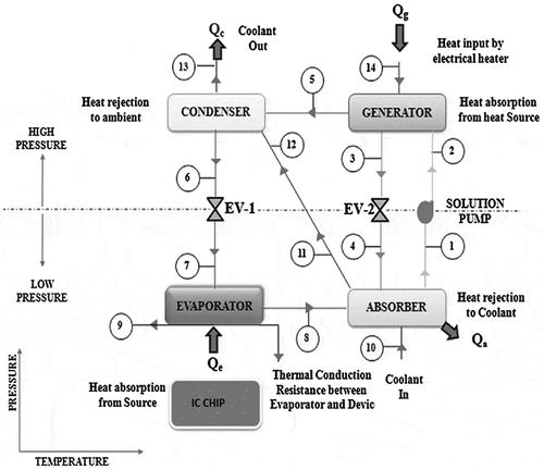
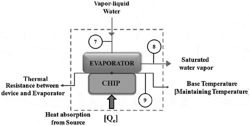
In this study, the evaporator of single-effect LiBr–H2O absorption-based heat pump is etched directly into the back of a chip as shown in Figures and , thereby maintaining the chip temperature at ambient level. The saturated liquid refrigerant (water) coming from the expansion valve (State 7) is vaporised by absorbing the heat dissipated from the chip (State 8). The refrigerant vapour coming from evaporator is exothermically condensed and absorbed into the strong LiBr solution (state point 4), resulting in weak LiBr solution at state point 1. The rejected heat is absorbed by the coolant water as shown in . LiBr solution is pressurised by the liquid pump (State 2). In the generator, the high pressure and high temperature superheated refrigerant water vapour is produced and desorbed from the weak LiBr solution and returns to the refrigerant loop. The superheated water vapour condensed in the condenser and the rejected latent heat is absorbed by the coolant water as shown in .
Assumptions
Pipe pressure drops are negligible.
The heat gain to the evaporator from the surroundings and the heat losses from the generator to the surroundings are negligible.
In the expansion process, the enthalpy is constant.
The water leaving the generator is superheated vapour, water coming out of the condenser is saturated liquid, and water coming out of the evaporator is saturated vapour.
The pressure in the generator is same as the condenser (saturation pressure) and pressure in the evaporator is same as the absorber (saturation pressure).
The temperature difference in the evaporator, condenser, absorbent and generator are negligible.
The coolant outlet temperature from the absorber is the average temperature of inlet and outlet temperature of the coolant from the system.
Temperature of the vapour refrigerant coming out of the generator is the average temperature of inlet and outlet temperature of the solution entering and leaving the generator.
Temperature of the vapour refrigerant leaving the generator is the average temperature of the weak and strong solution saturated temperature in the generator.
2.1. Evaporator analysis
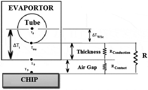
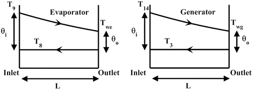
illustrates the evaporator of single-effect LiBr–H2O absorption based heat pump which is etched directly back side of the chip. The refrigerant reaches the evaporator in saturated liquid form and leaves as saturated vapour as shown in the by absorbing the heat which is dissipated from the chip. The size of the evaporator used in chip cooling applications is relatively small and the extensive literatures are available on the design of an evaporator. Number of researchers like Ribeiro et al. (Citation2010), Qi et al. (Citation2009), Mudawar and Weilin (Citation2005), Mudawar (Citation2011), Coggins et al. (Citation2006), França et al. Citation(2014, 2002) and Cunha et al. (Citation2007), Sinha et al. (Citation2015), Rehmana et al. Citation2015) have shown the potential of small parallel channels or microchannels for the desired cooling capacity for chip cooling. Complete thermal conductance model has been formulated for the evaporator with the axis symmetry. The total thermal resistance of the evaporator are R contact and R conduction without considering convective resistance as shown in . The goal of the simulation is to find the influence of chip temperature on COP, load, mass flow rate and conductance of the heat exchangers. The input data are: chip temperature (T 9), total resistance (R), inlet cooling water temperature (T 10), approaching temperature of evaporator or difference in temperature from chip to evaporator (∆T 1), approaching temperature of absorber (∆T 2), approaching temperature of condenser (∆T 3), approaching temperature of generator (∆T 4), evaporator wall superheat (ΔT WSe), generator wall superheat (ΔT WSg) and concentration difference (∆X). A typical loop of calculations might start from point 8 whose temperature is calculated from the input data. Assuming steam leaving the evaporator is dry saturated, the pressure in evaporator is same as the absorber.
Evaporator load is given by:
The typical calculation as follows:
where is the evaporator wall superheat as shown in . The evaporator wall superheat is assumed to be less than the approaching temperature of evaporator.
Wall or surface temperature of the evaporator is given by
In many circumstances, two-dimensional or three-dimensional conduction are facing difficulties in solving the heat diffusion equation. The solutions are reported in terms of a shape factor (S) by Incopera and Bergman (Citation2007), the heat transfer rate may be expressed as
where is the temperature difference between the chip and the wall as shown in and two-dimensional conduction resistance may be expressed as:
Then q e becomes
But, it is significant to identify that in chip cooling, the temperature fall across the interface among sink may be appreciable. This temperature modification is known as the thermal contact resistance . Total resistance (R) becomes,
The mass flow rate of refrigerant from the evaporator is evaluated from the input data
In order to determine the conditions at point 7, the absorber and generator are analysed. But T 11 is not known and it is guessed. The temperature at point 1 can be calculated by:
Concentration of the solution leaving the absorber is given by:
The enthalpy of the solution leaving the absorber and pump remains the same and is given by:
Coolant water leaving the condenser is given by:
The condensing temperature of the refrigerant is given by:
The condensing pressure of the refrigerant is given by:
The enthalpy of the superheated vapour refrigerant leaving the generator is given by:
Concentration of the solution leaving the generator is given by:
Solution temperature leaving the generator is given by:
Enthalpy of the solution leaving the generator is given by:
The heater temperature of the generator is given by:
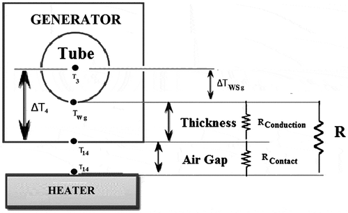
Approaching temperature in the generator is given by:
where is the generator wall superheat as shown in .
Temperature of the vapour refrigerant leaving the generator is given by:
Circulation ratio (CR) is given by:
Mass flow rate of weak solution leaving the absorber is given by:
Mass flow rate of strong solution leaving the generator is given by:
Temperature of the strong solution entering the generator is given by:
The heat balance on the absorber is given by:
The heat balance on the condenser is given by:
Total heat rejected from the system is given by:
Coolant mass flow rate is given by:
The temperature of cooling water at absorber outlet is then,
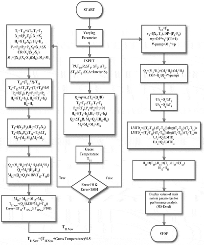
This temperature is now compared with the value predicted in Equation (15). The simulations are repeated until the final value is near to the initial value as shown in . The heat balance on the generator is given by,
Wall or surface temperature of the generator is given by:
Once the calculation of thermodynamic properties at all the state points of the cycle is performed, design specifications can be found easily. The thermal load, logarithmic mean temperature difference and conductance for the evaporator, condenser, absorber, and generator are determined according to the following formulation. Each unit is considered as a counter flow heat exchanger; because of this, logarithmic mean temperature difference is used.
Typical Logarithmic mean temperature difference of evaporator is as shown in and is given by:
Conductance for the evaporator is given by:
Typical Logarithmic mean temperature difference of generator is as shown in and is given by:
Conductance for the generator is given by:
Logarithmic mean temperature difference of condenser is given by:
Conductance for the absorber is given by:
Logarithmic mean temperature difference of absorber is given by:
Conductance for the absorber is given by:
Pump work is given by:
COP is given by:
The simulation begins from a state point in the cycle and continues to the next point. In order to investigate the complete cycle, it is essential to carry out fixed point iteration for T 11. The final values for these properties are examined based on physical reasoning and compared with the initial guessed values. If the final value is not same as the initial value, the simulations are repeated as shown in .
3. Software program
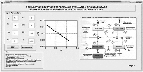
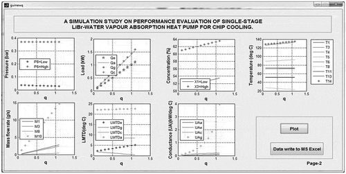
The simulation executes the single-effect LiBr–H2O-based absorption-based heat pump for chip cooling estimated based on the polynomial expressions developed to connect experimental vapour–liquid equilibrium and specific enthalpy–concentration data for LiBr–H2O solutions. This is the renowned superiority of this program as compared with other simulations which experience from lack of exact thermo-physical data. The thermo-physical properties of water have been developed in MATLab (2008b) lab by Magnus Holmgren (2007). Cantarutti (Citation2011) has developed MAT lab code for the properties of LiBr–H2O solution. These functions have been used to develop the software package. The developed GUI contains screens as follows: the Input Page where the chip temperature, approaching temperatures, concentration difference, and total resistance are entered and variation of COP with chip temperature can be observed in the same page. The Output Page-1 shows the variation of thermal load, pressure, temperature, mass flow rates, LMTD and conductance with chip temperature. As an example, the Input Page is shown in and Output page is shown in . The flow chart of the software program is presented in .
4. Validation of the model
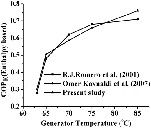
The present model is validated by comparing the results which are present in the literature. The comparative study of COPE (Enthalpy-based Coefficient of Performance) variation of the generator temperature is as shown in . In this simulation, the following data has been used: T e = 2 °C, T c = T a = 30 °C and effectiveness of the solution heat exchanger is kept zero. It can be seen that, as expected, the COPE value raises with rise in generator temperature, and the results found from the current simulation model are in better agreement with the results of Romero et al. (Citation2000) and Kaynakli and Kilic (Citation2007). The small variation can be attributed to the difference among the data-sets utilised for the thermodynamic properties.
The model is further verified and validated by using the reference data from the available literature in which the generator temperature is nearer to that of the waste heat temperature in liquid-cooled or two phase cooled data centres (Tan and Tso Citation2004). shows the values of input data from two references used for the model verification (Tan and Tso Citation2004; Incopera and Bergman Citation2007). Tables and show the validation results. indicates the deviation among present model results and those of Rubio-Maya et al. (Citation2012) result is less than 10%. The deviations are due the model’s differences in computing refrigerant properties as well as density and particular heat of the solution. The comparison indicates good agreement among present model and that of Rubio-Maya et al. (Citation2012) model. In the second verification indicated in , the deviation between present model results and those of Ebrahimi et al. (Citation2015) is less than 10% for the entire load but, there is a greater reduction in the absorber load up to 10%. The comparison shows good agreement between present model and that of Ebrahimi et al. (Citation2015) model.
Table 1. Input data from the simulation of Ebrahimi et al. (Citation2015) and Rubio-Maya et al. (Citation2012).
Table 2. Verification of present model by comparing simulation results of Rubio-Maya et al. (Citation2012).
Table 3. Verification of present model by comparing simulation results of Ebrahimi et al. (Citation2015).
The verification of the model is continued using the reference data from the open literature in which the AHP has series of coolant flow. shows the values of input data from the references used for the model verification (Joudi and Lafta Citation2001). shows a comparison among present model and reference models with respect to all the state points. It is observed from the that the deviation among present model results and those of Joudi and Lafta (Citation2001) is less than 5% with respect to temperature, mass flow rate and concentration, but there is greater reduction of coolant flow rate up to 16%. As observed from , the deviation among present model results and those of Joudi and Lafta (Citation2001) is less than 5% for the entire load, but there is a greater reduction of the absorber load up to 10%. The comparison result shows good agreement between present model and that of Joudi and Lafta (Citation2001) model. The input and output data of the simulation are shown in Tables –.
Table 4. Input data from the simulation of Joudi and Lafta (Citation2001).
Table 5. Verification of model by comparing simulation results of Joudi and Lafta (Citation2001).
Table 6. Verification of model by comparing simulation results of Joudi and Lafta (Citation2001).
Table 7. List of Input parameters for varying chip temperature.
Table 8. Thermodynamic properties (SI units) of state points corresponding to input data in .
Table 9. Design specifications (SI units) corresponding to input data in .
Table 10. Heat pump performance (SI units) corresponding to input data in .
5. Simulation results and discussion
This paper presents the results of simulation program to study the performance and design characteristics of single effect LiBr–H2O-based absorption refrigeration cycles. A typical (Chip temperature = 30 °C) AHP is studied based on the developed model. A set of input data is listed in . The corresponding output data are shown in Tables –.
5.1. Effect of chip heat flux on COP
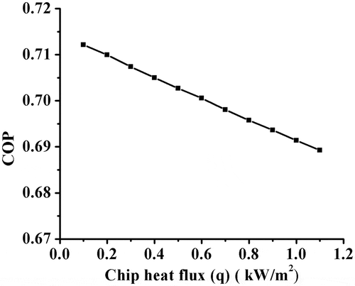
shows the system COP decreases from 0.7121 to 0.68924 as (Chip heat flux) is increased. The values of COP are higher at lower T
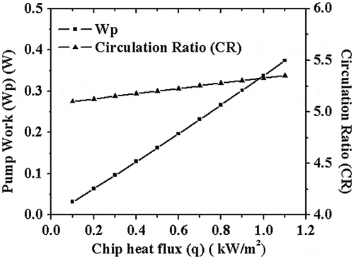
10. This is due to increase in the CR from 5.1015 to 5.352 as shown in and decrease in T
8 i.e. evaporator temperature from 27.6 to 23.6 °C. Keçeciler et al. (Citation2000) have shown that the COP decreases as CR increases. Saravanan and Maiya (Citation1998) and Srinivasa Murthy et al. (Citation2001) have shown that the COP decreases as evaporator temperature decreases. Also, Martínez and Rivera (Citation2009) have verified that with decrease in evaporator temperature, there is a decrease of COP. The results of of the present model are in good agreement with results of Refs. (Kaynakli and Kilic Citation2007; Romero et al. Citation2000; Rubio-Maya et al. Citation2012).
5.2. Effect of chip heat flux on thermal load
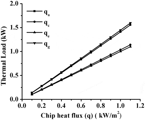
indicates the variations of the thermal load as a function of at a constant approaching temperatures and constant in inlet cooling water temperature of 28 °C. It can be observed from this figure that when
increases, there is a increase in generator load (
) from 0.1403 to 1.595 kW, absorber load (
) from 0.137 to 1.555 kW, condenser load (
) from 0.103 to 1.139 kW and pump work
from 0.0316 to 0.374 W which can be observed from and this is due to increase in CR.Kaushika and Arora (Citation2009), Saravanan and Sekar (Citation2011) have shown that, (
), (
), (
) and (
) loads increase as CR increases. Guo et al. (Citation2012) have verified that, (
), (
), (
) and (
) loads increase as CR increases. Similarly, there is an increase in evaporator load (
) from 0.1 to 1.1 kW, and this is attributed to increase in heat flux. The results of Figures and are valid with the Refs. (Keçeciler et al. Citation2000; Rubio-Maya et al. Citation2012; Saravanan and Maiya Citation1998).
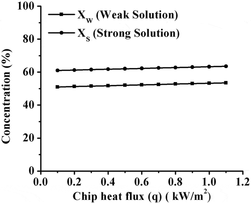
5.3. Effect of chip heat flux on concentration
shows the variations of the concentration as a function of at a constant approaching temperatures and constant in inlet cooling water temperature of 28 °C. There is a minute effect of
on the concentrations and the weak solution coming from the absorber (X
1) increases from 51.01 to 53.52%, and this is because of decrease in evaporator pressure (P
8). Koehler et al. (Citation1988) and Sun (Citation1997) have shown that decrease in solution pressure (evaporator pressure) raises the concentration of the weak solution coming from the absorber. Similarly, there is a rise in concentration of strong solution coming from the generator (X
3) from 61.01 to 63.52%, and this is due to constant in concentration difference (∆X = X
3 − X
1 = 0.1%). The results of are in good agreement with the Refs. (Martínez and Rivera Citation2009; Srinivasa Murthy et al. Citation2001).
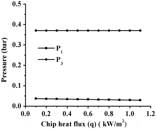
5.4. Effect of chip heat flux on system temperature and pressure
shows the variations of the pressure as a function of at a constant approaching temperatures and constant inlet cooling water temperature of 28 °C. As of
increases, there is a decrease in P
8 from 0.0378 to 0.0291 bar, and this is due to decrease in T
8 from 27.6 to 23.6 °C. Flores et al. (Citation2014) have shown that as the evaporator temperature decreases there is a decrease in evaporator pressure, but there is no effect on condenser pressure (P
3) and it remains constant as 0.3700 bar. The results of are in good agreement with the Refs. (Flores et al. Citation2014).
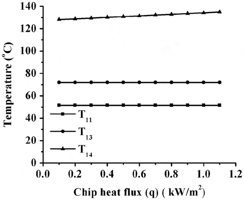
indicates the difference of temperature as a function of at a constant approaching temperature and constant inlet cooling water temperature of 28 °C. As
increases, there is an increase in heater temperature (T
14) from 128.192 to 134.92 °C, and this is due to rise in concentration of the solution leaving the generator resulting in increase in solution temperature of the strong solution coming from the generator (generator temperature (T
3)) from 126.192 to 132.929 °C. Pátek and Klomfar (Citation2006) have shown that generator temperature is a function of solution concentration. Similarly, there is a constant in coolant outlet temperature from the absorber (T
11) as 51.5 °C, and this is due to rise in concentration of the solution leaving the absorber at constant absorber temperature (T
1) of 52 °C and constant in ∆T
2, but coolant outlet temperature from the condenser (T
13) remains constant at 72 °C this is due to condenser temperature (T
6) and ∆T
3 being constant. The results of Figures and are in line with the Refs. (Pátek and Klomfar Citation2006).
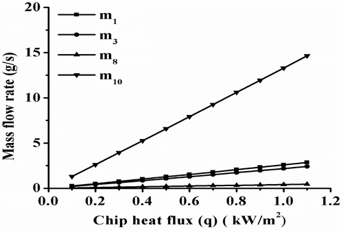
5.5. Effect of chip heat flux on mass flow rate
indicates the difference of mass flow rate as a function of at a constant approaching temperature and constant inlet cooling water temperature at 28 °C. As
increases, there is an increase in the mass flow rate of weak solution coming from the absorber (m
1) from 0.00250 to 0.0028 kg/s and increase in the mass flow rate of strong solution coming from the generator (m
3) from 0.209 to 2.408 g/s, and this is due to increase in CR. Kaushika and Arora (Citation2009) have shown that rise in the concentration of weak solution increases the circulation of m
1 and this results in increase in CR but there is an increase in mass flow rate of refrigerant (m
8) from 0.041 to 0.44 g/s. This is because of increase in the evaporator load and increase in mass flow rate of coolant (water) (m
10) from 0.001307 to 0.01465 kg/s, resulting in the increase in (
) and (
). The results of are good agreement with the Refs. (Kaushika and Arora Citation2009).
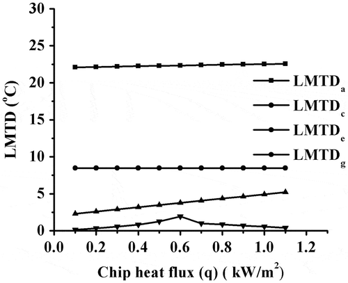
5.6. Effect of chip heat flux on LMTD and conductance
indicates the difference of LMTD as a function of at a constant approaching temperature and constant inlet cooling water temperature of 28 °C. There is a slight increase in trend of LMTDa from 22.104 to 22.55 °C because of slight increase in temperature of the strong solution coming into the absorber (T
4) (71.811–72.667 °C). This results in increase of strong solution concentration coming from the generator. also shows that LMTDc remains constant at 8.46 °C and this is due to stability of outlet temperature in the absorber coolant (T
11). The LMTDg increases from 0.151 to 0.404 °C and LMTDe increases from 2.29 to 5.22 °C. This is due to increase in generator and evaporator load.
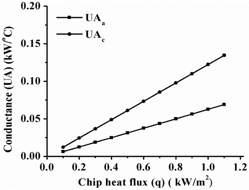
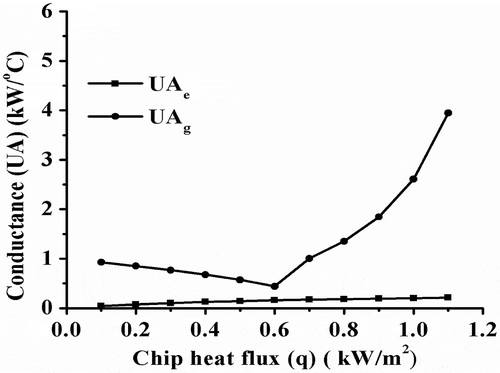
shows the variation conductance as a function of at a constant approaching temperature and constant inlet cooling water temperature at 28 °C. As
increases, there is an increase of UAa from 0.00619 to 0.06897 kW/°C and UAc from 0.0122 to0.1345 kW/°C. This is due to increase in (
) and (
). also shows that there is an increase in UAg from 0.928 to 3.945 kW/°C and UAe increase from 0.043 to 0.21 kW/°C, and this is due to increase in the (
) and (
).
6. Conclusion
In this study, thermodynamic analysis of the single-stage LiBr–H2O vapour AHP for chip cooling in the absence of solution heat exchanger is performed and moreover, a user-friendly visual software package is developed in scope of this study. The model is validated by using the values available in the literature and indicates greater reduction in the absorber load. The simulation results show that the COP value decreases from 0.7121 to 0.68924 with increase in chip heat flux. Further, the CR value of the system shows its significance in deciding the performance and design of the system. The developed user-friendly GUI for LiBr–H2O vapour AHP for chip cooling is advantageous in determining the effect of chip temperature on performance, loads, flow rates and conductance at a faster rate with high accuracy.
| Nomenclature | ||
| CR | = | Circulation ratio |
| E | = | Energy (kJ/s) |
| h | = | Enthalpy (kJ/kg) |
| K | = | Thermal conductivity (W/mk) |
| LiBr–H2O | = | Lithium Bromide–Water |
| LMTD | = | Logarithmic mean temperature difference (°C) |
| = | Mass flow rate (kg/s) | |
| P | = | Pressure (bar) |
| = | Rate of Heat transfer (kW) | |
| R | = | Thermal Resistance (°C/W) |
| S | = | Shape factor |
| T | = | Temperature (°C) |
| UA | = | Conductance (kW/°C) |
| V | = | Specific volume (m3/kg) |
| = | Pump power (kW) | |
| X | = | Concentration (%) |
| Subscript | ||
| a | = | Absorber |
| c | = | Condenser |
| e | = | Evaporator |
| g | = | generator |
| i | = | inlet |
| o | = | outlet |
| w | = | wall |
| ws | = | wall superheat |
| ∆ | = | Difference |
| F | = | flux |
Disclosure statement
No potential conflict of interest was reported by the authors.
Notes on contributors
S. Manu is an assistant professor in the Dept of Mechanical engineering, Sri Siddhartha Institute of Technology, Tumkur. The author’s research interests are Energy, Heat transfer, Refrigeration and air conditioning.
T. K. Chandrashekar is a professor in the Dept of Mechanical engineering, Mangalore Institute of Technology and Engineering, Moodabidri. The author’s research interests are Energy, Heat transfer, IC Engines, Refrigeration and air conditioning.
References
- Agrawal, Tanmay, Varun, Anoop Kumar. 2015. Solar Absorption Refrigeration System for Air-conditioning of a Classroom Building in Northern India. Journal of the Institution of Engineers (India): Series C 96: 389–396. doi:10.1007/s40032-015-0180-2.
- Agyenim, F., I. Knight, and M. Rhodes. 2010. “Design and Experimental Testing of the Performance of an Outdoor LiBr/H2O Solar Thermal Absorption Cooling System with a Cold Store.” Solar Energy 84: 735–744.10.1016/j.solener.2010.01.013
- Alva, L., and J. Gonzalez. 2002. “Simulation of an Air-cooled Solar-assisted Absorption Air Conditioning System.” Journal of Solar Energy Engineering 124 (3): 276–282. doi:10.1115/1.1487885.
- Aphornratana, S., and T. Sriveerakul. 2007. “Experimental Studies of a Single-effect Absorption Refrigerator Using Aqueous Lithium-Bromide: Effect of Operating Condition to System Performance.” Experimental Thermal and Fluid Science 32: 658–669. doi:10.1016/j.expthermflusci.2007.08.003.
- Asdrubali, F., and S. Grignaffini. 2005. “Experimental Evaluation of the Performances of a H2O–LiBr Absorption Refrigerator under Different Service Conditions.” International Journal of Refrigeration 28: 489–497. doi:10.1016/j.ijrefrig.2004.11.006.
- Atilgan, Ibrahim, and Cevdet Aygun. 2014. “Simulation of Double Effect Absorption Refrigeration System.” Progress in Sustainable Energy Technologies 2: 685–703. doi:10.1007/978-3-319-07977-6_45.
- Atmaca, A., and A. Yigit. 2003. “Simulation of Solar-Powered Absorption Cooling System.” Renewable Energy 28: 1277–1293. doi:10.1016/S0960-1481(02)00252-5.
- Bin, Lu, W. J. Meng, and Fanghua Mei. 2012. “Microelectronic Chip Cooling: An Experimental Assessment of a Liquid-Passing Heat Sink, a Microchannel Heat Rejection Module, and a Microchannel-based Recirculating-Liquid Cooling System.” Microsystem Technologies 18 (2): 341–352. doi:10.1007/s00542-011-1397-5.
- Bintoro, J. S., A. Akbarzadeh, and M. Mochizuki. 2005. “A Closed-loop Electronics Cooling by Implementing Single Phase Impinging Jet and Mini Channels Heat Exchanger.” Applied Thermal Engineering 25: 2740–2753. doi:10.1016/j.applthermaleng.2005.01.018.
- Brown, R., E. Masanet, B. Nordman, B. Tschudi, A. Shehabi, J. Stanley, et al. 2008. Report to Congress on Server and Data Center Energy Efficiency: Public Law 109-431. Berkeley, CA: Lawrence Berkeley National Laboratory.
- Brunschwiler, T., B. Smith, E. Ruetsche, and B. Michel. 2009. “Toward Zero-Emission Data Centers through Direct Reuse of Thermal Energy.” IBM Journal of Research and Development 53 (3):1–13.
- Cantarutti, Bruno Ribeiro. 2011. “Theoretical-Experimental Analysis of a Cooling System for Absorption Effect Using Simple LiBr–H2O.” Master thesis. Federal University of Itajuba Institute of Mechanical Engineering Graduate Program in Mechanical Engineering. http://saturno.unifei.edu.br/bim/0038210.pdf.
- Chevron. 2014. Energy Supply and Demand. http://www.chevron.com/globalissues/energysupplydemand/.
- Chiriac, Victor, and Florea Chiriac. 2010. Absorption Refrigeration Method with Alternative Water-Ammonia Solution Circulation System for Microelectronics Cooling. Proceedings of ITHERM 2010, June 2–5, Las Vegas, NY. doi:10.1109/ITHERM.2010.5501391.
- Coggins, C., D. Gerlach, Y. Joshi, A. Fedorov. 2006. “Compact, Low Temperature Refrigeration of Microprocessors.” In: International Refrigeration and Air Conditioning Conference at Purdue, Paper No. R064, West Lafayette, IN, July 15–20. http://docs.lib.purdue.edu/iracc/814/.
- Cunha, Francisco Ricardo, H. L. G. Couto, and N. B. Marcelino. 2007. “A Study on Magnetic Convection in a Narrow Rectangular Cavity.” Magnetohydrodynamics 43 (8): 421–428 http://adsabs.harvard.edu/abs/2007MHD..43.421C.
- Ebrahimi, Khosrow, Gerard F. Jones, and Amy S. Fleischer. 2015. “Thermo-economic Analysis of Steady State Waste Heat Recovery in Data Centers Using Absorption Refrigeration.” Applied Energy 139 (1): 384–397. doi:10.1016/j.apenergy.2014.10.067.
- El-Gohary, Morsy M. 2013. “Economical Analysis of Combined Fuel Cell Generators and Absorption Chillers.” Alexandria Engineering Journal 52 (2): 151–158. doi:10.1016/j.aej.2012.12.004.
- Fan, X., G. Zeng, C. LaBounty, J. E. Bowers, E. Croke, C. C. Ahn, S. Huxtable, A. Majumdar, and A. Shakouri. 2001. “SiGeC/Si Superlattice Microcoolers.” Applied Physics Letters 78 (11): 1580–1582. doi:10.1063/1.1356455.10.1063/1.1356455
- Fan, Y., L. Luo, and B. Souyri. 2007. “Review of Solar Sorption Refrigeration Technologies: Development and Applications.” Renewable and Sustainable Energy Reviews 11 (8): 1758–1775.10.1016/j.rser.2006.01.007
- Flores, Víctor Hugo Flores, Jesús Cerezo Román, and Gisela Montero Alpírez. 2014. “Performance Analysis of Different Working Fluids for an Absorption Refrigeration Cycle.” American Journal of Environmental Engineering 4 (4A): 1–10. doi:10.5923/s.ajee.201401.01.
- Florides, G. A., S. A. Kalogirou, S. A. Tassou, and L. C. Wrobel. 2003. “Design and Construction of a LiBr-Water Absorption Machine.” Energy Conversion and Management 44: 2483–2508. doi:10.1016/S0196-8904(03)00006-2.
- França, Francis Henrique Ramos, Y. M. O. L. K. I. Zhao, M. Ohadi, and M. R. R. Radermacher. 2002. “Flow Boiling of CO2 with Miscible Oil in Microchannels.” ASHRAE Transactions 108 (1): 135–144 http://www.techstreet.com/products/1719532.
- França, Francis Henrique Ramos, Elizaldo D. dos Santos, Liércio A. Isoldi, and Adriane P. Petry. 2014. “A Numerical Study of Combined Convective and Radiative Heat Transfer in Non-reactive Turbulent Channel Flows with Several Optical Thicknesses: A Comparison between LES and RANS.” Journal of the Brazilian Society of Mechanical Sciences and Engineering 36 (1): 207–219. doi:10.1007/s40430-013-0075-1.
- Grossman, Gershon, and Abdi Zaltash. 2001. “ABSIM-Modular Simulation of Advanced Absorption Systems.” International Journal of Refrigeration 24 (6): 531–543. doi:10.1016/S0140-7007(00)00051-7.
- Guo, Peijun, Jun Sui, Wei Han, Jianjiao Zheng, Hongguang Jin. 2012. “Energy and Exergy Analyses on the Off-Design Performance of an Absorption Heat Transformer.” Applied Thermal Engineering 48: 506–514.10.1016/j.applthermaleng.2012.04.018
- Hewitt, Neil, Francis Agyenim, Philip Eames, and Mervyn Smyth. 2010. “A Review of Materials, Heat Transfer and Phase Change Problem Formulation for Latent Heat Thermal Energy Storage Systems (LHTESS).” Renewable and Sustainable Energy Reviews 14 (2): 615–628. doi:10.1016/j.rser.2009.10.015.
- Incopera, Dewitt, and Lavine Bergman. 2007. Fundamental of Heat and Mass Transfer. 6th ed. Wiley.
- Iranmanesh, A., and M. A. Mehrabian. 2012. “Thermodynamic Modelling of a Double-Effect LiBr–H2O Absorption Refrigeration Cycle.” Heat and Mass Transfer 48 (12): 2113–2123.10.1007/s00231-012-1045-3
- Iyengar, M., and R. Schmidt. 2009. “Analytical Modeling for Thermodynamic Characterization of Data Center Cooling Systems.” J Electron Packaging 131: 1–9. EP-08-1048.
- Jiang, L., J. Mikkelsen, J. M. Koo, D. Huber, S. Yao, L. Zhang, P. Zhou, et al. 2002. “Closed-loop Electroosmotic Microchannel Cooling System for VLSI Circuits.” IEEETransactions on Components and Packaging Technologies 25 (3): 347–355. doi:10.1109/TCAPT.2002.800599.
- Joudi, Khalid A., and Ali H. Lafta. 2001. “Simulation of a Simple Absorption Refrigeration System.” Energy Conversion and Management 42: 1575–1605. doi:10.1016/j.solener.2010.01.013.
- Karno, Ali, and Salman Ajib. 2008. “Thermodynamic Analysis of an Absorption Refrigeration Machine with New Working Fluid for Solar Applications.” Heat and Mass Transfer 45 (1): 71–81.10.1007/s00231-008-0408-2
- Kaushika, S. C., and Akhilesh Arora. 2009. “Energy and Exergy Analysis of Single Effect and Series Flow Double Effect Water–Lithium Bromide Absorption Refrigeration Systems.” International Journal of Refrigeration 32 (6): 1247–1258. doi:10.1016/j.ijrefrig.2009.01.017.
- Kaynakli, Omer, and Muhsin Kilic. 2007. “Theoretical Study on the Effect of Operating Conditions on Performance of Absorption Refrigeration System.” Energy Conversion and Management 48: 599–607. doi:10.1016/j.enconman.2006.06.005.
- Keçeciler, Abdullah, H. İbrahim Acar, and Ayla Doğan. 2000. “Thermodynamic Analysis of the Absorption Refrigeration System with Geothermal Energy: An Experimental Study.” Energy Conversion and Management 41 (1): 37–48. doi:10.1016/S0196-8904(99)00091-6.
- Kim, Yoon Jo, Yogendra K. Joshi, and Andrei G. Fedrov. 2008. “An Absorption Based Miniature Heat Pump System for Electronics Cooling.” International Journal of Refrigeration 31: 23–33. doi:10.1016/j.ijrefrig.2007.07.003.
- Koehler, Wolf J., Warren E. Ibele, Joseph Soltes, and Edgar R. Winter. 1988. “Availability Simulation of a Lithium Bromide Absorption Heat Pump.” Heat Recovery Systems and CHP 8 (2): 157–171. doi:10.1016/0890-4332(88)90008-7.
- Lee, S. F., and S. A. Sherif. 2000. “Thermodynamic Analysis of a Lithium Bromide/Water Absorption System for Cooling and Heating Applications.” International Journal of Energy Research 25: 1019–1031. doi:10.1002/er.738.
- Marc, O., F. Lucas, F. Sinama, and E. Monceyron. 2010. “Experimental Investigation of a Solar Cooling Absorption System Operating without Any Backup System under Tropical Climate.” Energy and Buildings 42: 774–782. doi:10.1016/j.expthermflusci.2007.08.003.
- Martinez, P., and J. Pinazo. 2002. “A Method for Design Analysis of Absorption Machines.” International Journal of Refrigeration 25 (5): 634–639. doi:10.1016/S0140-7007(01)00052-4.
- Martínez, H., and W. Rivera. 2009. “Energy and Exergy Analysis of a Double Absorption Heat Transformer Operating with Water/Lithium Bromide.” International Journal of Energy Research 33 (7): 662–674. doi:10.1002/er.1502. http://in.mathworks.com/matlabcentral/fileexchange/9817-x-steam–thermodynamic-properties-of-water-and-steam.
- Maydanik, Y. F., S. V. Vershinin, M. A. Korukov, and J. M. Ochterbeck. 2005. “Miniature Loop Heat Pipes – A Promising Means for Electronics Cooling.” IEEE Transactions on Components and Packaging Technologies 28 (2): 290–296. doi:10.1109/TCAPT.2005.848487.
- Mehrabian, M. A., and A. E. Shahbeik. 2005. “Thermodynamic Modelling of a Single-effect LiBr–H2O Absorption Refrigeration Cycle.” Proceedings of the Institution of Mechanical Engineers, Part E: Journal of Process Mechanical Engineering 219 (3): 261–273. doi:10.1243/095440805X8656.
- Melograno, P., J. Santiago, G. Franchini, and W. Sparber. 2009. Experimental Analysis of a Discontinuous Sorption Chiller Operated in Steady Conditions. 3rd International Conference Solar Air Conditioning Proceedings, Palermo, Italy. http://www.researchgate.net/publication/228607232_Experimental_Analysis_of_a_Discontinuous_Sorption_Chiller_Operated_in_Steady_Conditions.
- Mongia, R., K. Masahiro, E. DiStefano, J. Barry, W. Chen, M. Izenson, F. Possamai, et al. 2006. Small Scale Refrigeration System for Electronics Cooling within a Notebook Computer. In: ITHERM’06, Proceedings of the Tenth Intersociety Conference on Thermal and Thermo mechanical Phenomena in Electronics Systems, San Diego, USA, May 30–June 2: 751–758. doi:10.1109/ITHERM.2006.1645421.
- Mostafavi, M., and B. Agnew. 1996. “The Impact of Ambient Temperature on Lithiumbromide/Water Absorption Machine Performance.” Applied Thermal Engineering 16 (6): 515–522. doi:10.1016/1359-4311(95)00004-6.
- Mudawar, Issam. 2011. “Two-phase Microchannel Heat Sinks: Theory.” Applications, and Limitations, Journal of Electronic Packaging 133: 1–31. doi:10.1115/1.4005300.
- Mudawar, Issam, and Qu Weilin. 2005. “A Systematic Methodology for Optimal Design of Two-phase Micro-channel Heat Sinks.” Journal of Electronic Packaging 127: 381–390. doi:10.1115/1.2056571.
- Nozaki, Y. 2009. “Development of Higher-voltage Direct Current Power Feeding System for ICT Equipment.” NTT Technical Review 7 (10).
- Pal, A., Y. K. Joshi, M. H. Beitelmal, C. D. Patel, and T. M. Wenger. 2002. “Design and Performance Evaluation of a Compact Thermosyphon.” IEEE Transactions on Components and Packaging Technologies 25 (4): 601–607. doi:10.1109/TCAPT.2002.807997.
- Parise, José Alberto dos Reis, J. V. C. Vargas, I. Vargas, T. M. S. Horuz, and J. S. Fleming Callander. 1988. “Simulation of the Transient Response of Heat Driven Refrigerators with Continuous Temperature Control: Simulation de la réponse transitoire des réfrigérateurs utilisant une source de chaleur avec maı̂trise de la température en continu.” International Journal of Refrigeration 21 (8): 648–660. doi:10.1016/S0140-7007(98)00009-7.
- Pátek, J., and J. Klomfar. 2006. “A Computationally Effective Formulation of the Thermodynamic Properties of LiBr–H2O Solutions from 273 to 500 K over Full Composition Range.” International Journal of Refrigeration 29 (4): 566–578. doi:10.1016/j.ijrefrig.2005.10.007.
- Pongtornkulpanich, A., S. Thepa, M. Amornkitbamrun, and C. Butcher. 2008. “Experience with Fully Operational Solar-Driven 10-Ton LiBr/H2O Single-effect Absorption Cooling System in Thailand.” Renewable Energy 33: 943–949. doi:10.1016/j.renene.2007.09.022.
- Qi, Zhaogang, Jiangping Chen, and Reinhard Radermacher. 2009. “Investigating Performance of New Mini-channel Evaporators.” Applied Thermal Engineering 29 (17–18): 3561–3567. doi:10.1016/j.applthermaleng.2009.06.011.
- Rahimifard, Shahin, Elliot Woolley, Yang Luo, and Alessandro Simeone. 2014. “Improving Energy Efficiency within Manufacturing by Recovering Waste Heat Energy.” Journal of Thermal Engineering 1 (1): 337–344.
- Rehmana, M., S. Noreenb, A. Haiderc, and H. Azamd. 2015. “Effect of Heat Sink/Source on Peristaltic Flow of Jeffrey Fluid through a Symmetric Channel.” Alexandria Engineering Journal. 54 (3), September 2015, 733–743. doi:10.1016/j.aej.2015.03.011.
- Ribeiro, Guilherme B., Jader R. Barbosa, Jr., and Alvaro T. Prata. 2010. “Mini-channel Evaporator/Heat Pipe Assembly for a Chip Cooling Vapor Compression Refrigeration System.” International Journal of Refrigeration 33 (7): 1402–1412. doi:10.1016/j.ijrefrig.2010.05.010.
- Romero, R. J., W. Rivera, and R. Best. 2000. “Comparison of the Theoretical Performance of a Solar Air Conditioning System Operating with Water/Lithium Bromide and an Aqueous Ternary Hydroxide.” Solar Energy Material Solar Cells 63 (3): 87–99. doi:10.1016/S0927-0248(00)00058-1.
- Rubio-Maya, Carlos, J. Jesús Pacheco-Ibarra, Juan M. Belman-Flores, Sergio R. Galván-González, and Crisanto Mendoza-Covarrubias. 2012. “NLP Model of a LiBr–H2O Absorption Refrigeration System for the Minimization of the Annual Operating Cost.” Applied Thermal Engineering 37: 10–18.10.1016/j.applthermaleng.2011.12.035
- Saravanan, R., and M. P. Maiya. 1998. “Thermodynamic Comparison of Water-based Working Fluid Combinations for a Vapor Absorption Refrigeration System.” Applied Thermal Engineering 18 (7): 553–568. doi:10.1016/S1359-4311(97)00072-0.
- Saravanan, R., and S. Sekar. 2011. “Experimental Studies on Absorption Heat Transformer Coupled Distillation System.” Desalination 274: 292–301. doi:10.1016/j.desal.2011.01.064.
- Sedighi, K., M. Farhadi, and M. Liaghi. 2007. “Exergy Analysis: Parametric Study on Lithium Bromide – Water Absorption Refrigeration Systems.” Proceedings of the Institution of Mechanical Engineers, Part C: Journal of Mechanical Engineering Science 221 (11): 1345–1351. doi:10.1243/09544062JMES604.
- Sencana, Arzu, Kemal A. Yakut, and Soteris A. Kalogirou. 2005. “Exergy Analysis of Lithium Bromide/Water Absorption Systems.” Renewable Energy 30: 645–657. doi:10.1016/j.renene.2004.07.006.
- Sinha, A., G. C. Shit, and N. K. Ranjit. 2015. “Peristaltic Transport of MHD Flow and Heat Transfer in an Asymmetric Channel: Effects of Variable Viscosity, Velocity-Slip and Temperature Jump.” Alexandria Engineering Journal. 54 (3), September 2015, 691–704. doi:10.1016/j.aej.2015.03.030.
- Srinivasa Murthy, S., M. B. Arun, and M. P. Maiya. 2001. “Performance Comparison of Double-effect Parallel-Flow and Series Flow Water–Lithium Bromide Absorption Systems.” Applied Thermal Engineering 21 (12): 1273–1279. doi:10.1016/S1359-4311(01)00005-9.
- Sun, Da-Wen. 1997. “Thermodynamic Design Data and Optimum Design Maps for Absorption Refrigeration Systems.” Applied Thermal Engineering 17 (3): 211–221. doi:10.1016/S1359-4311(96)00041-5.
- Talbi, M. M., and B. Agnew. 2000. “Exergy Analysis: An Absorption Refrigerator Using Lithium Bromide and Water as the Working Fluids.” Applied Thermal Engineering 20: 619–630. doi:10.1016/S1359-4311(99)00052-6.
- Tan, F. L., and C. P. Tso. 2004. “Cooling of Mobile Electronic Devices Using Phase Change Materials.” Applied Thermal Engineering 24: 159–169. doi:10.1016/j.applthermaleng.2003.09.005.
- Trutassanawin, Suwat, Eckhard A. Groll, Suresh V. Garimella, and Lorenzo Cremaschi. 2006. “Experimental Investigation of a Miniature-Scale Refrigeration System for Electronics Cooling.” IEEE Transactions on Components and Packaging Technologies 29: 678–687.10.1109/TCAPT.2006.881762
- Tuckerman, D. B., and R. F. W. Pease. 1981. “High-performance Heat Sinking for VLSI.” IEEE Electron Device Letters 2: 126–129. doi:10.1109/EDL.1981.25367.
- Yang, W.-J., and K. H. Guo. 1987. “Solar-assisted Lithium-Bromide Absorption Cooling Systems.” Solar Energy Utilization NATO ASI Series 129: 409–423. doi:10.1007/978-94-009-3631-7_19.
- Yoon, Jung-In, Kwang-Hwan Choi, Choon-Geun Moon, Young Jin Kim, and Oh- Kyung Kwon. 2003. “A Study on the Advanced Performance of an Absorption Heater/Chiller with a Solution Preheater Using Waste Gas.” Applied Thermal Engineering 23: 757–767. doi:10.1016/S1359-4311(03)00003-6.

