Abstract
The objective of this paper is to discuss the main barriers for modelling and integrating the environmental performances in the automotive concept design. Incorporating environmental assessment in the early design phase of a vehicle component is known as an important challenge that car makers need to face in order to develop more sustainable design solutions; in this regard, the Life Cycle Assessment is the most widespread methodology for the environmental assessment and comparison of alternatives. The present work illustrates the combination of such methodology with the traditional design procedure at two different levels of the component design phase, material choice and concept design. In particular, the potential benefits originated by a lightweight solution for the automotive component Throttle Body are evaluated by considering environmental and technical implications at the same level. The case study shows that a multi-disciplinary approach for design effectively allows the integration of the environmental issue in the company’s established procedures. However, interpretation of results is still a challenging aspect due to the inevitable contradicting elements which should not discourage to develop comprehensive sustainability assessment within the early design stage.
Introduction
Car manufacturers have implemented several technical strategies in order to meet legislation requirements and satisfaction of consumer expectations. Examples of these strategies include mass reduction, improvement in aerodynamics, powertrain efficiency and safety, alternative propulsion systems (Jasinski, Meredith, and Kirwan Citation2015). Lightweight design is particularly investigated by OEMs since it allows consistent reductions in terms of fuel demand and air pollutant emissions. One of the most effective strategies for obtaining mass reduction is the re-design of vehicle parts via material substitution. In this context, a key factor is the material selection phase, along with advancements in materials research and related manufacturing technologies. The material selection needs to balance several antithetical aspects (performances, feasibility, recyclability and environmental sustainability) and this leads to necessarily face controversial issues (Andriankaja et al. Citation2015; De Medina Citation2006; Kelly et al. Citation2015; Raugei et al. Citation2015). In particular, innovative lightweight materials (such as composites and biopolymers, hybrid materials, high-strength metal alloys) are considered promising substantial improvements in terms of mass reduction but some aspects regarding their environmental consequences still need to be investigated.
Literature provides several methods for identifying the best alternative within a panel of different lightweight design solutions. Considering the Design-for-Environment, the main capabilities offered by an eco-design tool are the critical comparison of alternative product concepts and the identification of improvement options such as alternative materials/processes (Andriankaja et al. Citation2015). Several methods and tools are currently applied by designers such as full Life Cycle Assessment (LCA), LCA-based tools, Matrix-based tools, Guidelines, Checklists, Eco-design guides, Parametric tools and Solution Decision-making tools (Andriankaja et al. Citation2015; Arena, Azzone, and Conte Citation2013; Mayyas et al. Citation2012a). But even so, the need for effective tools able to compare and select appropriate materials during an early design phase is still a research field (Arena, Azzone, and Conte Citation2013; Poulikidou et al. Citation2015). Some authors study the combination of materials selection with structural optimisation, weight minimisation and environmental assessment, with the aim of enhancing a systematic evaluation of material alternatives (Ermolaeva, Castro, and Kandachar Citation2004; Poulikidou et al. Citation2015). In other cases, the focus is the assessment and inclusion of specific indicators (e.g. recyclability) or a set of key sustainability indicators along vehicle life cycle (Arena, Azzone, and Conte Citation2013; Sakundarini et al. Citation2013). In sustainable product design, such tools should be able to elaborate and integrate different information (technical, environmental and economic) and provide a score system able to support material selection according to a multi-criteria approach (Dattilo et al. Citation2017; Sakundarini et al. Citation2013). In response to a more comprehensive assessment, the wide variety of parameters is responsible for a higher complexity of the analysis and the necessity of a multi-disciplinary working group (e.g. designer, material specialist, environmental analyst) (Poulikidou et al. Citation2015; Sakundarini et al. Citation2013).
In many cases, the LCA methodology is used for the environmental assessment of materials during the concept design phase (Arena, Azzone, and Conte Citation2013; Ermolaeva, Castro, and Kandachar Citation2004; Maltese et al. Citation2017; Poulikidou et al. Citation2015; Simões et al. Citation2016; Witik et al. Citation2011). Overall, the LCA is widely applied within the automotive field, as demonstrated by the numerous Environmental Product Declarations of cars (Mercedes-Benz Citation2013; Renault Citation2011; Volkswagen AG Citation2012) and publications exploring the potential of lightweighting to lower transport environmental impact. Some studies deal with the system-level analysis (e.g. Body-in-White) (Duflou et al. Citation2009; Mayyas et al. Citation2012b; Raugei et al. Citation2015; Schuh, Korthals, and Backs Citation2013) while other ones take into account specific vehicle parts (e.g. engine block, passenger seat) (Alves et al. Citation2010; Andriankaja, Bertoluci, and Millet Citation2009; Das Citation2011; Delogu et al. Citation2016; Dhingra and Das Citation2014; Kelly et al. Citation2015; Park et al. Citation2013; Subic et al. Citation2010; Tharumarajah and Koltun Citation2007, 2010). The substitution of traditional metals with composites is one of the most studied issues (i.e. Das Citation2011; Kelly et al. Citation2015; Mayyas et al. Citation2012b; Park et al. Citation2013; Schuh, Korthals, and Backs Citation2013), whereas few researches compare alternative composites (Alves et al. Citation2010; Delogu et al. Citation2015; Luz, Caldeira-Pires, and Ferrão Citation2010; Rajendran et al. Citation2012). Nevertheless, despite the high number of studies on this topic, a clear and homogeneous overview is still missing. Environmental assessment is mainly focused on Green-House Gas (GHG) emissions and life-cycle energy demand (Das Citation2011; Dhingra and Das Citation2014; Kelly et al. Citation2015; Mayyas et al. Citation2012b; Schuh, Korthals, and Backs Citation2013; Tharumarajah and Koltun Citation2010; Witik et al. Citation2011) while only a minor part attempts to assess and discuss a larger set of environmental impact categories (Andriankaja, Bertoluci, and Millet Citation2009; Delogu et al. Citation2016; Raugei et al. Citation2015; Subic et al. Citation2010). However, other impacts, such as resource depletion and toxicity among others, need to be assessed (Delogu et al. Citation2016; Raugei et al. Citation2015). Indeed, all these works suggest that a unique answer does not exist as many aspects influence the final results (Kim and Wallington Citation2013; Raugei et al. Citation2015) and trade-off. The delicate balance between the opposite effects involved by lightweighting (use stage impact reduction and increase in production stage impact) is generally encountered and discussed (Andriankaja et al. Citation2015; Kelly et al. Citation2015; Mayyas et al. Citation2012b; Raugei et al. Citation2015). In addition, a trade-off among different categories could be found (Delogu et al. Citation2016). Consequently, the capability of managing trade-off in a transparent and comprehensive way is a fundamental feature that a decision-support tool should provide.
Besides the high number of studies, the implementation and integration of LCA principles within the overall design process are still characterised by some challenges. The first issue is related to the possibility of introducing the LCA methodology within the existing design process; the second issue concerns the necessity to identify all the environmental criticalities related to lightweighting, according to literature findings (Arena, Azzone, and Conte Citation2013; Simões et al. Citation2016) and reliable trade-off. Generally, the environmental assessment is performed within an early design phase only if it is based on a single indicator, or at least few indicators (Bovea and Gallardo Citation2006). Unlike this need, literature suggests the importance of using a set of different indicators in order to estimate the environmental impacts in a comprehensive way and avoid burden shifting (Delogu et al. Citation2016). For this reason, methodological developments in LCA go in the direction of developing impact categories and indicators specific for each industrial sector (Andriankaja, Bertoluci, and Millet Citation2009; Andriankaja et al. Citation2015; Del Duce et al. Citation2013; Renault Citation2011). Consequently, it is fundamental to develop the overall design process through a multidisciplinary approach which envisages the simultaneous involvement of designers, materials specialists, environmental experts as well as procurement or sales representatives (Poulikidou et al. Citation2015).
Although several studies have been carried out on material selection in the product design stage, most of these researches rely on hypothetical case studies, thus not deepening some of the challenges like data exchange and interpretation of results. That said, the contribution of this paper is identifying and discussing the main barriers for the integration of environmental performances within the concept design stage according to a realistic case study. In particular, the research deals with the following specific aspects:
| • | integration of environment within the traditional design procedure; | ||||
| • | exchange of information among expertise and primary data collection; | ||||
| • | analysis and interpretation of the environmental results. | ||||
Method
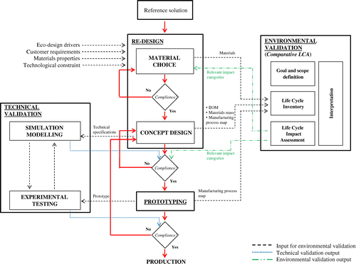
Figure describes the method adopted for the study. The workflow shows that the traditional design procedure is combined with the environmental assessment at two different levels of the component design: material selection and concept design. Unlike traditional design approaches, the environmental implications of the new design solution are considered at the same level of functional and mechanical performance, thus becoming a key element in the decision-making process. In this context, the environmental validation section provides fundamental feedbacks on which both material selection and final design definition are based. The inclusion of the environmental issue between the main drivers of the design approach means that the overall process is based on a supportive collaboration of research and design team, such as designers, test engineers, manufacturers, suppliers and LCA-experts. The workflow is thought in the context of lightweight design and it is composed by four main steps which are carried out in a consecutive way: Re-design, Technical validation, Environmental validation and Prototyping.
The Re-design step deals with material selection and concept design according to specific eco-design drivers (i.e. design for materials), customer requirements, material properties and technological constrains. Material selection is mainly guided by physical properties that guarantee component mechanical performances as well as mass reduction; technological performances guide the material choice and they strongly depend on the specific component, its function and customer requirements. Moreover, in this phase, the environmental performances of several alternative materials are compared to the reference one. Data exchange with environmental expertise is therefore carried out. A first compliance regards material properties and it is preparatory to the following concept design. Once the concept is identified, technical specifications (e.g. materials, geometries) are provided for the simulation modelling; in parallel the designer exchanges concept information (i.e. geometry, bill of materials, masses) with the environmental analyst. The main data that are needed for the environmental validation are the bill of materials (BOM), geometries, masses and the manufacturing process map; moreover, also technical data about the reference vehicle are necessary for an appropriate use stage modelling.
The Technical validation comprises two aspects: simulation modelling of the concept and experimental tests of the prototype. These steps are actually performed in parallel with the concept design and prototyping phases.
The Environmental validation step is performed through a comparative LCA study of reference and innovative solutions for the given component. The LCA methodology, developed according to the ISO standard 14040, compels a four-phase procedure: goal and scope, inventory, impact assessment and interpretation of results. The life cycle inventory is the most critical step since it requires an intensive data collection for the environmental modelling of the whole component life cycle. The main inputs for this phase come from the designer but also from material supplier and manufacturers; however, also additional activities of data gathering and database consultation are required. The impact assessment involves the calculation of several impact indicators which are defined by the specific assessment method (EC-JRC European Commission Citation2011). The selection of the most relevant indicators is necessary in order to enhance the integration of LCA within the early concept design phase; as the LCA outcomes address the most important environmental issues, designers are called to actively participate to results interpretation.
According to Del Duce et al. (Citation2013), the impact categories which should be evaluated for a complete assessment are: Climate Change, (Stratospheric) Ozone depletion, Human toxicity, Respiratory inorganics, Ionizing radiation, (Ground-level) Photochemical ozone formation, Acidification (land and water), Eutrophication (land and water), Ecotoxicity, Land use, Resource depletion (metals, minerals, fossil, nuclear and renewable energy sources, water). However, the selection of indicators is also guided by feasibility and legislation requirements for the specific sector. For this reason some companies have built up a screening process according to which global warming, abiotic depletion and energy demand gain the highest score, followed by water eutrophication, photochemical pollution and acidification (Renault Citation2011). In this study, six categories are selected: Global Warming Potential (GWP 100 years), Eutrophication Potential (EP); Ozone Depletion Potential (ODP); Photochemical Ozone Creation Potential (POCP); Abiotic Depletion Potential elements (ADPelements); Primary Energy Demand (PED).
As previously mentioned, the environmental validation exchanges inputs/outputs at two different levels of the design process. The first one is the material selection step where the LCA is used to compare alternative materials according to different environmental impact categories (cradle-to-gate assessment). The second one is the concept design and it provides impact assessment results concerning the component life cycle (cradle-to-grave assessment). A second decision-making step is then present, where the concept compliance is evaluated according to simulation and environmental validation results. If both validations provide a positive feedback, the concept is accepted for the Prototyping stage. The prototype undergoes experimental testing needed in order to validate functional and mechanical performances. If materials, geometries and manufacturing do not require relevant changes, there are no additional environmental validations and experimental testing is performed in order to endorse the component production.
Case study
The eco-design workflow depicted in Figure is applied to the re-design of the Throttle Body (TB), an engine compartment component developed and produced by MM. The eco-design drivers are reduction of energy consumption and de-materialisation. The aim is double: on one hand improving the environmental profile of the component while maintaining all functional requirements of the reference solution, on the other hand enhancing vehicle performance through mass reduction.
Reference solution
The main functions of TB are setting engine inlet air flow to the cylinders based on pressure exerted by driver on accelerator pedal, while guaranteeing the minimum air flow rate at engine idle speed and providing the minimum air flow rate in case of malfunctioning. TB is interfaced with air inlet filter (at input) and engine intake manifold (at output); the regulation of net air flow is performed through a valve plate. Table reports all parts that compose the reference design solution for TB (aluminium alloy housing TB) as well as an exploded view of the entire assembly. TB is an electromechanical component composed by a main part, the housing, made with aluminium alloy in the reference design solution, and many other small parts characterised by high miniaturisation and different materials. Consequently, TB re-design and the following environmental validation present a high level of complexity.
Table 1. List of TB parts, materials and masses for the current solution (aluminium alloy housing TB) and the new one (PETGF housing TB).
Re-design
The main purpose of TB re-design is mass reduction in order to lower vehicle weight. Although it represents a small component in comparison to other parts, the simultaneous application of lightweighting to several vehicle components represents a strong point of interest. This is demonstrated by the numerous studies regarding different car parts, such as section floor (Das Citation2011), engine (Dhingra and Das Citation2014), passenger seat (Subic et al. Citation2010) and dashboard (Delogu et al. Citation2016), as well as structural sections (EU-project ENLIGHT,Footnote1 ALIVEFootnote2).
Material selection
Material selection regards the housing part as the most important in terms of mass. In the reference design solution, the housing is made of secondary aluminium alloy (EN AC-46100); therefore, alternative materials that could guarantee the design target of mass reduction are selected. In this sense, magnesium alloys and beryllium could represent alternatives but they are discarded because of their high cost and toxicity level. The application of plastic materials in automotive engineering is rapidly increasing (Carlson et al. Citation2013). Up to date about 12–15% of a modern car mass is made of plastic (PlasticsEurope Citation2010) and, currently, extending the use of polymers to engine components is one of the challenges (Defosse Citation2009). The use of plastic materials for engine parts is adopted since, besides the weight saving, they provide many advantages such as noise reduction, rustproof, easy design/assembly processes, economic convenience (Defosse Citation2009; Klein and Wiese Citation2011). Indeed, mechanical, thermal and electrical properties of plastic materials are definitely lower with respect to the ones of metals; in order to achieve the same performance level, plastics often need to be strengthened through to the addition of additives. Some authors deal with the adoption of composites for automotive engine compartment parts, and technical feasibility is evidenced as a major issue. Engine components are cyclically loaded and subjected to temperatures up to 120 °C, humidity, oil, cooling medium; therefore, the applicability of composite mainly depends on the assessment of strength features during service life. Sonsino and Moosbrugger (Citation2008) develop a fatigue design procedure for a short glass fibre-reinforced polyamide PA66-GF35 fuel rail whereas Guster et al. (Citation2011) present the experimental results of fatigue tests conducted on a 50% glass fibre-reinforced polyamide. Overall, temperature as well as fibre orientation are found the parameters that mostly influence fatigue behaviour of the considered polymer. A significant application is represented by 35% glass fibres-reinforced Polypropylene (PP) Air Intake Manifold (AIM) adopted in 2010 by Volkswagen Group®, the first automotive OEM to use PP for such a component. The advantages of using PP reinforced with glass fibres are a long-term high heat and chemical resistance, vibration/fatigue resistance and a larger range of operating temperature. Moreover, this material allows using conventional plastics manufacturing processes and shows better acoustic performance with a lower density in comparison to polyamide. The introduction of plastic as construction material for AIM has been widely investigated in the past also from an environmental point of view (Delogu et al. Citation2016; Keoleian and Kar Citation2003; Spitzley and Keoleian Citation2001; Villalva et al. Citation2012).
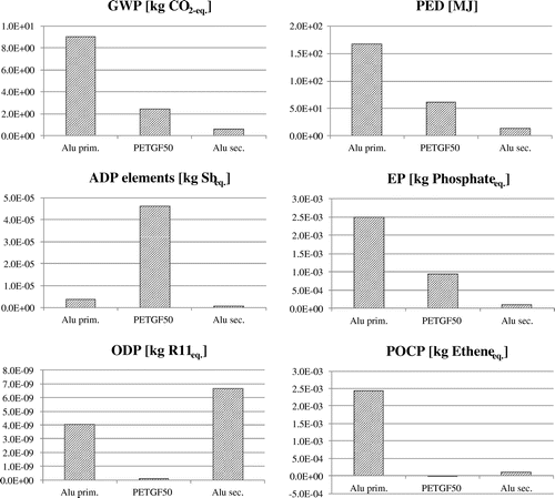
In the present case study material selection is mainly guided by the component function and working conditions such as mechanical and thermal features. According to a lightweight perspective, the density is considered as the first parameter for the selection, followed by hydrolysis resistant properties. Among the various options, the glass fibres-reinforced PET is selected. Although its applicability for the engine components has not been already experienced, PET fulfils the requirements for dimensional stability at the working temperature for the entire lifetime of the component. Moreover, from a technical point of view the value of density, water absorption (0.3%) and humidity absorption (0.12%) are found acceptable. The new material, based on different fibre reinforcement percentage, is also compared to the reference one (per kilogram of material) from the environmental point of view, according to the aforementioned impact categories and GaBi database (Figure ). The eco-profile of the reference aluminium alloy is built according to the real composition provided by the material supplier (aluminium scrap 92%, silicon 7%, primary aluminium 1%); therefore, primary data, supported by the database processes, are used. The results, shown in Figure , refer to a ‘from cradle-to-gate’ assessment; overall they are in favour of the current material with the exception of two impact categories (ODP and POCP). The fibre amount is found to notably influence the impact of composite; the higher GF amount the lower GWP and PED values, whereas higher reinforcement involves an increase of ADPelements and EP.
It is evident that the comparison of alternative materials eco-profiles can provide only partial information (related to materials production); moreover, the employment of new materials is not encouraging. In fact, according to literature findings innovative materials like composites or new metal alloys generally provide relevant benefits in terms of mass reduction at the expense of burdens increase during production stage (Witik et al. Citation2011). Consequently, the PETGF alternative design solution is chosen as it allows fulfilling a notable mass reduction while maintaining technical and functional performances.
Concept design
Figure shows the exploded view of both reference and innovative TB solution while Table lists component parts, materials and masses. The main difference between the reference and the lightweight design solution is the material adopted for the housing part. The substitution of the secondary aluminium alloy with glass fibres-reinforced PET allows 50% mass reduction of this part which represents a 26% weight reduction over the entire TB.
Figure 3. Exploded view of the current TB solution (aluminium alloy housing TB) and the new one (PETGF housing TB).
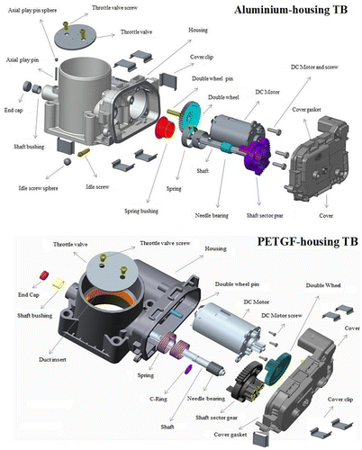
The material substitution is responsible for the change in manufacturing technology: pressure die casting is replaced by injection moulding process. Besides mass reduction due to the lower density of the housing, further modifications are applied in order to achieve additional mass reduction; finally the overall TB mass reduction is 22% (Table ). These minor changes are detailed in the following points:
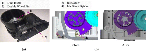
| • | introduction of co-moulded metallic duct insert into the housing (Figure (a)); | ||||
| • | repositioning of spring bushing into the housing without any support; | ||||
| • | elimination of idle screw and idle screw sphere (Figure (b)); | ||||
| • | replacement of axial play pin with a C-Ring located in the shaft groove; | ||||
| • | introduction of a double wheel-pin over-moulded in the housing. | ||||
Environmental validation
The environmental validation is performed by the LCA methodology. Since the methodology relies on the ISO standard 14040, a specific expertise of data exchange with several figures (e.g. designers, material suppliers) is required. The following paragraphs describe the four phases that characterise the comparative LCA of reference and innovative design solutions.
Goal and scope definition
The Functional Unit (FU) is one TB produced and used for a vehicle life distance of 150000 km. The same functionality is provided by both solutions (aluminium housing TB and PETGF-housing TB), thus allowing comparability of environmental performances. The main function is setting engine inlet airflow to the cylinders of a 1400-cc gasoline turbocharged car with a limp-home flow rate of about 25 kg/h and an idle flow rate tolerance less than 2 kg/h.
According to a ‘from cradle-to-grave’ approach, TB life cycle stages are materials supply, production, logistic, use and End-of-Life (EoL); Table reports the processes included for each stage subdivided in foregroundFootnote3 and backgroundFootnote4 unit processes. TB life cycle processes excluded from the study are those regarding small parts (e.g. needle bearing) since they are expected to have negligible influence on the total impact of TB life cycle.
Table 2. Schematisation of TB LC stages and related processes included in the analysis (F = foreground process; B = background process).
Life cycle inventory
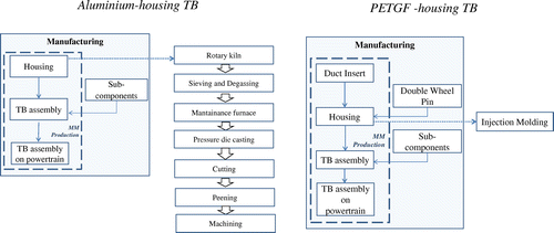
Data collection of materials, energy and waste flows entering/exiting the processes are carried out according to the process type: for the foreground processes, site-specific data are collected (TB manufacturing technologies reported on the map) (Figure ) while for the background processes data-set of GaBi database are used.
Materials typology and quantities are reported in Table ; data-set used for their analysis are listed in the Supplementary Material (Table A and B). Table reports all the input/output flows measured for each manufacturing technologies and TB assembly. The TB assembly is not modelled since it is a manual operation that does not involve additional flows.
Table 3. Input and output flow measured for the housing manufacturing technologies.
For the transportation step, data collection consists of truck type, travelled distances, calculated by means of web map-routing services (Google Maps®), and route composition (highway and urban). The modelling of logistic data is the same for both design solutions. All details are reported in the Supplementary Material (Table C).
The use stage data collection involves the quantification of fuel consumption (FC) and emissions figures which can be ascribed to the TB. At this scope, an analytical model for consumption and emissions is adopted (Ridge Citation1997). The calculation is based on the correlation between the percent quota of car mass represented by the TB and the percent quota of vehicle FC attributable to the TB. Equations and data era reported in Table .
Table 4. Use stage modelling: equations and data.
Dismantling time and component mass are crucial factors in order to determine whether the TB is removed at EoL (Berzi et al. Citation2013; Cossu et al. Citation2014; Delogu et al. Citation2016; Jenseit et al. Citation2003; Krinke et al. Citation2009). The chosen EoL scenario envisage that TB remains on the ELV, thereafter it is led to the shredding and milling processes, contributing to the production of the so-called fluff or Automotive Shredder Residue (ASR). After the shredding, an ASR separation process is assumed. This latter sorts ASR into two different material fractions by using magnetic properties and eddy current separators: the first one, named Shredder Heavy Fraction (SHF), comprising pure ferrous materials and non-ferromagnetic materials; the second one, named Shredder Light Fraction (SLF), is a mix of different materials and substances such as plastics, fibres, glass, elastomers and residue. SHF is assumed recycled, thus leading to environmental credits in terms of resources consumption, while SLF is assumed to be landfilled. All the processes involved are assessed according to the related data-set available in the GaBi database.
Life Cycle Impact Assessment and interpretation of results
Table reports the Life Cycle Impact Assessment (LCIA) results for Aluminium alloy housing TB and PETGF-housing TB; results are expressed both per total life cycle and per single stage.
Table 5. LCIA results for aluminium housing TB and PETGF-housing TB.
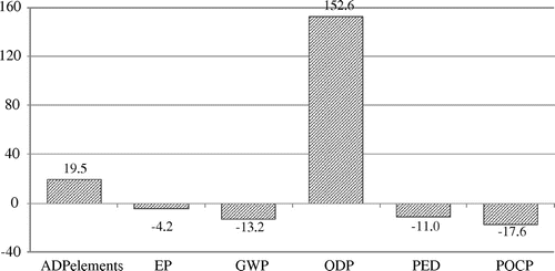
The comparison between reference solution and innovative one (Figure ) shows that the lightweight TB involves a considerable reduction of impacts for the major part of categories. ADPelements and ODP, for which PETGF-housing TB presents higher impacts with respect to the aluminium one, represent the only exceptions, especially for ODP whose increase exceeds 150%; this is due to resources consumption and air emissions involved by raw materials extraction and production processes.
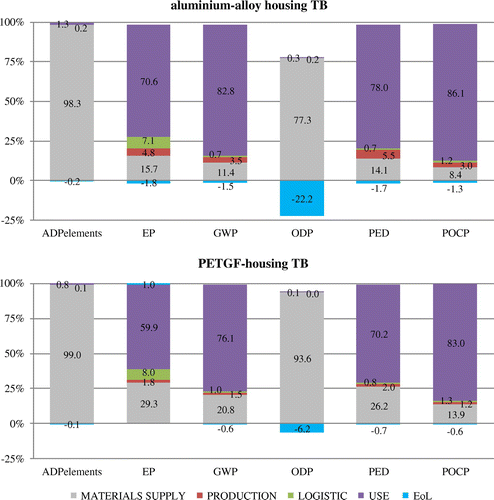
The contribution analysis by life cycle stage of impact is reported in Figure . Overall, the most influential stages are materials supply and use. Such an outcome is due to the energy and resources consumption involved by raw materials extraction and production processes, while the considerable amount of FC and emissions during operation are the only factors that influence the use stage impact. Manufacturing, logistic and EoL stages present minimal contributions to all impact categories with the exception of ODP for witch EoL involves a not negligible reduction of the overall impact. The replacement of aluminium alloy with glass fibre-reinforced plastic leads to a reduction of manufacturing, use and EoL quota for all impact categories. The PETGF-housing manufacturing requires lower energy consumption if compared to the aluminium one. The reduction of EoL impact is a consequence of the different material composition of the housing; indeed, metals are generally characterised by a sorting and recycling efficiency close to 100%, thus allowing higher potential impacts credits in comparison to the composite solution.
Figure 7. Contribution analysis by LC stage of impacts for aluminium alloy housing TB and PETGF-housing TB.
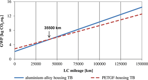
The use stage represents a considerable quota of total LC environmental load, therefore, a break-even analysis, based on vehicle mileage, is performed taking into account the GWP value (Figure ). At zero kilometres the GWP of the PETGF-housing TB presents higher impacts with respect to the aluminium housing TB. On the other hand, the slope of the line that represents the use stage impact is lower for the innovative solution with respect to the reference one. The break-even mileage for the effective environmental convenience is around 35000 km, while at 150000 km PETGF-housing TB guarantees a 13% impact reduction in terms of GWP. As a consequence, the innovative solution is found preferable since it results environmentally convenient from an early vehicle life span.
Prototyping and technical validation
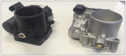
Technical validation includes simulation modelling of the concept and the experimental tests of the prototype. Simulation modelling mainly relies on FEM modelling; however, as providing details about this step is out of the scope of this paper, only some information regarding the experimental tests are included. Tests are performed on the prototype in order to verify both feasibility and functional/performance requirements of the component. Types and sequence of tests depend on both component features and customer requirements. In this case, the TB is designed for a minimum service life of 15 years (7000 operating hours or 300000 km mileage) and its technical validation is carried out according to five consequential steps. Prototypes of both housing solutions are produced are reported in Figure .
The first test is the functional characterisation of the new design and it aims at verifying airflow measurement at lower mechanical stop, spring emergency function at the idle condition and torque test. Secondly, the pre-ageing treatment is carried out to simulate and verify the thermal load of the component (under a delta temperature of Tmin = −40 °C to Tmax = +140 °C for two cycles of 24 h each) during storage and transport. Mechanical tests are then performed considering vibration, mechanical and thermal shock. Such tests simulate vibrational and mechanical loads during operation in order to verify resistance to faults, such as component displacement, material fatigue and cracks. Environmental tests simulate thermal load and dump heat with frost to verify the component resistance to faults due to shock-type temperature (i.e. cracking in soldered joints, adhesive joints and welded joints, connections as well as in seals or housings), and faults caused by humid heat (i.e. corrosion, migration/dendrites, swelling and degradation of plastics, sealing and filling compounds). After this kind of tests, the functional characterisation is repeated. The last step is the visual inspection, aimed to identify potential surface cracks due to thermal expansion. As throttle valve cannot be directly located on a plastic material, a metallic insert is placed between the duct and the valve in order to perfectly maintain the coupling precision and to properly provide the amount of air flowing to the engine.
Discussions and conclusions
This paper provides a practical example of integrating LCA within the traditional design procedure at two different levels of the design process: material selection and concept design. The case study deals with an innovative application of glass-reinforced PET to a gasoline vehicle throttle body; the material replacement is applied to the only housing sub-component. During the material selection step the eco-profile of alternative materials is analysed and compared through a ‘from cradle-to-gate’ approach. This step is really important nevertheless it can provide only partial information to designer due to the fact that it does not cover the entire component life cycle. Technical validation demonstrates that composite-housing throttle body maintains the same functional and performance level of the aluminium alloy housing one while enabling a simplification of both manufacturing and assembly processes. At the same time, the implementation of eco-design drivers allows achieving remarkable benefits with respect to the reference design solution:
| • | relevant mass decrease (around 22%) which leads to a 18% fuel consumption reduction; | ||||
| • | higher corrosion resistance; | ||||
| • | higher Noise, Vibration and Harshness (NVH) performance; | ||||
| • | parts reduction and functions consolidation resulting in a more efficient assembly processes and simplified manufacturing activities. | ||||
From a methodological point of view, it can be concluded that integrating environmental assessment within the early design phase of a vehicle component is a challenge that car makers need to face in order to develop more sustainable design solutions. LCA is the most widespread methodology for the environmental assessment of alternative materials and design options but, considering that it is still often confined to the end of the design activity as a validating tool, the design process needs to be improved in order to integrate the environmental assessment within the well-established procedures. In this regard the research suggests that, although many data are required for the life cycle inventory, an accurate modelling of the entire component life cycle is feasible during the early design stage. This can be done through an effective data exchange between all the technicians involved within both material selection, concept design and environmental/technical validation phases. The interpretation of environmental results was found particularly challenging due to the presence of trade-off between benefits in the use stage and impacts in the production stage; moreover, the trade-off between impact categories is not negligible. The presence of contradicting elements might lead to keep distance from detailed analysis that inherently could not deliver simple answers. However, further work should go in the direction of supporting the development of comprehensive sustainability assessment strategies able to make decision within complex problems.
| Nomenclature | ||
| ADPelements | = | Abiotic Depletion Potential elements |
| ASR | = | Automotive Shredder Residue |
| BOM | = | Bill of materials |
| EoL | = | End of Life |
| EP | = | Eutrophication Potential |
| FC | = | Fuel consumption |
| FU | = | Functional unit |
| GHG | = | Greenhouse gasses |
| GWP | = | Global Warming Potential |
| LC | = | Life cycle |
| LCA | = | Life Cycle Assessment |
| LCIA | = | Life Cycle Impact Assessment |
| OEMs | = | Original Equipment Manufacturer |
| ODP | = | Ozone Depletion Potential |
| PED | = | Primary Energy Demand |
| PETGF | = | Glass fibre-reinforced polyethylene |
| POCP | = | Photochemical Ozone Creation Potential |
| PP | = | Polypropylene |
| SHF | = | Shredder Heavy Fraction |
| SLF | = | Shredder Light Fraction |
| TB | = | Throttle body |
Supplemental data
Supplemental data for this article can be accessed at https://doi.org/10.1080/19397038.2017.1420110.
Disclosure statement
No potential conflict of interest was reported by the authors.
Notes on contributors
M. Delogu is an assistant professor. His research interests include Automotive design, Eco-design and Lightweighting.
S. Maltese is a PhD Candidate. His research interests include Automotive design and Life Cycle Assessment.
F. Del Pero is a senior researcher. His research interests include Life Cycle Assessment, Automotive use stage and Fuel consumption.
L. Zanchi is a senior researcher. Her research interests include Life Cycle Assessment, Social Life Cycle Assessment and lightweight materials.
M. Pierini is an associate professor. His research interests include Automotive design, Electric vehicles and Lightweighting.
A. Bonoli is an associate professor. Her research interests include Life Cycle Assessment, Raw material processing and Waste Management.
Delogu_M_Supplemental_material.docx
Download MS Word (36.3 KB)Acknowledgements
The authors would like to thank Magneti Marelli S.p.A. for the cooperation. In particular, the authors are very grateful to Eng. Rubina Riccomagno and Throttle Body and Actuators team of Magneti Marelli Powertrain division of Bologna, especially PhD. Eng. Colli, Eng. Garofalo, Eng. Stanzani and Eng. Paolinelli for their fruitful contribution.
Notes
3. The foreground are those processes under the control of the decision-maker, this case the company developing the product, for which an LCA is carried out.
4. The background are those processes on which indirect influence may be exercised by the decision-maker for which an LCA is carried out.
References
- Alves, C., P. M. C. Ferrão, A. J. Silva, L. G. Reis, M. Freitas, L. B. Rodrigues, and D. E. Alves. 2010. “Ecodesign of Automotive Components Making Use of Natural Jute Fiber Composites.” Journal of Cleaner Production 18: 313–327. doi:10.1016/j.jclepro.2009.10.022.
- Andriankaja, Hery, Gwenola Bertoluci, and Dominique Millet. 2009. “An Approach to Define a Robust Set of Environmental Tools for Car Parts Manufacturer.”
- Andriankaja, Hery, Flore Vallet, Julien Le Duigou, and Benoit Eynard. 2015. “A Method to Ecodesign Structural Parts in the Transport Sector Based on Product Life Cycle Management.” Journal of Cleaner Production 94: 165–176. doi:10.1016/j.jclepro.2015.02.026.
- Arena, Marika, Giovanni Azzone, and Antonio Conte. 2013. “A Streamlined LCA Framework to Support Early Decision Making in Vehicle Development.” Journal of Cleaner Production 41: 105–113. doi:10.1016/j.jclepro.2012.09.031.
- Berzi, Lorenzo, Massimo Delogu, Alessandro Giorgetti, and Marco Pierini. 2013. “On-field Investigation and Process Modelling of End-of-Life Vehicles Treatment in the Context of Italian Craft-type Authorized Treatment Facilities.” Waste Management 33 (4): 892–906.10.1016/j.wasman.2012.12.004
- Bovea, Maria, and Antonio Gallardo. 2006. “The Influence of Impact Assessment Methods on Materials Selection for Eco-design.” Materials & Design 27: 209–215. doi:10.1016/j.matdes.2004.10.015.
- Carlson, R., H. Lohse-Busch, J. Diez, and J. Gibbs. 2013. “The Measured Impact of Vehicle Mass on Road Load Forces and Energy Consumption for a BEV, HEV, and ICE Vehicle.” SAE International Journal of Alternative Powertrains 6 (1): 1−1457. doi:10.4271/2013-01-1457.
- Cossu, R., S. Fiore, T. Lai, A. Luciano, G. Mancini, B. Ruffino, P. Viotti, and M. C. Zanetti. 2014. “Review of Italian Experience on Automotive Shredder Residue Characterization and Management.” Waste Management 34 (10): 1752–1762. doi:10.1016/j.wasman.2013.11.014.
- Das, Sujit. 2011. “Life Cycle Assessment of Carbon Fiber-reinforced Polymer Composites.” The International Journal of Life Cycle Assessment 16 (3): 268–282. doi:10.1007/s11367-011-0264-z.
- Dattilo, Caterina Antonia, Laura Zanchi, Francesco Del Pero, and Massimo Delogu. 2017. “Sustainable Design: An Integrated Approach for Lightweighting Components in the Automotive Sector.” Paper Presented at International Conference on Sustainable Design and Manufacturing, Springer, Cham, 291–302. doi:10.1007/978-3-319-57078-5_29
- De Medina, Heloisa. 2006. “Eco-design for Materials Selection in Automobile Industry.” Paper Presented at CIRP International Conference on Life Cycle Engineering, 13th, Leuven, Belgium, 299–304.
- Defosse, Matt. 2009. “Plastics in Automotive Design: Heavy Emphasis on Weight Reduction.” Mod Plast Worldw 86: 92–93.
- Del Duce, Andrea, Patricia Egede, Gerlind Öhlschläger, Tina Dettmer, Hans-Jörg Althaus, Thomas Bütler, and Eva Szczechowicz. 2013. “ELCAr Guidelines for the LCA of Electric Vehicles. Deliverable: D2.1 Guidebook for LCA Studies in the Context of E-mobility.” European Union Seventh Framework Programme. Project name: E-Mobility Life Cycle Assessment Recommendations.
- Delogu, Massimo, Francesco Del Pero, Filippo Romoli, and Marco Pierini. 2015. “Life Cycle Assessment of a Plastic Air Intake Manifold.” The International Journal of Life Cycle Assessment 20: 1429–1443. doi:10.1007/s11367-015-0946-z.
- Delogu, Massimo, Laura Zanchi, Silvia Maltese, Alessandra Bonoli, and Marco Pierini. 2016. “Environmental and Economic Life Cycle Assessment of a Lightweight Solution for an Automotive Component: A Comparison between Talc-filled and Hollow Glass Microspheres-reinforced Polymer Composites.” Journal of Cleaner Production 139: 548–560. doi:10.1016/j.jclepro.2016.08.079.
- Dhingra, Rajive, and Sujit Das. 2014. “Life Cycle Energy and Environmental Evaluation of Downsized vs. Lightweight Material Automotive Engines.” Journal of Cleaner Production. Special Volume: Making Progress Towards More Sustainable Societies through Lean and Green Initiatives 85: 347–358. doi:10.1016/j.jclepro.2014.08.107.
- Duflou, J. R., J. De Moor, I. Verpoest, and W. Dewulf. 2009. “Environmental Impact Analysis of Composite Use in Car Manufacturing.” CIRP Annals 58: 9–12. doi:10.1016/j.cirp.2009.03.077.
- EC-JRC European Commission. 2011. Joint Research Centre – Institute for Environment and Sustainability: International Reference Life Cycle Data System (ILCD) “Handbook-Recommendations for Life Cycle Impact Assessment in the European Context”. Luxembourg: Publications Office of the European Union.
- Ermolaeva, Natalia, Maria Castro, and Prabhu Kandachar. 2004. “Materials Selection for an Automotive Structure by Integrating Structural Optimization with Environmental Impact Assessment.” Materials & Design 25: 689–698. doi:10.1016/j.matdes.2004.02.021.
- Guster, C., G. Pinter, A. Mösenbacher, and W. Eichlseder. 2011. “Evaluation of a Simulation Process for Fatigue Life Calculation of Short Fibre Reinforced Plastic Components.” Procedia Engineering 10: 2104–2109. doi:10.1016/j.proeng.2011.04.348.
- Jasinski, Dmonik, James Meredith, and Kerry Kirwan. 2015. “A Comprehensive Review of Full Cost Accounting Methods and Their Applicability to the Automotive Industry.” Journal of Cleaner Production 108 (Part A): 1123–1139. doi:10.1016/j.jclepro.2015.06.040.
- Jenseit, Wolfgang, Hartmut Stahl, Volrad Wollny, and Rolf Wittlinger. 2003. “Recovery Options for Plastic Parts from End-of-Life Vehicles: And Eco-efficiency Assessment.” Final Report. Öko-Institut e.V. https://www.oeko.de/oekodoc/151/2003-039-en.pdf.
- Kelly, Jarod, John Sullivan, Andrew Burnham, and Amgad Elgowainy. 2015. “Impacts of Vehicle Weight Reduction via Material Substitution on Life-Cycle Greenhouse Gas Emissions.” Environmental Science & Technology 49: 12535–12542. doi:10.1021/acs.est.5b03192.
- Keoleian, G. A., and K. Kar. 2003. “Elucidating Complex Design and Management Tradeoffs through Life Cycle Design: Air Intake Manifold Demonstration Project.” Journal of Cleaner Production 11: 61–77. doi:10.1016/S0959-6526(02)00004-5.
- Kim, Hyung Chul, and Timothy Wallington. 2013. “Life Cycle Assessment of Vehicle Lightweighting: A Physics-based Model of Mass-induced Fuel Consumption.” Environmental Science & Technology 47: 14358–14366. doi:10.1021/es402954w.
- Klein, John, and J. Wiese. 2011. “High Performance Engineered Polypropylene Compounds for High Temperature Automotive under-the-Hood Applications.” Presented at the Society of Plastics Engineers – 11th-Annual Automotive Composites Conference and Exhibition. Troy, Michigan, USA, September 13–15.
- Krinke, S., A. van Schaik, M. A. Reuter, and J. Stichling. 2009. “Recycling and DfR of Multimaterial Vehicles (as Part of ‘Life Cycle Assessment and Recycling of Innovative Multimaterial Applications’).” Proceedings of the International Conference ‘Innovative Developments for Lightweight Vehicle Structures’, Wolfsburg, Germany, 196–208, May 26–27. ISBN 978-3-00-027891-4.
- Luz, Sandra, Armando Caldeira-Pires, and Paulo Ferrão. 2010. “Environmental Benefits of Substituting Talc by Sugarcane Bagasse Fibers as Reinforcement in Polypropylene Composites: Ecodesign and LCA as Strategy for Automotive Components.” Resources, Conservation and Recycling 54: 1135–1144. doi:10.1016/j.resconrec.2010.03.009.
- Maltese, Silvia, Massimo Delogu, Laura Zanchi, and Alessandra Bonoli. 2017. “Application of Design for Environment Principles Combined with LCA Methodology on Automotive Product Process Development: The Case Study of a Crossmember.” Sustainable Design and Manufacturing 2017. Presented at the International Conference on Sustainable Design and Manufacturing, Springer, Cham, 211–221. doi:10.1007/978-3-319-57078-5_21.
- Mayyas, Ahmad, Ala Qattawi, Abdel Raouf Mayyas, and Mohammed Omar. 2012a. “Life Cycle Assessment-based Selection for a Sustainable Lightweight Body-in-White Design.” Energy 39: 412–425. doi:10.1016/j.energy.2011.12.033.
- Mayyas, Ahmad, Ala Qattawi, Mohammed Omar, and Dongri Shan. 2012b. “Design for Sustainability in Automotive Industry: A Comprehensive Review.” Renewable and Sustainable Energy Reviews 16: 1845–1862. doi:10.1016/j.rser.2012.01.012.
- Mercedes-Benz. 2013. Environmental Certificate Mercedes-Benz S-Class. Accessed December 7, 2017. https://www.daimler.com/sustainability/product/environmental-certificates/s-class.html#tab-module-1002601
- Park, H. S., X. P. Dang, A. Roderburg, and B. Nau. 2013. “Development of Plastic Front Side Panels for Green Cars.” CIRP Journal of Manufacturing Science and Technology 6: 44–52. doi:10.1016/j.cirpj.2012.08.002.
- PlasticsEurope. 2010. “Plastics – The Facts 2010 – An Analysis of European Plastics Production Demand and Recovery for 2009.” Accessed December 7, 2017. http://www.plasticseurope.org/documents/document/20101006091310-final_plasticsthefacts_28092010_lr.pdf
- Poulikidou, S., C. Schneider, A. Björklund, S. Kazemahvazi, P. Wennhage, and D. Zenkert. 2015. “A Material Selection Approach to Evaluate Material Substitution for Minimizing the Life Cycle Environmental Impact of Vehicles.” Materials & Design 83: 704–712. doi:10.1016/j.matdes.2015.06.079.
- Rajendran, Saravanan, Lino Scelsi, Alma Hodzic, Costantinos Soutis, and Mariam Al-Maadeed. 2012. “Environmental Impact Assessment of Composites Containing Recycled Plastics.” Resources, Conservation and Recycling 60: 131–139. doi:10.1016/j.resconrec.2011.11.006.
- Raugei, Marco, Denise Morrey, Allan Hutchinson, and Patricia Winfield. 2015. “A Coherent Life Cycle Assessment of a Range of Lightweighting Strategies for Compact Vehicles.” Journal of Cleaner Production 108 (Part A): 1168–1176. doi:10.1016/j.jclepro.2015.05.100.
- Ridge, L. 1997. “EUCAR – Automotive LCA Guidelines – Phase 2, Total Life Cycle Conference and Exposition.” SAE 982185. doi:10.4271/982185.
- Renault. 2011. Fluence and Fluence Z.E. Life Cycle Assessment. Accessed December 7, 2017. https://group.renault.com/wp-content/uploads/2014/09/fluence-acv-2011.pdf
- Sakundarini, Novita, Zahari Taha, Salwa Hanim Abdul-Rashid, and Raja Ariffin Raja Ghazila. 2013. “Optimal Multi-material Selection for Lightweight Design of Automotive Body Assembly Incorporating Recyclability.” Materials & Design 50: 846–857. doi:10.1016/j.matdes.2013.03.085.
- Schuh, Günther, Kai Korthals, and Matthias Backs. 2013. “Environmental Impact of Body Lightweight Design in the Operating Phase of Electric Vehicles.” In Re-engineering Manufacturing for Sustainability, edited by A. Y. C. Nee, B. Song, and S.-K. Ong, 105–110. Singapore: Springer. doi:10.1007/978-981-4451-48-2_17.
- Simões, Carla, R. Figueirêdo de Sá, Carlos Ribeiro, Pedro Bernardo, Antonio Pontes, and C. A. Bernardo. 2016. “Environmental and Economic Performance of a Car Component: Assessing New Materials, Processes and Designs.” Journal of Cleaner Production 118: 105–117. doi:10.1016/j.jclepro.2015.12.101.
- Sonsino, C. M., and E. Moosbrugger. 2008. “Fatigue Design of Highly Loaded Short-Glass-Fibre Reinforced Polyamide Parts in Engine Compartments.” International Journal of Fatigue 30: 1279–1288. doi:10.1016/j.ijfatigue.2007.08.017.
- Spitzley, David, and Gregory Keoleian. 2001. “Life Cycle Design of Air Intake Manifolds, Phase II: Lower Plenum of the 5.4 L F-250 Air Intake Manifold, including Recycling Scenarios.” Report of Cleaner Products through Life Cycle Design (Manifold) Project, Ann Arbor 1001: 48109–48109.
- Subic, Aleksandar, Francesco Schiavone, Martin Leary, and Jack Manning. 2010. “Comparative Life Cycle Assessment (LCA) of Passenger Seats and Their Impact on Different Vehicle Models.” International Journal of Vehicle Design 53: 89–109. doi:10.1504/IJVD.2010.032985.
- Tharumarajah, A., and P. Koltun. 2007. “Is There an Environmental Advantage of Using Magnesium Components for Light-weighting Cars?” Journal of Cleaner Production 15: 1007–1013. doi:10.1016/j.jclepro.2006.05.022.
- Tharumarajah, A., and P. Koltun. 2010. “Improving Environmental Performance of Magnesium Instrument Panels.” Resources, Conservation and Recycling 54: 1189–1195. doi:10.1016/j.resconrec.2010.03.014.
- Villalva, S., G. Alegre, T. Moura, F. Windlin, A. Savioli, and P. Motta. 2012. “Air Intake Manifolds Manufactured with Chemically Recycled Material Achieve a Reduction of CO2 Emissions and Costs Saving with Similar Mechanical Resistance.” SAE Technical Paper. 2012-36-0368. doi:10.4271/2012-36-0368.
- Volkswagen AG. 2012. The Golf. Environmental Commendation – Background Report. Accessed December 7, 2017. http://www.moller.no/photoalbum/view2/P3NpemU9b3JnJmlkPTMyMDE0JnR5cGU9MQ
- Witik, Robert, Jérôme Payet, Véronique Michaud, Christian Ludwig, and Jan-Anders Månson. 2011. “Assessing the Life Cycle Costs and Environmental Performance of Lightweight Materials in Automobile Applications.” Composites Part A: Applied Science and Manufacturing 42: 1694–1709. doi:10.1016/j.compositesa.2011.07.024.

