
 ?Mathematical formulae have been encoded as MathML and are displayed in this HTML version using MathJax in order to improve their display. Uncheck the box to turn MathJax off. This feature requires Javascript. Click on a formula to zoom.
ABSTRACT
Evaporative cooling pad systems are recognized by their eco-friendly aspect in achieving a cooling effect. They are made of different materials that are imported from abroad. For Morocco and other low-and middle-income countries, the cost of the importing and shipping the systems may lead to high acquisition cost. To reduce this cost, using local materials is an important option. Within this context, the study of the performance of a new direct evaporative cooling pad based on pottery tubular rods is investigated experimentally. The current cooling pad is designed and constructed locally; it consists of tubular rods arranged in a staggered configuration. The length, the diameter and the space between the rods are 25 cm, 2 cm, and 2 cm respectively. The main performance indicators of this system such as the coefficient of performance, the saturation efficiency, the cooling efficiency, the convective heat, and mass transfer coefficient are deducted experimentally. Under the investigated conditions, the experimental findings show that the effect of the volumetric airflow rate on the energy-thermal-mass indicators is significant.
1. Introduction
Direct evaporative cooling pad systems are extensively used throughout various residential and industrial applications such as cooling and humidification in the desalination process (Elattar, Fouda, and Nada Citation2016; Kabeel and Bassuoni Citation2017; Davies, Hossain, and Vasudevan Citation2009; Aljubury and Ridha Citation2017; Bishoyi and Sudhakar Citation2017; Xu et al. Citation2015).
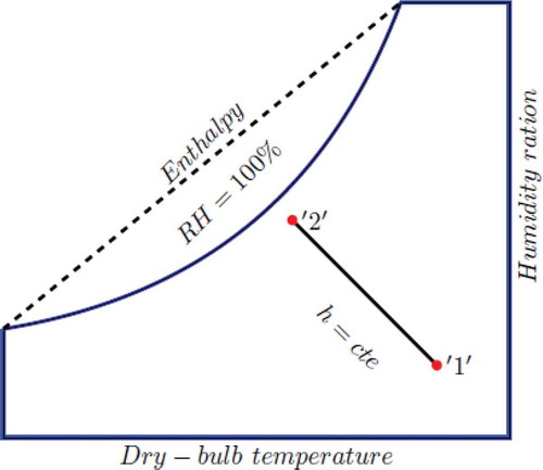
These systems are recognized by their eco-friendly(Kovačević and Sourbron Citation2017) aspect in achieving a cooling effect without any use of chlorofluorocarbons (CFCs) and hydrochlorofluorocarbons (HCFCs) refrigerant and with less power consumption compared to the conventional air conditioner based on the compression of the refrigerant fluid which results in greenhouse gas emission and the ozone layer depletion. The operating principle of a direct evaporative cooling pad (DECP) is based on the adiabatic evaporation of water (Camargo, Ebinuma, and Silveira Citation2005). During this process, as dry air passes through the wet cooling pad its temperature decreases, the humidity increases, the enthalpy remains constant, this change in the state of the air is achieved by the converting a sensible heat containing in the hot air to latent heat of vaporization of water (Camargo, Ebinuma, and Silveira Citation2005; Sohani and Sayyaadi Citation2017). shows the sketch of this process in a psychometrics diagram, the states ‘1ʹ and ‘2ʹ represent the inlet-outlet conditions.
Figure 1. The schematic of the adiabatic evaporation process in the psychrometric chart
These systems are available in the market with different materials and different dimensions, the widely used is the cellulosic corrugated paper cooling pad (CitationMunters). For the countries with low and middle incomes, the cost of the import and shipment may result in a high acquisition cost. To reduce this cost, using a local material is an important option of these countries such as the African countries where these systems are potential and suitable for their climate conditions (Laknizi et al. Citation2019; Tilahun Citation2010; Ndukwu and Manuwa Citation2014).
Recently, various materials have been employed as wetted media; this can result in energy-saving, raising the thermal rating and extending the working life of the equipment (Abohorlu Doğramacı et al. Citation2019). gives a review of some proposed materials that have been experimentally investigated:
Table 1. Literature review of new materials tested experimentally
From the presented literature review, it appears that new materials in the direct evaporative cooler are widely investigated. This work is another attempt to characterize the performance of a new constructed direct evaporative cooling pad made from pottery as local material. The effect of the velocity (volumetric airflow rate) on the saturation efficiency, the cooling capacity, the coefficient of performance, the rate of water consumption, the convective heat and mass transfer coefficient is investigated experimentally.
2. Design and construction of the new cooling pad
Like any pottery equipment, the same steps are followed in the construction of the cooling pad. First, the pottery dough is prepared, then the tubular rods are shaped to the desired dimensions, after that they are exposed to the sun in order to remove the water and finally are fired in an industrial oven.
2.1. Pottery dough preparation
The clay stones are crushed into small irregular fragments and then softened in water for several days. The obtained color of the dough depends on the mineral composition of the clay. Before proceeding with the shaping, the dough is well mixed to remove air bubbles.
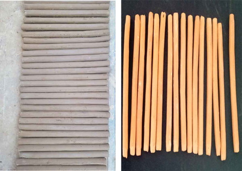
Depending on the desired profile, the dough can be shaped manually or by using a lathe machine. In our case, the profile is simple; tubular rods which are 25 cm long and 2 cm in diameter as shown in .
Figure 2. Pottery rods during the drying phase and after the firing phase
2.2. The assembling and the geometry description
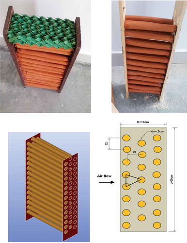
The design and construction of the cooling pad are simple. shows the final assembled geometry which consists of a bundle of tubular pottery rods arranged in a staggered configuration with 3 rows spaced 2 cm apart. Two wooden plates are fixed at each end of the rods by holes to give a rigid shape.
Figure 3. The assembled cooling pad and the details of its geometry
The total number of tubular rods:
The number of tubular rods per row:
The total heat transfer area consists of the area associated with the outside surface of the tubular rods:
The frontal area of the cooling pad
The volume of the cooling pad
Where D is the width, L is the height, L is the length of the tubular rod, do is the diameter of the tubular rod, is the transverse rod pitch and
is the longitudinal rod pitch.
In this section, the new direct evaporation cooling pad has been described in terms of geometry, design, and material. It can be concluded that the DECP built is inexpensive due to the availability of low cost used materials and does not require special machinery or manufacturing processes.
3. Experimental setup
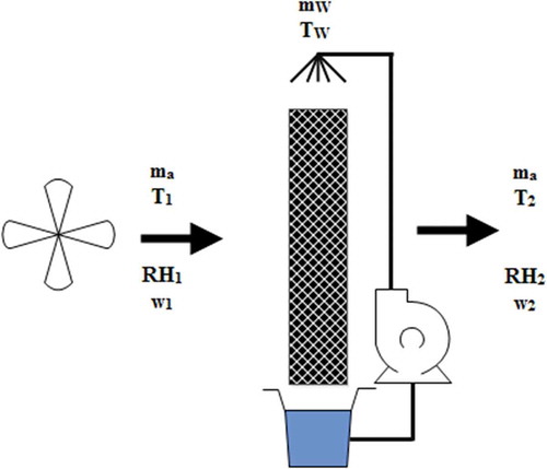
The experimental setup () consists of a constructed wind tunnel equipped with a set of instruments. To assure good distribution of water a cellulosic paper distributor and a sprinkler made of PVC is connected to a pump and is mounted on the top of the pad. A water storage tank is placed on the bottom of the cooling pad to collect the non-evaporating water which flows by gravity through the tubular rods of the pad. An electrical air heater of 2 KW was placed at the inlet of the wind tunnel. To adjust the flow rate, the fan was coupled to a power variation which is installed in the inlet of the wind tunnel.
Figure 4. The experimental setup
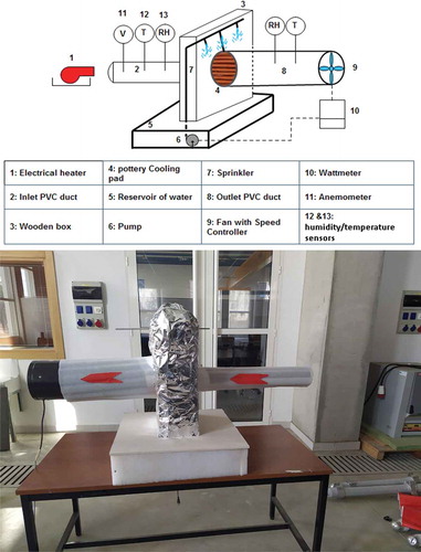
The instruments used in these tests are sensors of temperature/relative humidity connected to two data-loggers to measure the temperature and relative humidity at the inlet/outlet of the wind tunnel. The velocity of the air is measured by propeller anemometer while the electric consumption of the fan and the pump is measured by a power meter. The ranges and the resolution of the used instruments are given in :
Table 2. the characteristics of the instruments
4. The mathematical model and data reduction
Direct evaporation cooling systems incorporate complex phenomena of heat and mass exchange . In this section, a mathematical model is presented, in order to characterize the thermal and the energy performance of the new cooling pad.
Figure 5. The control volume of the direct evaporative cooling pad
4.1. The saturation efficiency
The saturation efficiency is given by the following equation (ASHRAE Citation2015):
Where is the inlet dry bulb temperature,
is the outlet dry bulb temperature and
is the inlet wet bulb temperature.
4.2. The heat balance
The heat balance gives the amount of the cooling capacity that can be delivered by the DECP. It can be calculated by the following equation (Jain and Hindoliya Citation2011):
Where is the inlet dry bulb temperature,
is the outlet dry bulb temperature and
is the inlet wet bulb temperature.
4.3. The coefficient of performance
The coefficient of performance is the ratio between the useful energy (the cooling capacity delivered by the DECP) and the energy supplied (the energy to drive the fan and the pump). It is given by the following equation:
Where q is the cooling effect, Wfan and Wpump are the electrical power consumption of the fan and the pump respectively.
4.4. The mass balance
The dry air during its passage through the cooling pad its humidity increases thanks to the mass transfer of water vapor into the air. This change of the humidity leads to the consumption of a quantity of water which is given by the following equation (Abohorlu Doğramacı et al. Citation2019):
Where ma is the mass airflow, win and wout is the specific humidity at the inlet and the outlet of the cooling pad.
4.5. Heat and mass transfer coefficients
The heat and mass transfer can be deducted from the following equations:
The heat transfer rate is given by:
Where hc is the heat transfer coefficient, Ap is the transfer area, is the logarithmic mean temperature difference.
The logarithmic mean temperature difference is given by(Jain and Hindoliya Citation2011):
The mass transfer rate is given by:
Where hm is the mass transfer coefficient, Ap is the mass transfer area, is the logarithmic mean mass difference
The logarithmic mean mass difference is given by (Jain and Hindoliya Citation2011):
Where ρo and ρi are the mass densities of water vapor in the air stream before and after the cooling pad and ρinwb is the mass density of water vapor at inlet wet bulb temperature.
Based on the measured temperature and humidity, the CoolProp library(Bell et al. Citation2014) and MATLAB were used to extract the thermodynamic properties such as the wet-bulb temperature, the density and the specific humidity of the air.
5. Results and discussion
5.1. Experimental procedure
During the experimental tests, the airflow rate was varied while the water flow rate was kept constant. To assure that the pottery cooler is wetted, the pump was running one hour before starting the record of the temperature and the relative humidity. These data were recorded at one-minute intervals for more than 3 hours, this can help to achieve a steady regime and avoid recording in the transient regime.
shows the recorded data of the considered DECP which are the volumetric airflow rate, the inlet temperature, the inlet relative humidity, the outlet temperature, and the outlet relative humidity and the electrical power consumption of the fan and the pump during each test. Also, show the variation of the outlet temperature and the outlet relative humidity during the test 1, it can be seen from these figures that the outlet temperature and relative humidity remain constant which is a sign of that the steady regime was achieved during the tests.
Figure 6. The evolution of the inlet/outlet temperature during test 1
Figure 7. The evolution of the inlet/outlet relative humidity during test 1
Table 3. The recorded parameters
5.2. The temperature drop
shows the inlet and the outlet temperature with respect to the volumetric airflow rate. It can be seen from this figure that the temperature drop decrease as increasing the velocity. This due to that increasing the volumetric flow rate is equivalent to increase the mass of the load on the cooling pad. In all conducted tests, the temperature drop is between 6.3–7.7°C
Figure 8. The effect of the air volumetric flow rate on the air temperature drop between the inlet and the outlet
5.3. The relative humidity increase
demonstrates the change in the relative humidity with respect to the volumetric airflow rate. It can be seen from this figure that the difference in the relative humidity between the inlet and the outlet decrease as increasing the velocity. The maximum difference is less than 32% which is minimal compared to the commercial DECP. In all conducted tests, the outlet relative humidity is between 61–64% which is within the required comfort conditions.
Figure 9. The effect of the air volumetric flow rate on the change in the relative humidity
In general, the commercial DECP is characterized by the high rise in relative humidity which results in unwanted moisture therefore in uncomfortable feeling. In contrast, in this work, the obtained change of relative humidity is minimal which is an advantage of the current cooling pad.
5.4. The saturation efficiency
shows the variation of saturation efficiency with respect to the volumetric airflow rate. It was calculated using EquationEquation (6)(6)
(6) , as it can be seen from the figure the saturation efficiency decrease as increasing the volumetric flow rate. This result is a common point for all the direct evaporative cooling pad. The scientific reason behind this decrease is that for high volumetric flow rate the contact time between dry air and water is reduced and therefore the mass and heat transfer coefficients are lower. The obtained results indicate that the efficiency is between 56.87 and 49.39.
Figure 10. The effect of the air volumetric flow rate on saturation efficiency
The obtained efficiency is lower compared to those based on fibers and papers materials as shown in . This is due to that the fibres and papers materials have a high rate of water retention than the stones and pottery.
5.5. The cooling capacity
The cooling capacity is another key performance indicator of the DECP. The obtained cooling capacity increase as increasing the volumetric airflow rate as shown in . This due to the fact that the cooling capacity is proportional to the flow rate and temperature drop EquationEquation (7)(7)
(7) . Therefore, any increase in the flow rate will increase the cooling capacity even the temperature drop is small. In contrast, the saturation efficiency will decrease by increasing the flow rate . So, their trends are in opposite direction with respect to the airflow. The obtained cooling capacity of the current cooling pad is between 273.76–539.7 W.
Figure 11. The effect of the air volumetric flow rate on the cooling capacity
5.6. The rate of water consumption
In the conventional air conditioner, a refrigerant is used as a thermal agent to absorb and reject heat. These refrigerants pollute the environment and they have a high global warming impact. In contrast, the direct evaporative cooling pad uses water as the refrigerant fluid which makes to considered the DECP as ecological solutions. demonstrates the effect of the volumetric airflow rate on the amount of water consumption. It can be seen from this figure that the rate of water consumption increase with increasing the volumetric airflow rate. This trend towards increased water consumption is due to the fact that increasing the airflow while maintaining a constant water flow makes it more probable that a droplet of water will evaporate by the dry air. In other word, high velocity enhances the evaporation of water which directly causes an increase in the amount of water consumption.
Figure 12. The effect of the air volumetric flow rate on the rate of water consumption
The obtained results show that the amount of water consumed during the cooling process is between 0.35 and 0.84 kg h−1, which is equivalent to 0.097 and 0.233 gr s−1. For the same range of the mass flow rate, an evaporation rate between 0.12 and 0.303 gr s−1 is reported on Eucalyptus fiber cooler (Abohorlu Doğramacı et al. Citation2019). This comparison shows that the values of the pottery cooler are minimal compared to the value of the Eucalyptus fiber.
5.7. The coefficient of performance
shows the effect of the volumetric flow rate on the coefficient of performance. The obtained COP is between 7.8 and 8.8 which is more than the double of the COP of the conventional split air conditioner. This comparison is based on the fact that the conventional residential split air conditioners have a COP does not exceed 3 (Hu and Huang Citation2005). Also, these results confirm the ecological aspect of the DECP by consuming less electrical power and therefore rejecting fewer greenhouse gases to the environment.
Figure 13. The effect of the air volumetric flow rate on the coefficient of performance
The COP of the current pottery cooler is maximal compared to of the Eucalyptus fiber direct evaporative cooler which is between 2.55 and 3.93 (Abohorlu Doğramacı et al. Citation2019).
5.8. The heat and mass transfer coefficient
show the variation of heat and mass transfer coefficients against the volumetric flow rate. The DECP incorporating coupled phenomena of heat and mass exchange. The heat and mass transfer coefficients depend on many factors such as the media of the pad, the dimension of the pad (thickness, height, and width) and the velocity (Liao and Chiu Citation2002). This dependence is generally expressed in the form of mathematical correlations that can be found in the handbooks of heat and mass transfer. The experimental results on the current new DEPC show that both the coefficients increase as increasing the volumetric airflow rate which is in good agreement with the existent results in the literature obtained on the commercial and the cooling pad based on new material (Jain and Hindoliya Citation2011).
Figure 14. The effect of the air volumetric flow rate on the heat transfer coefficient
Figure 15. The effect of the air volumetric flow rate on the mass transfer coefficient
summarizes the obtained results:
Table 4. the summary of the obtained experimental results
The uncertainty analysis was performed to find the errors. The overall uncertainty can be expressed as follow:
Where R is a function of the measurable parameters (xi) EquationEquation (16)(16)
(16) . In our case, the measurable parameters are the temperature, the relative humidity and the velocity of the air.
is the uncertainty of the measurables parameters.
The relative uncertainty can be obtained by:
Example of the saturation efficiency, the expression of the overall uncertainty is:
gives the relative uncertainty of the tests.
Table 5. The results of the uncertainty analysis
6. Conclusion
This work presents an experimental analysis of a new direct evaporative cooling pad based on pottery material. The effect of the velocity (volumetric airflow rate) on the performances of this system was examined. Under the investigated conditions, the main research outputs of the current work are:
The temperature reduction between the inlet and the outlet is between 6.4 and 7°C
The increase in the relative humidity is between 28.37 and 31.7 %
The saturation efficiency is between 49.4 and 65.87%
The cooling capacity ranges from 273.76 to 539.7 W.
The coefficient of performance is between 7.8 and 8.8.
The proposed cooling pad is energy efficient and can be used as a replacement to the conventional air conditioner.
The availability and the low cost of the used material are significant features.
To enhance the cooling efficiency of the current cooling pad, the pottery rod must be fired at low temperature to obtain a high porosity rate and not reach vitrification (porcelain), which consequently improves the rate of retention of the water.
Nomenclature
| Latin symbols | = | |
| Ap | = | Heat transfer area, m2 |
| Cp | = | Specific heat capacity, J kg−1 K−1 |
| D | = | Thickness of Pad, mm |
| h | = | Enthalpy, kJ kg−1 |
| hc | = | Convective heat transfer coefficient, W m-2 K−1 |
| hm | = | Convective mass transfer coefficient, m s−1 |
| L | = | Height of the pad, mm |
| l | = | Width of the pad, mm |
| m | = | Mass flow rate, kg s−1 |
| q | = | Cooling capacity of the pad, W |
| RH | = | Relative humidity, % |
| Tid | = | Inlet dry temperature, K |
| Tod | = | Outlet dry temperature, K |
| U | = | Relative uncertainty, % |
| V | = | Velocity, m s−1 |
| Wfan | = | Power consumption of the fan, W |
| Wpump | = | Power consumption of the pump, W |
| Wi | = | Specific humidity at the inlet, kgw kgda−1 |
| Wo | = | Specific humidity at the outlet, kgw kgda−1 |
| Greek symbols | = | |
| η | = | Effectiveness,% |
| ρ | = | Density, kg m−3 |
| σ | = | |
| Subscripts | = | |
| e | = | Evaporated |
| od | = | Outlet dry |
| id | = | Inlet dry |
| inwb | = | Inlet wet bulb |
Acknowledgments
The authors would like to express their appreciation to ‘‘IRESEN” for providing financial support to carry out this research. We would also like to thank Mr. Kamal Anoune for his support in the construction of the experimental setup.
Disclosure statement
No potential conflict of interest was reported by the authors.
Additional information
Funding
Notes on contributors
Azzeddine Laknizi
Azzeddine Laknizi is a graduate of Energy Engineering from the Faculty of sciences and techniques (FST) of Mohammedia Morocco. He is currently a lecturer and researcher in the “aerospace engineering school” of Rabat International University, Morocco. In 2014 he has received a scholarship from the Research Institute for Solar Energy and New Energies (IRESEN) to support his doctoral dissertation. His Ph.D. thesis and research interests focus on the areas of thermal energy, Heating, Ventilation, and Air-Conditioning.
Abdellatif Ben Abdellah
Abdellatif Ben Abdellah holds a master’s degree in physics engineering from Lorraine University (Metz), France and received in 1994 his Ph.D. in liquid alloys transport properties from the same university with a thesis on Contribution to study the electronic transport properties of manganese liquids alloys and atomic transport of Gallium-Lead liquid presented a miscibility gap. In 2009, he received D. Phil (Doctorat d’état) from Abdelmalek Essaadi University on a thesis “Contribution to study the electronic and atomic transport properties of gallium - lead liquid alloy presented a miscibility gap”. His research area is in the physics of condensed matter, he investigates the electronic properties of liquid metals, from the experimental and theoretical point of view. He has published over 50 articles in international journals. He held many invited consultant/ visiting professor at Physics and Dense Matter Lab (France) and, Sultan Qaboos University (Oman).He has more than a hundred patents. He received several national and international prizes in the innovation and research and development field. In 2007 he was awarded the first prize in the “Made in Arabia World Competition”. He received the Best Researcher prize at Abdelmalek Essaadi University in May 2009. Currently, he is a professor at Mechanical Engineering at the College of Sciences and Techniques of Tangier, and consultant at R&D platform of Rabat International University, Morocco.
Mustapha Faqir
Mustapha Faqir is currently an associate professor and academic director in the “aerospace engineering school” of Rabat International University, Morocco. He received his Ph.D. degree in electronics engineering, jointly from the University of Bordeaux 1, France, and the University of “Modena e Reggio Emilia”, Italy, working on the processing, characterization, modeling, and reliability of III-V based transistors and LEDs for lighting and RF power applications. He was with MD Micro detectors, Italy, where he worked on sensors design for four years as an R&D Engineer and then as a consultant. For two years, he has been working as a researcher in the Center for Device Thermography and Reliability (CDTR) at the University of Bristol, UK, with a lead position in two main projects: 1- Advanced materials for power electronics packaging (thermal and mechanical characterization, FEA, failure analysis…), with the aim of establishing an aerospace compatible European supply chain (consortium: Uni. of Bristol, Thales Alenia Space, CNES, Egide, Plansee, UMS, Tecnalia); 2- Reliability and failure analysis of GaN HEMTs (consortium: Uni. of Bristol, MIT, UCSB,Triquint). At UIR, he is involved in many projects in the fields of desalination, CPV, solar farm monitoring, Lithium-ion batteries, and advanced materials for aeronautics. His research interests include the study and the analysis through experimental techniques and numerical simulations of failure modes, thermal & thermo-mechanical characterization and modeling of different materials for microelectronics devices and packaging, as well as materials for aerospace applications.
Elhachmi Essadiqi
Elhachmi Essadiqi is currently Dean of Aerospace Engineering school at the Université Internationale de Rabat, Morocco and adjunct professor at Mississippi State University. His main research interests are in the area of lightweight materials for automotive and aeronautics applications (e.g. Al-Li); microstructure and properties relationship in ferrous and non-ferrous alloys. Dr. Essadiqi developed a twin-roll casting process and design thermo-mechanical processes for new magnesium – RE alloys sheet, in collaboration with General Motors, Novelis, MagNET (a network of excellence of 5 Canadian Universities) and Helmholtz Geesthacht Zentrum (old GKSS) in Germany. He is now working on seawater desalination using solar energy and recycling of solid materials such as steel and Mg alloys.
Said Dhimdi
Said Dhimdi is a Doctor of Science. He is currently a professor of applied thermodynamics, hydraulics and pneumatics at the IEPS in Uccle.
References
- Alodan, M. A., and A. A. Al-Faraj. (2005). “Design and Evaluation of Galvanized Metal Sheets as Evaporative Cooling Pads.” Journal of King Saud University Agricultural Science 18 (1): 9–18.
- Abohorlu Doğramacı, P., S. Riffat, G. Gan, and D. Aydın. 2019. “Experimental Study of the Potential of Eucalyptus Fibres for Evaporative Cooling.” Renewable Energy 131: 250–260. doi:10.1016/j.renene.2018.07.005.
- Ahmed, E. M., O. Abaas, M. Ahmed, and M. R. Ismail. 2011. “Performance Evaluation of Three Different Types of Local Evaporative Cooling Pads in Greenhouses in Sudan.” Saudi Journal of Biological Sciences 18 (1): 45–51. doi:10.1016/j.sjbs.2010.09.005.
- Aljubury, I. M. A., and H. D. Ridha. 2017. “Enhancement of Evaporative Cooling System in a Greenhouse Using Geothermal Energy.” Renewable Energy 111: 321–331. doi:10.1016/j.renene.2017.03.080.
- Al-Sulaiman, F. 2002. “Evaluation of the Performance of Local Fibers in Evaporative Cooling.” Energy Conversion and Management 43 (16): 2267–2273. doi:10.1016/S0196-8904(01)00121-2.
- ASHRAE. 2015. ASHRAE Standard 133-2015: Method of Testing Direct Evaporative Air Coolers.
- Bell, I. H., J. Wronski, S. Quoilin, and V. Lemort. 2014. “Pure and Pseudo-pure Fluid Thermophysical Property Evaluation and the Open-source Thermophysical Property Library CoolProp.” Industrial & Engineering Chemistry Research 53 (6): 2498–2508. doi:10.1021/ie4033999.
- Bishoyi, D., and K. Sudhakar. 2017. “Experimental Performance of a Direct Evaporative Cooler in Composite Climate of India.” Energy and Buildings 153: 190–200. doi:10.1016/j.enbuild.2017.08.014.
- Camargo, J. R., C. D. Ebinuma, and J. L. Silveira. 2005. “Experimental Performance of a Direct Evaporative Cooler Operating during Summer in a Brazilian City.” International Journal of Refrigeration 28 (7): 1124–1132. doi:10.1016/j.ijrefrig.2004.12.011.
- Davies, P. A., A. K. Hossain, and P. Vasudevan. 2009. “Stand-alone Groundwater Desalination System Using Reverse Osmosis Combined with a Cooled Greenhouse for Use in Arid and Semi-arid Zones of India.” Desalination and Water Treatment 5 (1–3): 223–234. doi:10.5004/dwt.2009.520.
- Dhamneya, A. K., S. P. S. Rajput, and A. Singh. 2018. “Thermodynamic Performance Analysis of Direct Evaporative Cooling System for Increased Heat and Mass Transfer Area.” Ain Shams Engineering Journal 9 (4): 2951–2960. doi:10.1016/j.asej.2017.09.008.
- Elattar, H. F., A. Fouda, and S. A. Nada. 2016. “Performance Investigation of a Novel Solar Hybrid Air Conditioning and Humidification–Dehumidification Water Desalination System.” Desalination 382: 28–42. doi:10.1016/j.desal.2015.12.023.
- Gunhan, T., V. Demir, and A. K. Yagcioglu. 2007. “Evaluation of the Suitability of Some Local Materials as Cooling Pads.” Biosystems Engineering 96 (3): 369–377. doi:10.1016/j.biosystemseng.2006.12.001.
- Hu, S. S., and B. J. Huang. 2005. “Study of a High Efficiency Residential Split Water-cooled Air Conditioner.” Applied Thermal Engineering 25 (11): 1599–1613. doi:10.1016/j.applthermaleng.2004.11.011.
- Jain, J. K., and D. A. Hindoliya. 2011. “Experimental Performance of New Evaporative Cooling Pad Materials.” Sustainable Cities and Society 1 (4): 252–256. doi:10.1016/j.scs.2011.07.005.
- Jradi, M., and S. Riffat. 2016. “Testing and Performance Analysis of a Hollow Fiber-based Core for Evaporative Cooling and Liquid Desiccant Dehumidification.” International Journal of Green Energy 13 (13): 1388–1399. doi:10.1080/15435075.2016.1183205.
- Kabeel, A. E., and M. M. Bassuoni. 2017. “A Simplified Experimentally Tested Theoretical Model to Reduce Water Consumption of A Direct Evaporative Cooler for Dry Climates.” International Journal of Refrigeration 82: 487–494. doi:10.1016/j.ijrefrig.2017.06.010.
- Kovačević, I., and M. Sourbron. 2017. “The Numerical Model for Direct Evaporative Cooler.” Applied Thermal Engineering 113: 8–19. doi:10.1016/j.applthermaleng.2016.11.025.
- Laknizi, A., M. Mahdaoui, A. B. Abdellah, K. Anoune, M. Bakhouya, and H. Ezbakhe. 2019. “Performance Analysis and Optimal Parameters of a Direct Evaporative Pad Cooling System under the Climate Conditions of Morocco.” Case Studies in Thermal Engineering 13: 100362. doi:10.1016/j.csite.2018.11.013.
- Liao, C.-M., and K.-H. Chiu. 2002. “Wind Tunnel Modeling the System Performance of Alternative Evaporative Cooling Pads in Taiwan Region.” Building and Environment 37 (2): 177–187. doi:10.1016/S0360-1323(00)00098-6.
- Manuwa, S. I., and S. O. Odey. 2012. “Evaluation of Pads and Geometrical Shapes for Constructing Evaporative Cooling System.” Modern Applied Science 6 (6): 45. doi:10.5539/mas.v6n6p45.
- Martínez, P., J. Ruiz, P. J. Martínez, A. S. Kaiser, and M. Lucas. 2018. “Experimental Study of the Energy and Exergy Performance of a Plastic Mesh Evaporative Pad Used in Air Conditioning Applications.” Applied Thermal Engineering 138: 675–685. doi:10.1016/j.applthermaleng.2018.04.065.
- Munters. “Evaporative Cooling Pad (model: CELdek® 7090-15).”https://www.munters.com/
- Ndukwu, M. C., and S. I. Manuwa. 2014. “Review of Research and Application of Evaporative Cooling in Preservation of Fresh Agricultural Produce.” International Journal of Agricultural and Biological Engineering 7 (5): 85–102.
- Sohani, A., and H. Sayyaadi. 2017. “Design and Retrofit Optimization of the Cellulose Evaporative Cooling Pad Systems at Diverse Climatic Conditions.” Applied Thermal Engineering 123: 1396–1418. doi:10.1016/j.applthermaleng.2017.05.120.
- Tilahun, S. W. 2010. “Feasibility and Economic Evaluation of Low-cost Evaporative Cooling System in Fruit and Vegetables Storage.” African Journal of Food, Agriculture, Nutrition and Development 10 (8). doi:10.4314/ajfand.v10i8.60885.
- Xu, J., Y. Li, R. Z. Wang, W. Liu, and P. Zhou. 2015. “Experimental Performance of Evaporative Cooling Pad Systems in Greenhouses in Humid Subtropical Climates.” Applied Energy 138: 291–301. doi:10.1016/j.apenergy.2014.10.061.