Abstract
In the Netherlands, wide-scale implementation of cogeneration of electricity and heat substantially reduces primary energy use and CO2 emissions. However, gas engines of cogeneration installations in the greenhouse horticultural sector alone are already responsible for a methane emission of roughly 1 Megatonne of CO2-equivalents. This amount has been determined by a series of measurement programmes as ordered by the Dutch Ministry of Infrastructure and Environment. This Ministry aims at reducing that methane slip, amongst others by setting legal emission limit values and stimulating engine innovations. However, the data from those measurement studies neglect important underlying causes of the emissions. Therefore, they are likely to be insufficiently conclusive for policy-making. In this paper, the most important causes of hydrocarbon emissions of combined heat and power (CHP) engines in relation to their design and process conditions have been assessed. An important finding is that a simple approach of just registering the output of measurement instruments and reporting these holds a high risk of methodological errors and neglected causes leading to inappropriate conclusions and subsequently inadequate policies. Overall, the paper not only contributes to the academic understanding of the qualifications and quantifications of these emissions, but also to the relevant policy-making in this field.
1. Introduction
Greenhouse-based horticulture companies in the Netherlands extensively use combined heat and power (CHP) installations for the production of electricity, heat and CO2. The heat released by the gas engines that drive the generators is used to create a temperature in the greenhouses for optimum crop growth. The electricity produced is used for artificial lighting of the greenhouses, the so-called assimilation lighting. During times of peak demand of electricity however, the CHP units can profitably supply the electricity produced into the public grid. The CO2 resulting from the combustion process in the engines is used to increase the CO2 concentration in the greenhouse. This so-called CO2 fertilisation also results in a higher crop yield. The CHP concept is economically attractive and results in a return of investments within approximately five years.
Because of their optimum fuel utilisation from a national point of view, CHP installations are widely promoted by market parties and governments. An efficient fuel utilisation also results in low specific CO2 emissions. However, as with any combustion system, there are several environmental aspects to CHP-engines which need further attention. An important aspect concerns the emission of methane in conjunction with NOx. This aspect will be elaborated in this paper.
Emissions data of spark-ignited gas engines showed that between 1 and 3% of the fuel hydrocarbons (HCs) escape the combustion process and end up in the flue gas. These HCs consist mostly of methane, a strong greenhouse gas having a global warming potential (GWP) of 23Footnote1. This means that methane has a greenhouse effect per unit of mass 23 times higher than that of CO2. Over the total greenhouse horticulture sector in the Netherlands, this so-called methane slip already exceeds 1 Megatonne of CO2-equivalent (van der Maas et al. 2010). From the perspective of environmental and climate policy, it is imperative to reduce this methane slip. In this context, the mechanism of hydrocarbon slip in gas engines must be fully understood. The engine sector has already made progress in the abatement of hydrocarbon emissions (van der Maas et al. 2010), but further research is needed.
The Ministry of Infrastructure and Environment (I&M) of The Netherlands and NL Agency aim to reduce to total amount of greenhouse gas emissions in the Netherlands. In that context, they charged KEMA to carry out two measurement programmes in 2007 and 2009. Both programmes aimed to measure the hydrocarbon (HC) emissions of a number of engines and deduce the methane slip fractions from them (Olthuis et al. Citation2007, 2009). The results of the measurements were used as a guideline for an initial limit of 1500 mg C/m3 at 3% O2 (dry) in the Dutch Decree on emission regulation mid-sized combustion plants (BEMS) (Citation2009). Further, it was hoped that the measurement data would provide insight into trends in HC emissions dependent upon typical engine parameters. That might give indications on how to further reduce these emissions. However, the 2007 and 2009 measurements revealed many uncertainties with respect to possible influences of the process parameters of the engines on the emissions. Therefore, a new series of measurements was initiated in 2011. This paper presents and discusses these measurements and explains the mechanisms that lead to HC emissions from gas engines.
2. Origins of hydrocarbon emissions from gas engines
Internal combustion engines based on the so-called Otto cycle draw a mixture of fuel gas and air into the cylinders during the intake stroke and ignite this combustible mixture after compressing it by the pistons. Four main reasons exist why the fuel gas is not completely oxidised in such an engine:
| • | Combustible mixture in the crevices (the gaps) in the combustion chamber that escapes the combustion process; | ||||
| • | Combustible mixture that escapes via the exhaust valves when both intake and exhaust valves are open during the gas exchange process; | ||||
| • | Misfiring, i.e. fully incomplete combustion caused by a malfunctioning ignition system; | ||||
| • | Incomplete combustion with a mixture that is too lean in fuel or insufficient homogenous. | ||||
2.1. Crevices
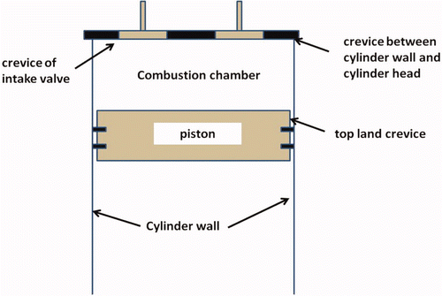
Crevices are narrow gaps in the combustion chamber in which combustible mixture is pushed during the compression process. Figure 1 concerns the scheme of a combustion chamber in which also the crevices are clearly indicated. These gaps areso narrow that the flame front cannot progress into them. The cool walls of thecrevices are the cause of quenching the chemical reaction. The contents of the crevices return to the combustion chamber during the expansion process in the engine, when the pressure in the cylinders rapidly decreases. However, the process conditions when that happens are unfavourable for combustion. Therefore, most of the unreacted hydrocarbons will leave the cylinder during the exhaust process and end up in the environment.
Engine designers strive continuously to minimise crevice volumes. They successfully reduced the crevices between the intake and exhaust valves and their respective seats to an insignificant size. Also the crevice between cylinder head and cylinder liner has been reduced as far as possible. The only significant remaining crevice is the so-called top-land crevice between piston and cylinder above the top compression ring. This crevice cannot be reduced to zero because it is an essential element of the piston lubrication system. The lubricating oil should not exceed a temperature of roughly 170°C, since that would lead to deterioration of the oil and build up of carbon deposits in the top-ring area. The only way to protect the oil from the high temperatures in the combustion chamber is flame quenching in the top-land crevice. Naturally, one strives to narrow the crevice as much as possible, but sufficient clearance should remain so that the piston crown will not touch the cylinder wall.
2.2. Valve overlap
Fresh combustible mixture has to enter the cylinders of the engine after the typical engine cycle has been completed. Before that, the combustion end products, i.e. the exhaust gas, has to leave the cylinders. At the end of the expulsion stroke where the exhaust gas is pushed out of the cylinders, the exhaust valve is still partly open while the intake valve opens to let fresh mixture in. Especially with turbocharged engines, where the pressure in the intake system sometimes exceeds the pressure in the cylinder during the exhaust stroke, fresh mixture might escape via the exhaust valves. Modern engines however are designed in such a way that this does not take place anymore. Fresh mixture can nowadays only directly escape via the exhaust if the valve clearance is too small, resulting in partly open valves during the engine cycle. This can be prevented by timely and correctly performing maintenance actions.
2.3. Misfiring
Correct ignition of the combustible mixture during each cycle is crucial in avoiding high hydrocarbon emissions. Failure to ignite the mixture results in very high emissions and can even be the cause of dangerous situations with excessive amounts of explosive mixture in the engine exhaust system. Ignition failure occurs in case of defective spark plugs, broken high-voltage ignition coils, bad contacts and a malfunctioning control system. Primarily because of the risk of exhaust explosions, most modern engines have been equipped with a permanent system checking ignition from cycle to cycle. The costs of such a monitoring system are relatively small, especially when considering the negative consequences of an explosion.
2.4. Very lean mixtures
The air-to-fuel ratio of combustible mixtures cannot be increased too much. So-called fuel-lean, or simply lean, mixtures help to improve the thermodynamic efficiency of the engine cycle. This is caused by lower heat losses, better medium properties and a lower tendency to combustion knock. Moreover, the low peak temperature in connection with lean mixtures drastically reduces the NOx production of engines. Since large-bore engines have relatively less heat losses from the cylinder contents than engines with a smaller bore due to their lower area–volume ratio, the peak temperatures in the cylinders of larger bore engines are higher for a given air-to-fuel ratio. Therefore, for the same specific NOx production large-bore engines have to operate on leaner mixtures than small-bore engines.
Large lean-burn engines generally have prechambers in which a relatively rich mixture is ignited; the hot jets emerging from the prechambers ignite the ultra-lean mixture in the main chamber. Such prechambers are needed to ignite such a lean mixture, since the energy released by a spark-plug only is insufficient to initiate stable combustion. If the prechamber is relatively large, the NOx produced in the prechamber can determine a substantial part of the total NOx emission of the engine. In that case, the mixture in the main chamber has to be extra lean to compensate for the high NOx production of the prechamber. Mixtures that are too lean are sensitive to misfiring and can suffer from local pockets of mixture leaving the engine without combustion (Dyer Citation1985; Klimstra Citation1990; Hicks et al. Citation1996; Euromot Citation2010). This is especially the case when the homogeneity of the combustible mixture is not perfect.
3. Initial programme for the measurement of the hydrocarbon emissions of a range of different engines
The first series of measurements to determine the hydrocarbon emissions of gas engines on behalf of the Ministry I&M was carried out by KEMA in 2007. This series comprised a total of 10 engines, representing the most common makes and types as applied in cogeneration systems.Footnote2 Expectations were that the HC emissions might deteriorate by ageing of the engines. The scatter in HC emissions from engine to engine appeared to be rather high. Therefore, the Ministry initiated a second series of tests in 2009. Eight of the engines measured in 2007 were investigated again in 2009. Moreover, an additional 22 installations were tested in order to increase the statistical representativeness of the results.
The volumetric HC concentration in the exhaust gas was measured by taking a continuous sample stream from the exhaust gas and leading this to a flame ionisation detector (FID). Using a FID is prescribed in BEMS. This FID monitor was calibrated with propane (C3H8) in conformity with BEMS. In addition, the concentration of oxygen (O2), carbon monoxide (CO) and oxides of nitrogen (NO and NOx) was determined in a dried sample stream of the flue gas. All measurements were carried out at rated load (name plate load) of the cogeneration installations. In case an exhaust gas after-treatment system was present at the installation, only the species concentrations downstream of the exhaust gas after-treatment system were measured. It will be clear that the species concentrations as measured after the exhaust gas after-treatment system are not representative for the engine-out concentrations. The exhaust gas after-treatment system substantially reduces the CO and NOx concentrations, and it also oxidises part of the non-methane hydrocarbons. As a consequence, measurement data of engines with or without exhaust gas after-treatment systems cannot be compared. Special hydrocarbon measurements carried out during the 2007 tests with a gas chromatograph, all taken downstream of an exhaust gas after-treatment system, revealed an average methane fraction in the HC emissions of 93% on a mass basis. This 93% fraction was further used for calculating the methane emissions from the HC emissions measured from the FID. The 93% methane on a mass basis is slightly higher than 91.6% the mass fraction of methane in the total hydrocarbons of the typical Groningen composition of natural gas. The literature shows that the fraction of hydrocarbon species in the fuel can be used as a first approximation for the species concentrations in the engine exhaust (Dyer Citation1985; Klimstra Citation1990; Hicks et al. Citation1996; Euromot Citation2010). However, it will be clear that the methane fraction will be higher in case the measurement takes place downstream of an exhaust gas after-treatment system that removes higher hydrocarbons. In addition, the fuel composition will affect the methane fraction.
The measured volumetric concentrations of hydrocarbons have been converted to mg C/m3 at 3% O2 (dry). The reason for this is that the Ministry uses the 3% O2 (dry) reference in their emission legislation. The use of this unit hampers however a direct comparison with data in international publications and can create confusion. Using mg HC/m3 at 15% O2, or g/GJ (fuel input-based) and g/kWh (energy output-based) is common practice. The actual oxygen percentage in dried exhaust gas of modern gas engines ranges between 8.5 and 11%. Based on the composition and energy content of Groningen-type fuel gas, 1000 mg C/m3 at 3% O2 roughly compares with 285 g C/GJ and 380 g CH4/GJ (Geerssen Citation1988).
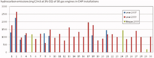
shows the large variation in HC emissions from engine to engine. Engine 29 is a naturally aspirated engine running on bio gas. This engine is not representative for modern turbocharged gas engines. The averaged HC emission of the 30 engines as measured during a time span of 30 min ranges from 605 mg C/m3 to 2643 mg C/m3, all converted to an oxygen concentration in the exhaust of 3% (dry). Only two of the five engines with HC emissions exceeding 1500 mg C/m3 in 2009 were prechamber engines. Therefore, the idea that prechamber engines especially have high HC emissions had to be abandoned.
Figure 2. Overview of the total hydrocarbon emissions of 30 different gas engines as measured by KEMA in 2009, in combination with 8 engines measured in 2007 (Olthuis et al. 2009).
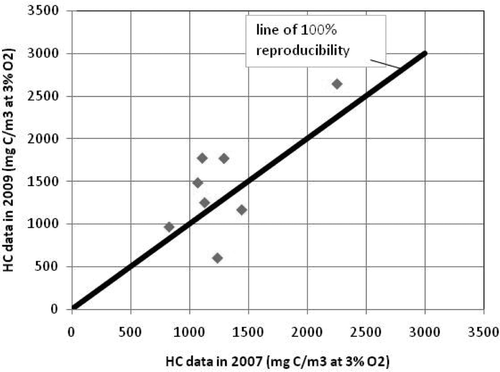
The reproducibility of the HC emissions of the eight engines that had been tested in 2007 as well as in 2009 deserves special interest. The results are given in .
Of the eight engines tested in 2007 as well as in 2009, only one engine had significantly lower HC emissions in 2009 than in 2007. This was engine 8 that had been modified before the second tests: the prechambers were replaced by a low emission type, while the aluminium pistons were replaced by steel ones. This action seemed quite successful, since the HC emissions more than halved, from 1239 to 605 mg C/m3. Engine 21 showed a lower decrease, from 1445 to 1170 mg C/m3 at 3% O2 or almost 20% decrease. Three of the eight engines however showed a significant increase in HC emissions, ranging from 37% to 60%. The observed changes in HC emissions were that closer research into the underlying cause was deemed necessary.
Many references presume that higher HC emissions are directly related with a leaner mixture (Dyer Citation1985; Klimstra Citation1990; Hicks et al. Citation1996; Euromot Citation2010). Therefore, the HC emission of the engines of the 2009 test series was plotted as a function of the measured oxygen concentration (). It is apparent from that the 2009 results combined do not show a significant rise in HC emissions for a higher oxygen concentration in the exhaust gas. The red linear trend line in slightly increases with oxygen concentration, but this is primarily caused by engine 2 which clearly is an outlier. The correlation coefficient is just 0.2, indicating again a poor relationship between HC emissions and oxygen concentration in the exhaust gas. If the high HC emission from engine 2 is omitted, the correlation coefficient is just 0.06.
Figure 4. Hydrocarbon emission of the gas engines as measured during the second series of measurements (2009) plotted against the measured oxygen concentration (dry) in the exhaust gas. (engines A, etc. are of the same make; engines Ea are of the same type; PC means prechamber).
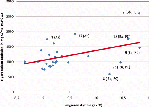
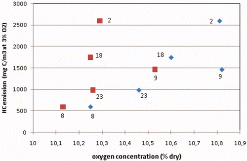
However, the three prechamber engines 8, 9 and 23 are of the same make and type. When considering these three engines as identical, a close to linear relationship between the HC emission and the measured oxygen concentration is seen. This might indicate that for an individual engine, a leaner mixture strongly increases the HC emissions. Before this conclusion can be drawn, one has to bear in mind that for a fixed air-to-fuel ratio lambda (λ), higher hydrocarbon emissions also mean that less oxygen from the combustible mixture is consumed. Therefore, to reveal the relationship between HC emissions and the air-to-fuel ratio λ, one has to correct the measured oxygen concentration for the oxygen not consumed by the unburned hydrocarbons. This correction has been carried out for the three engines of the same type 8, 9 and 23, as well as for engines 2 and 18 which are of the same make but not the same type. shows that the positive trend between the HC emissions and the net oxygen concentration in the exhaust for engines 8, 9 and 23 is still present after this correction. Comparing the HC emissions of engines 23, 18 and 2, all running at a net oxygen concentration of about 10.3%, proves that easily a factor 2.5 in HC emissions for about the same net oxygen concentration can exist between different engine makes and engine types. The same variation in HC emissions is seen in for the lower oxygen range between 9.0 and 9.5%.
Figure 5. HC emissions of five engines measured in 2009 plotted against measured oxygen concentration in the exhaust (blue diamonds) and against net oxygen concentration (red blocks); Engines 8, 9 and 23 are of an identical design.
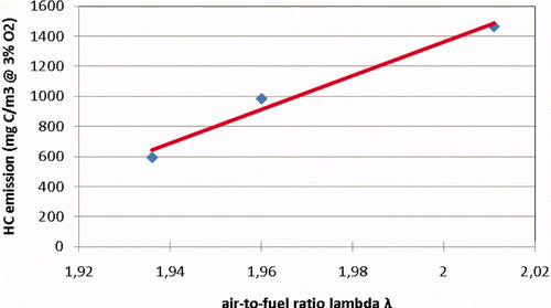
illustrates again the dependence of the HC emissions of the identical-type prechamber engines 8, 9 and 23 on mixture strength, now plotted against the air-to-fuel ratio λ. Apparently, the completion of the combustion process of these engines is very sensitive to the air-to-fuel ratio. Unfortunately, the NOx emission of these engines had been measured downstream of the catalytic exhaust gas after-treatment system. The emissions value is not representative for the NOx production by the engine. The NOx production is an indicator of the peak temperatures in the combustion process and that might help in explaining any deviations in engine tuning.
4. Summarising discussion of the 2007 and 2009 measurement programmes
The 2007 and 2009 measurement programmes showed a relative wide variation of HC emissions and their methane fractions. According to the results of the 2009 programme, 80% of the 30 measured CHP-engines operated within the BEMS emission limit value (ELV) of 1500 mg C/m3 0 at 3% O2 for HCs. Some of the CHPs that were compliant to that ELV in the 2007 measurement programme failed to meet the limits in 2009. A first conclusion was that CHP performance and emissions could not yet be guaranteed over time and could even divert relative strongly from the manufacturer's specifications. A workshop was held on 3 January 2010, in which engine specialists and CHP suppliers discussed the results with representatives from the Ministry I&M and NL Agency. It was concluded that the carried out measurement programmes provided a clear overview of the level of HC emissions. However, no solid conclusions could be drawn concerning the causes of the variations due to the large number of unknown process parameters. Explanations for the variations needed to be sought via an additional series of measurements. Such tests should include more engine parameters in order to reveal relationships of the sensitivity of the CHP units to such parameters. Since manufacturers cannot prescribe the typical process parameters as applying to the installations of the users, specific knowledge of the mentioned sensitivities is required prior to further relevant policy-making. It was expected to identify possible emission reduction options from the new test programme.
At the end of 2010, the Ministry I&M and NL Agency launched a new measurement programme to that purpose, which KEMA carried out in 2011. This programme assesses the relevant parameters and process conditions in relation to performance and methane slip of the CHP engines. Important process parameters such as temperature of the combustible mixture in the intake manifold, combustion stability and the occurrence of misfiring will then be measured. Also specific fuel consumption will be measured accurately, since the resulting energy conversion efficiency might explain deviating engine performance. For the 2007 and 2009 programmes, many HC measurements had been taken downstream of the exhaust gas after-treatment system. It has been explained already that such a system has an oxidation catalyst that removes large part of ethene (C2H4) and hydrocarbons higher than C2. Current oxidation catalysts have difficulty in oxidising methane and even ethane at the given exhaust temperatures between 380°C and 450°C (de Wit et al. Citation2005). Besides the total HC emissions, the methane concentration can also be directly measured with a dedicated detector. This will provide information about the actual fraction of the methane emissions in the total HC emissions. Ten highly representative CHPs will be measured in two different seasons, namely in spring and in autumn/winter. This will help to determine the impact of seasonal influences affecting the process conditions of CHPs with possible consequences for emissions. Due to budget restrictions, only 10 different installations will be investigated. In case of the presence of an exhaust gas after-treatment system, the species concentrations in the exhaust gas will be measured both upstream and downstream of the catalyst. The upstream data will reveal the engine-out emissions while the data downstream of the catalyst will give the effectiveness of the catalysts to reduce NOx, CO and total hydrocarbons.
5. Preliminary results of the first measurement series of 2011
The first series of the measurement series scheduled for 2011 has already been carried out. The measured data show very interesting results. However, due to the amount of data and the many interrelationships between the different quantities, the analysis and reporting are still under progress. Yet, some crucial first observations will be provided below.
5.1. The measured fraction of methane in the hydrocarbons
In its 2007 and 2009 reports on the emission data, KEMA presented the methane emissions based on a fraction of 93% of the measured HC emissions. However, in the 2011 first series of tests, the measurement of the methane concentration separate from the HC concentration gave much lower methane fractions than the 93%. shows that a methane mass fraction of even less than 75% was measured. The fraction of methane was generally higher downstream of the exhaust gas after-treatment system than directly in the engine exhaust. This has been explained earlier: the oxidation catalyst of the system appears to remove sometimes 10% of the total hydrocarbons but practically nothing of the methane.
Figure 7. Mass fractions of methane in total hydrocarbons as measured for nine engines with the KEMA system in spring 2011 (fuel is natural gas).
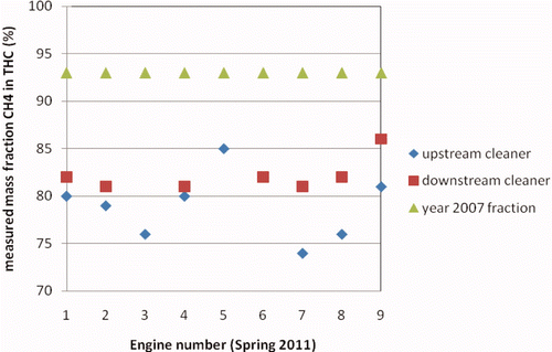
KEMA searched for an explanation for the deviations between the year 2007 fraction of methane and the measured fraction. One explanation might be that in all cases the fuel composition deviated considerably from the standard Groningen composition. Analysis of the fuel gas applied revealed that this was not the case. Closer analyses of the specifications of the FID detector revealed that calibration of such a detector with propane overestimates the concentration of methane by roughly 10%. This is due to different response factors of the FID to ethane and especially to methane compared with propane. Subsequently, the hydrocarbon concentrations as measured with the gas chromatograph were compared with the total HC concentrations as measured with the FID for 16 measurements in 2007. This confirmed that the FID gave on the average 12% higher readings than the combined gas chromatographic HC concentrations. Consequently, with high certainty it can be concluded that the total HC concentrations as reported in 2007 and 2009, and shown in –, are too high. Since methane and not propane is the major constituent of the HC, calibration of the measurement system with methane instead of propane will improve the accuracy. However, in that case an underestimation of the higher HC will occur.
5.2. Further explanation for the variable HC emissions of engine type 8
The level of measured hydrocarbon emissions of engines 8, 9 and 23, all of an identical type, showed a strong dependence upon air-to-fuel ratio during the measurements in 2007 and 2009 (see again ). Engine 8 was measured again in 2011, and the HC emission had increased from 605 mg C/m3 at 3% O2 in 2009 to 1106 mg C/m3 at 3% O2 in 2011 as measured after the catalyst. Any misfiring will be clearly revealed by the power stability measurement. This power stability measurement was not used during HC measurements being carried out before 2011. The power stability measurement showed that the engine was not misfiring during the 2011 test. Therefore, misfiring can be excluded as the cause of the increase in HC emissions. Although the aluminium pistons had been replaced by steel ones, the explanation has to probably be found in the increased O2 percentage. The measured O2 value, i.e. the value not corrected for incomplete combustion, increased from 10.25% in 2009 to 10.56% in 2011. The HC emission of the latest measurement is close to the same as that of the identical engine number 23 in 2009, which was running with almost 10.5% O2 in the exhaust (). With some precaution, it might be concluded that the HC emission of this prechamber engine type is very sensitive to the air-to-fuel ratio. The underlying mechanism is most probably partial combustion in the main combustion chamber. In this case, the crevices are only responsible for part of the hydrocarbon emissions.
5.3. Power stability measurement results
The measurement of the stability of the power output of the cogeneration installations is an integral part of the 2011 measurements. Variations in power output reveal misfiring as well as unstable combustion. Of the 10 engines measured in spring 2011, three engines running on natural gas showed severe misfiring, while four ran quite unstable. Misfiring can be caused by improperly functioning spark plugs and by ignition failure due to very lean mixtures. Unstable running without misfiring can be caused by mixtures which are rather lean and by an incorrect ignition timing. The single engine running on bio gas was running very unstable, due to severe misfiring. Misfiring especially can lead to high emissions of hydrocarbons. Proper maintenance in combination with a stability monitor can help to avoid prolonged misfiring.
6. Conclusions
| • | A general conclusion is that investigations into the emissions of machinery have to be carried out by a team with thorough knowledge in the areas of emission measurement technology and the underlying machinery technology. However, in practice this is often not the case. A simple approach of just registering the output of measurement instruments and reporting these holds a high risk of errors leading to inappropriate conclusions. | ||||
| • | A flame ionisation detector (FID) as used for the hydrocarbon measurements described in the paper has fairly identical response factors for hydrocarbons higher than propane. However, if a FID is used for measuring CH4 but has been calibrated on propane, a substantial overestimation of the hydrocarbon concentrations occurs. | ||||
| • | The now determined actual methane emissions of the tested spark-ignited gas engines, if corrected for an FID error of 10%, roughly lie between 450 and 2100 mg C/m3 at 3% O2. This equals a methane emission range between 125 g/GJ to 600 g/GJ, expressed in gram of CH4 per GJ of lower heating value of the fuel. This emission level ranges between 0.6 and 3% of the fuel input. | ||||
| • | In general, spark-ignited gas engines designed for running in the leaner air–fuel mixture range around lambda 2.0 do not have higher hydrocarbon emissions than engines designed for running at lambda 1.7. | ||||
| • | For an individual spark-ignited gas engine, an increase in lambda from 1.94 to 2.00 has shown to more than double the hydrocarbon emissions. This is most probably due to the fact that pockets of fuel and air escape the combustion process. | ||||
6.1. General remark
The results of the extensive HC emission measurements of gas engines carried out in 2011 on behalf of Ministry I&M and NL Agency will be made available at a later stage. It is expected that the results will provide further insight into possible solutions of abating the HC emissions.
Additional information
Notes on contributors
Michel de Zwart
This paper was presented at the Sixth International Symposium on Non-CO2 Greenhouse Gases, Amsterdam, NL, 2–4 November 2011.Notes
1. According to the First commitment period of Kyoto 2008–2012, the GWP of CH4 is 21. For the second commitment period, this GWP will be adjusted to 23.
2. For commercial reasons, the technical details of the engines cannot be revealed in this report.
References
- Dutch Decree on emission regulation mid-sized combustion plants (BEMS) . 2009 . Staatsblad 547
- de Wit , J and Mofid , i . 2005 . Methane oxidation catalyst for gas engines project report , Hørsholm , , Denmark : Danish Gas Technology Centre .
- Dyer , TM . 1985 . On the sources of unburned hydrocarbon emissions from lean burn engines . Düsseldorf: VDI – Berichte , : 17 – 38 .
- Engelen , PAC. 2009 . Overzichtsrapportage vervolgonderzoek methaanemissies bij gasmotoren op continu vollast -- voorjaar 2009 . KEMA Technical & Operational Services , Arnhem, 3 November 2009
- European Association of Internal Combustion Engine Manufacturers (Euromot) . Reduction of hydrocarbon emissions from stationary gas engines . Euromot NON-Paper, Frankfurt . November 23 2010 .
- Geerssen , M . 1988 . Physical properties of natural gases , Groningen : Nederlandse Gasunie .
- Hicks , R A , Lawes , M , Sheppard , CGW and Woolley , R . The development of spark ignited turbulent flames . Proceedings of the 8th International Symposium on Applications of Laser Techniques to Fluid Mechanics; . July 1996 . Lisbon, Porgugal
- Klimstra , J . Performance of lean-burn natural-gas-fueled engines – on specific fuel consumption, power capacity and emissions . SAE Paper 901495, Future Transportation, Technology Conference and Exposition . Aug 13–16 1990 , San Diego, California .
- Olthuis , H J and Engelen , PAC . 2007 . Overzichtsrapportage emissieonderzoek methaanemissies bij gasmotoren op continu vollast , Arnhem : Kema Technical & Operational Services .
- van der , Maas CWM , Coenen , PWHG , Zijlema , PJ , van den , Berghe G , van den , Born GJ , Brandt , AT , Guis , B , Geilenkirchen , G , Molder , te R and Nijdam , DS . 2010 . “ Greenhouse gas emissions in the Netherlands 1990–2008 ” . In National Inventory Report 2010 Netherlands Environmental Assessment Agency (PBL) , Bilthoven : Kema Technical & Operational Services . April. PBL report 500080017/2010
