Abstract
Manure storage is a source of methane. An option to mitigate methane emissions from manure storage is to collect the methane produced in the storage and feed it into a dispersion layer underground. In the soil above, the methane is subsequently oxidized by methanotrophic bacteria. A previous study indicated that the method seems technically and economically feasible with costs for emission reduction of methane of €1–4 per ton CO2‐eq. mitigated. The concept was demonstrated at a pilot facility next to a storage for manure digestate and proof of concept was achieved at field scale. It was technically simple to capture methane and feed it into a dispersion system at about 1 m below the surface. Indications exist, that part of the methane was oxidised in the soil. However actual methane oxidation could not be determined, because there are serious doubts whether all methane did enter the oxidation field. For actual applications, quantification of gas generation in manure and oxidation rate of the soil need to be improved, to design an oxidation field.
1. Introduction
1.1. Methane emissions from manure storages
Anaerobic degradation of organic material in manure results in the emission of methane. Total Dutch methane emissions from manure management in 2012 were 125 Gg CH4 (RIVM Citation2014), which is 2.6 Tg CO2-equivalents. This boils down to about 1.3% of the total Dutch greenhouse gas emissions of 195 Gg CO2-eq. For the Netherlands, an emission reduction target (excluding Emissions Trading systems) is defined for 2020 of 16% (government.nl Citation2015), compared to 1990-emissions and therefore in 2020 national emissions should be reduced to 180 Gg CO2-eq (RIVM Citation2014). To meet the 2020 emission objective, an additional 10% emission reduction will be required in the next years. So when technology becomes available for manure storages, it might make a significant contribution to this greenhouse gas mitigation objective.
1.2. Biological methane oxidation
Attempts are made to reduce methane emissions in biofilters, specifically for manure storages but also for other sources like landfills and waste treatment facilities (e.g. Melse Citation2003). In such a biofilter, a mixture of methane and air (generally with methane concentrations substantially below the lower explosion limit of about 5 vol%) is forced through the biobed. However, due to the poor solubility of methane in water, conversion is limited to about 0–20% for the residence times that are common in biofiltration (30 s–2 min). Scheutz et al. (Citation2009) give a review of methane oxidation capacities of biofilters and report values in between 50 and 600 g day−1 per m2 biofilter surface. With typical biofilter bed depths of 1–1.5 m, this boils down to 35–600 g m3 day−1.
Methane emissions from landfills are partially removed in the landfills top-layer through oxidation by methanotrophic bacteria which are naturally present in most soils. In this case biogas (containing 55–70 vol% methane) comes from the waste body and oxygen diffuses into the top-layer from ambient air. Methanotrophic activity occurs in a limited zone, where methane and oxygen meet and this is generally located in the upper 30–40 cm of the soil profile (Jones & Nedwell Citation1993; Czepiel et al. Citation1996; Scheutz et al. Citation2004, see also Figure at the end of the article).
In the past decades, there has been an increasing interest in options to improve methane oxidation and engineered top-layers were developed, capable of removing up to 100% of the methane at fluxes of 50–75 g m2 day−1 (e.g. Huber-Humer et al. Citation2008; Scheutz et al. Citation2009). Important conclusion of this research is that many soils can build up considerable methane oxidation capacity. The physical and chemical parameters for an optimized oxidation process are well-documented (Scheutz et al. Citation2009). However, according to Huber-Humer et al. (Citation2008) for an effective methane oxidizing top-layer, a gas dispersion layer is required to enable a homogeneous supply of methane from the bulk of the waste to the top-layer.
1.3. Application at manure storages
What works for landfills, might work for manure storages as well. Oonk and Koopmans (Citation2012) described this option. The main conclusions of this study were the following: methane might be collected at the vents of the storage and fed into a dispersion layer at about 1 m depth in the surrounding soil (see Figure ). When the gas migrates from this dispersion layer through the soil, it is oxidized by methanotrophic bacteria. An annual average methane oxidizing capacity of about 50–75 g m−2 day−1 seems to be feasible in sandy or loamy soils, without major modifications. A single manure storage will require a few 100 m2 of soil to abate 70% or more of its methane. The system seems to be economically feasible and cost-effective. Additional investments are less than 5% of the total costs of a manure storage. Costs for emission reduction were estimated to be €1–4 per Mg CO2-eq.
To evaluate the technical feasibility of the method, a demonstration project was performed at full-scale at a storage of a slurry of manure digestate in Sterksel, The Netherlands. Prior to the demonstration, the soil samples from Sterksel were characterised and ability of the soil to oxidise methane was evaluated on a lab-scale. This lab-scale research is described in Chapter 2. The demonstration project itself is described and discussed in the Chapters 3 and 4.
2. Characterisation and evaluation of methanotrophic activity of soil samples from Sterksel
2.1. Soil characterisation and methane oxidation potential
The methane oxidizing capacity of soils depends on their chemical and physical properties that frame the living conditions of the methanotrophic bacteria as well as on the time and intensity of exposition to methane. The activity of the established bacterial community depends largely on the soil temperature and the soil gas exchange with the atmosphere. Several studies address the optima of soil material and ambient conditions for methane oxidation (Gebert et al. Citation2003; Scheutz et al. Citation2009; Gebert, Streese-Kleeberg, et al. Citation2011; Röwer et al. Citation2011). Good results can be expected from soils with pH values between 5.5 and 8.5, organic content between 2 and 4%, a salinity below 4 mS cm−1 and an air capacity of least 14%. This makes especially sandy soil suitable for methane oxidation. The high air capacity is especially important to make sure that the bacteria are supplied with the substrates methane and oxygen and that the resulting carbon dioxide is purged. With a lower air capacity the risk is high that pore continuity and hence soil aeration is interrupted in periods of rainfall.
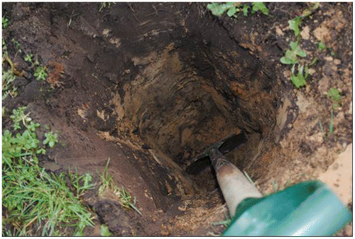
In an excavation at the projected site for the pilot a two layer soil profile was found (Figure ). The sandy material contained organic material in the topsoil (30–40 cm) while the subsoil horizon was of a yellow color with some spots of oxidized iron indicating temporal influence of water. For evaluation of biological and physical properties topsoil, subsoil and a mixture of both materials were analyzed by Universität Hamburg (Table ).
Table 1. Soil chemical and physical properties of the soil in Sterksel.
A batch incubation test was performed to test the methane oxidizing capacity of the materials. Triplicates of about 14 g DM soil material were incubated in 100 ml bottles. The water content of the soil material was adjusted to 60% of its maximum water retention capacity which was 19.6, 15.4 and 12.2% w/wDM for topsoil, mixture and subsoil respectively. Methane was added to 10% CH4 in air and incubation took place at 20 °C in the dark. These conditions were chosen because the expected conditions in the biofilter are high CH4 concentrations and elevated temperatures due to the influx of gas from the storage bag. The headspace concentration in the bottles was measured over a time period of three month on a weekly basis by gas chromatography. If CH4 concentration was depleted to 1% fresh CH4 was added. The depletion rate was determined after several cycles of feeding methane and its oxidation. This was done to develop the maximum oxidation capacity as it would be in a material with a prolonged exposition and thus well-developed bacterial community. The topsoil performed best showing a methane oxidation capacity of 18.4 μg h−1 g DM-1. The subsoil performed poor with only 0.92 μg h−1 g DM-1. The mixture was 30% less performant than the topsoil but still showed a reasonable methane oxidation rate of 12.4 μg h−1 g DM-1. An overview of batch studies on methane oxidation rates of landfill cover soils is provided in Scheutz et al. (Citation2009). The rates found in this study are within the range of the cited studies.
2.2. Characterisation of methane potential of manure and manure digestate
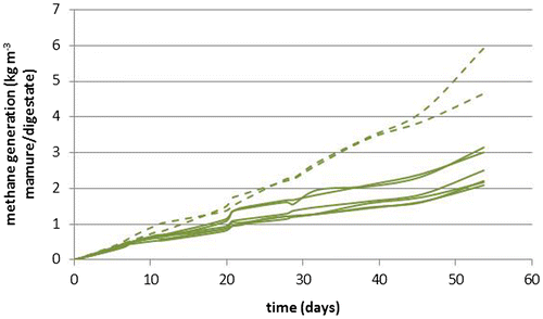
Prior to anaerobic digestion, the methane potential is increased by adding solid residues. However upon anaerobic digestion, large part of the methane potential is removed again. Prior to design of the oxidation field, composition and methane generation capacity at room temperature of both the unfermented pig manure and digestate from Sterksel was assessed at University Hamburg. The results are presented in Figure and Table .
Table 2. Composition of digestate and fresh manure samples.
2.3. Column experiment
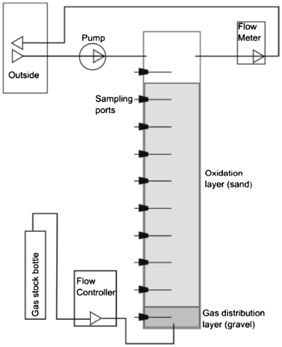
In the full-scale demonstration (see Chapter 3), the mixture of topsoil and subsoil was used. The methanotrophic activity of this mixed soil material was verified by Universität Hamburg on a column scale and using the soil samples, characterised in 2.1. PVC-columns were used, with a diameter of 18.8 cm (for a schematic see Figure ), with artificial biogas fed in from the bottom and ventilated headspaces flushed continuously with ambient air. The base area of the columns was 278 cm2. In the bottom about 4 kg of gravel was used as gas distribution layer (GDL) which was about 10 cm thick. On top of the GDL, 34.5 kg of the mixed soil was filled to a height of 90 cm, yielding a bulk density of 1.4 g DM/cm3. The soil material was built into the column in consecutive layers of 10 cm each to get a homogeneous compaction. The water content of the material was 11.1% w/w (7.9% v/v).
The gas used was an artificial landfill gas containing 60% CH4 and 40% CO2. Gas supply was realized through a single inlet point located at the center of the base of the GDL, using mass flow controllers (MFC 0–20 ml/min, Analyst-MTC Messtechnik GmbH). Each column was supplied with its own controller. The headspace was flushed with ambient air, supplied from outside the building and controlled using flow-meters (0–500 ml/min, Analyt-MTC Messtechnik GmbH). Measurement of the gas composition in the column headspace and the soil gas phase was performed by gas chromatography.
Air capacity of the soil material at the targeted bulk density was estimated according to Bodenkundliche Kartieranleitung 5 (Ad-hoc-AG Boden Citation2005) (German Soil Classification). According to it the material has an air capacity of 34% v/v and a field capacity of 16% v/v. Subtracting the 7.9% v/v water content from the total porosity of 50% v/v an air filled porosity of 42.1% could be assumed.
The columns were operated from September 2012 to June 2013 at room temperature (18–22 °C) and at different methane loads. Column A was initially set to 33 g CH4 m−2 day−1, 5 October 2012 decreased to 30 g CH4 m−2 day−1 and 21 November increased to 67 g CH4 m−2 day−1. Column B was initially set to 33 g CH4 m−2 day−1, 5 October 2012 decreased to 30 g CH4 m−2 day−1 and 30 April 2013 increased to 117 g CH4 m−2 day−1.
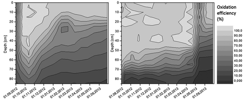
Oxidation efficiencies were calculated at various depths, using the CO2–CH4 ratio approach proposed by Gebert, Röwer, et al. Citation2011. The gas profiles at different loads are displayed in Figure . It can be seen that an increase of the CH4 load reduces the depth of aeration and results in a rise of methane closer toward the surface.
Figure 5. Gas profiles of column A and column B at a load of 30 g CH4 m−2 day−1 (1.76 l CH4 m−2 h−1, column A and B-left), 67 g CH4 m−2 day−1 (3,9 l CH4 m−2 h−1,column A-right) and 117 g CH4 m−2 day−1 (6.83 l CH4 m−2 h−1,column B-right).
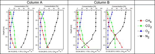
The columns were able to oxidize the entire load nearly the whole time (Figure ). After the increase of the load from 30 g CH4 m−2 day−1 to 117 g CH4 m−2 day−1 column B took around six weeks to recover efficiencies close to 100% (column B, May–July 2013).
3. Materials and methods in the full-scale demonstration
3.1. Design and construction of the pilot
November 2011 the pilot was constructed next to a storage bag of VIC in Sterksel. VIC Sterksel is part of Wageningen University and is a research farm for innovative and sustainable pig husbandry (VIC stands for Swine Innovation Centre). The storage bag has a maximum capacity of 1000 m3 and is used as a temporary storage for digestate from an anaerobic digester. Temporary means that digestate is supplied to the storage bag and removed again, whenever a customer wants part of the manure. In practice this means that the volume of digestate stored in the bag varies almost on a monthly basis between 100 and 900 m3.
The bag is filled with digestate, which is a pig-manure, treated in an anaerobic digester, together with some additional solid residues from agriculture of feedings industry (co-digestion).
In the feasibility study (Oonk & Koopmans Citation2012), a first order decay model is described for methane generation in manure storages. Model parameters are chosen in such a way, that on an annual basis, the results are in agreement with the Dutch national estimate for this source (Van der Hoek & van Schijndel Citation2006). Methane generation is calculated as:
Where α is methane production in kg per day, (OM × B) is the product of the actual organic matter in the manure (OM) and the actual methane potential of the organic matter (B) and k is the rate constant of biodegradation. Initial values for OM and B are assumed to be equal to the values used by Van der Hoek and van Schijndel (Citation2006): an OM0 for swine manure of 60 kg/ton and a B0, of 0.24 kg CH4/kg OM). The value for k is chosen in such a way, that the fraction of OM × B that is converted to methane corresponds to the value assumed by Hoeks and van Schijndel (Citation2006): This results in values for k of 0.0061 day−1 in summer and 0.0031 day−1 in winter. The lab-scale fermentation tests indicated that methane generation from digestate is about 50% of the methane generation from manure (see Figure ), so for design of the methane generation at Sterksel it was assumed, that methane generation is 50% of the modelled generation for swine manure. Therefore the product of OM × B0 is assumed to be 7.1 kg CH4 ton−1 digestate. Using this model, methane generation from the Sterksel storage is at maximum (bag completely filled with fresh digestate in summer) about 40 kg CH4 day−1. In winter periods, the maximum is about 20 kg CH4 day−1. This modelled methane generation, based on the assumptions by Hoeks and van Schijndel (Citation2006), is in good agreement with the methane generation in the lab as shown in Figure . In the lab, methane generation from digestate was about 2.5 kg/m3 manure in 50 days. Extrapolated to a manure bag filled with 1000 m3, this boils down to 50 kg of methane per day.
In Oonk and Koopmans (Citation2012) and based on Huber-Humer et al. (Citation2008), the oxidation capacity of the soil is assumed to be 50–75 g CH4 m−2 day−1 as an annual average, and in summer most likely higher. Together with the estimated methane generation as described above, this would result in an oxidation field of about 500 m2. However both the estimate of methane generation and methane oxidation were considered uncertain. To avoid the risk of having insufficient methane to explore the soil oxidising capacity around its maximum value (e.g. if methane generation were less and methane oxidation were much higher than expected), the size of the oxidation field was chosen to be much smaller: 100 m2.
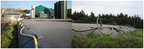
The 100 m2 field was subdivided into three sections with different gas distribution systems each. For connecting the storage bag with the oxidation field the four vents of the manure bag were connected to a 6.5 cm diameter flexible hose, using standard PVC-fittings (see Figure ).
The flexible hose was connected to the three test fields. In order to keep pressure drop over the system to a minimum, no valves were installed to control the distribution of biogas over the fields. Each test-field measured 5 × 7 meters, yielding a total surface of slightly over 100 m2. The fields were sealed from each other and from the surrounding area, using 2 m HDPE-foil. The three test-fields differed in the way biogas is dispersed at the bottom of the methane oxidising soil (see also Figure ):
| • | In field 1, the drainage hoses (also 1 m apart and at 1 m depth) were installed to a depth of 1 m with a distance of 1 m of each other and they were covered by a 25 cm layer of composted wood chips. | ||||
| • | In its most simple form (field 2), biogas was distributed using a system of drainage hoses at about 1 m depth and located 1 m apart from each other at the bottom of the field. | ||||
| • | In field 3, the drainage hoses (1 m apart and at 1 m depth) were located in a layer of wood-pellets and subsequently covered with separation cloth. | ||||
Figure 8. Construction of the 3 test fields. From left to right: deposition of wood-chips on the drainage tubes; drainage tubes at the base of the oxidation bed; separation cloth between pellets and soil; covering the drainage tubes with pellets.
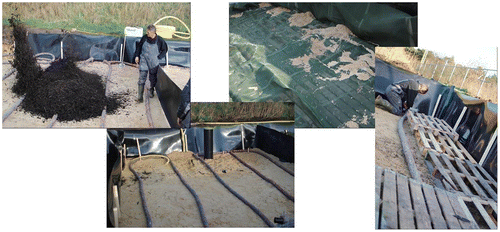
The excavated soil was mixed and subsequently put back in place and during winter 2011, the field was allowed to settle. About 25% of the original soil did not fit anymore, due to the space occupied by the dispersion system and due to reduced compression of the sand itself.
About 1 m2 of the surface below oxidation field 2 was covered with HDPE-liner, which collects part of the precipitation as it leaches from the bottom part of the oxidation field into the subsoil. This water is collected in a well, from which it can be sampled.
In May 2012 the surface was levelled and seeded with grass. In July 2012, after development of the grass vegetation cover, monitoring of methane oxidation commenced.
3.2. Measurements and its results
3.2.1. General approach
Quantification of methane generation and methane oxidation was done by measuring the amount of methane fed into the system and the methane emissions from the field.
Valid measurements could only be performed, when conditions were stable. E.g. after removal of significant part (>100 m3) of digestate from the storage, it took at least a day (most likely more) before internal biogas pressure was restored and supply of methane to the oxidation fields was back to normal level. Also upon smaller or larger repairs of the system (e.g. after removing water from a hose), internal pressure in the bag was disturbed. Stable atmospheric conditions was another criterion for valid emission measurements. For landfills it is known, that e.g. rainfall affects the permeability of the top-soil and reduces methane emissions temporarily. Also a significant rise or drop in barometric pressure has effect on methane emissions. In order to minimise these influences emission measurements were performed when stable, preferably dry atmospheric conditions prevailed for three consecutive days. No emission measurements were performed for three days after disturbing events.
The ambition was to perform monthly measurements. However due to the requirements mentioned above, no valid measurements were performed in August 2012 and May/June 2013. In September 2012, box measurements had to be cut-off due to sudden rain-fall.
3.2.2. Methane generation in the digestate
The total amount of biogas fed into the three test-fields and their temperatures were measured, using a handheld thermal anemometer (Testo 425). After it was observed that biogas production was much higher than expected, values were validated using a 2nd anemometer (a Testo 405-V1). The Testo 425 measured gas speed and temperature at sections of PVC-tube with a known diameter (28.4 mm ID PVC-tube), which allows calculation of the total volume-flow and the volume-flow into the three test-fields. Methane concentrations in the biogas was measured using a Gazomat TDL-500 Inspectra Laser which is a non-destructive laser adsorption measurement. Its measurement ranges are 0–1000 ppm and 0–100% gas volume. Its typical accuracy is 1 ppm.
3.2.3. Methane emissions from the test-field
Methane emissions were monitored with two methods. First emission detection from the field was done qualitatively by screening methane concentrations just above (<5 cm) the surface and marking locations with elevated methane concentrations (>100 ppm) with a peg. Subsequently static box-measurements were performed on every 2nd m2 and in addition on every m2, where a hotspot was found. This is illustrated further near the discussion of the measurement results in Figure .
For methane screening the TDL-500 unit was used with a sampling rod. Static box measurements were performed using a box with 0.25 m2 surface area and a volume of 70 l. The box was fitted with a small propeller fan to enhance mixing in the box. Development of methane concentration in the box was analysed with the TDL-500 with a sample rate of 30 l of air min−1. The exhaust air from the analyser was fed back into the box. The sampling frequency and time of enclosure depended on the observed increase of concentrations in time. At high emissions, concentrations were recorded every 10 s and the measurement was cut off, when increase in concentrations ceased to be linear. At non-hot spots concentrations were recorded every 30 s. Typically a measurement lasted 1–5 min.
From the increase of the concentration over time measured in the box a flux from the surface under the box is calculated. The result is the methane emission (in g day−1) for the surface below the box. This flux is assumed to be representative for the m2, where the measurement was performed. When a single m2 had one or more hotspots, the static box-measurement was performed at the position where the highest methane concentrations were observed. The footprint of a box-measurement is only 0.25 m2. The assumption that the measured flux from the 0.25 m2 is representative for the entire m2 results in an overestimation of the flux from this m2. Fluxes from the m2s where no box-measurement was done were estimated by interpolation of measurement results next to it, excluding the measurements at hot-spots.
3.2.4. NH3, H2S in the biogas and composition leachate in the collection well
Concentrations of NH3 and H2S in the biogas were measured, using analytical tubes (Uniphos, NH3: 10–300 ppm; Uniphos H2S: 100–2000 ppm). NH3-concentrations varied between 60–80 ppm; H2S-concentrations were about 100–130 ppm.
The monitoring well was emptied at the end of June 2012, sampled in June 2013, with the sample being sent to the lab for analysis. Ammonia was 12.5 mg/l, nitrate 0.28 mg/l, while nitrite was not detectable. Sulphate concentration was 658 mg/l.
4. Results and discussion
4.1. Operational experiences
Capture of methane from the digestate storage and subsequently injection into the dispersion layer below the ground could be realized without technical difficulties. The system was in operation for 1 ½ years without real flaws. However the system does require some attention (~15 min of work every 2 weeks) to overcome small difficulties, as removal of condensing water from the hoses or repair a hose when it got stuck underneath the bag, when the bag is filled again.
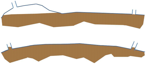
When the manure bag is filled beyond ~90%, the vents are shut off by the digestate and methane capture is seriously reduced (see Figure ). In future applications, this situation might be prevented by adding an extra vent at the highest point in the bag.
Figure 9. The storage bag, ~75% filled with manure and completely filled up (below). When not completely filled, a gas filled headspace is created below one of more vents. Methane can migrate into this headspace and can escape the storage through the flexible hose. When completely filled, vents are locked and methane collection from the vents is hindered.
The pressure drop over the system is limited to about 1 cm water column (100 Pa), which is a reassuring low value and does not pose a threat to the structural integrity of the storage bag.
4.2. Methane supply to the test-fields
The amount of methane, supplied to the test-fields (product of amount of biogas and methane concentration in the biogas) is shown in Table , along with the degree to which the storage bag was filled, the temperature of the biogas (near the point where biogas was fed into the dispersion layer) and day-average ambient temperature.
Table 3. Measured methane generation, gas temperature before injection in the dispersion layer and day-average ambient temperature (as measured at KNMI weather station Eindhoven).
The expected methane generation was at maximum 40 kg CH4 day−1 in summer and 20 kg CH4 day−1 in winter, were the manure bag was completely filled with fresh manure (see Chapter 3.1). In reality in winter methane generation varied from 20 to 70 kg CH4 day−1, depending on the amount of digestate in the bag. In summer methane generation as high as 180 kg CH4 day−1 was measured.
The reasons for elevated methane generation are unclear. A possible reason might be the temperature in the storage bag. Methanogenesis is known to be strongly influenced by temperature (e.g. Donoso-Bravo et al. Citation2009). In the model calculation, the temperature in the bag is assumed to be ambient temperature. At Sterksel temperature was measured, just before the methane was fed into the distribution layer, so 15–35 meters away from the vents. Even at that location, the temperature of the biogas from the bag was increased, compared to ambient (see Table , measured temperatures in the biogas are compared to average temperatures that day, as measured by the nearby KNMI-weather station Eindhoven). This might have several reasons: (i) digestate is pumped into the storage bag at 37 °C; (ii) methane generation itself might be slightly exothermic, so the process might speed itself to some extent and (iii) the storage bag itself is to some extent designed as a solar water heater: it has a large and black surface (~400 m2) and limited depth (~2.5 m).
4.3. Methane emissions from the field and oxidation
Methane emissions from the test-fields were measured at the same days as methane supply to the test-fields (see Table ). At a number of occasions, the methane supply to the oxidation fields was relative low: about 20–35 kg day−1 (see Table ) and little or no methane was measured above the oxidation field. In September 2012 methane supply was very high. During surface screening numerous hot spots were observed, especially in test fields 2 and 3. However box-measurements of methane emissions were hindered by sudden rainfall.
In November 2011, early December and March 2012, methane supply was about 50–60 kg day−1 of and enhanced methane concentrations were detected, at several locations, just above the field. The results of the static box-measurements in November 2012 are shown in Figure . Methane mainly escapes from the borders of the test-fields. Field 1 only has significant source of methane (on the m2, indicated as A1 in Figure ); field B mainly had methane emissions at the m2s indicated by A6-A10. Field C mainly had emissions on the m2s, indicated as A15–G15. Large parts of the test-fields did not show any emissions. In December 2012 and March 2013 the location of emissions was about the same as in November 2011. The only exception was the emission from Cell G15, which grew out to the main hotspot in this period (0ver 3,600 g methane day−1).
Figure 10. Methane emissions from the test-fields on 17 November 2012 (in g CH4 per day). Every cell represents a m2 of the oxidation field. The emissions in black are actually measured by flux-box measurements. The values in grey are obtained by interpolation of measured emissions from the neighbouring cells without hotspots.
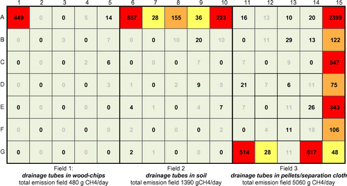
The hotspot in Cell G15 seems to be increased by rainfall, that flushed part of the soil along the HDPE-liner to the open space below the pellets, creating a short-cut for gas to escape. The increase of this hotspot seems to the the reason for the reduction in methane conversion in field 3. After some times, hot-spots were easily recognised, because of local vegetation damages (see Figure ). Based on measurements with the anemometer, the field with the wood-pellet-based distribution system (field 3) received roughly about 60% of all methane. The remaining 40% was about evenly distributed over field 1 and 2. Table gives an overview of methane supplied to the fields and methane emission measured.
Figure 11. Vegetation on and next to test-field 1 (Cells G1–G5 in Figure on 29 April, 2013). The perimeter of the test-field is indicated by the yellow line.
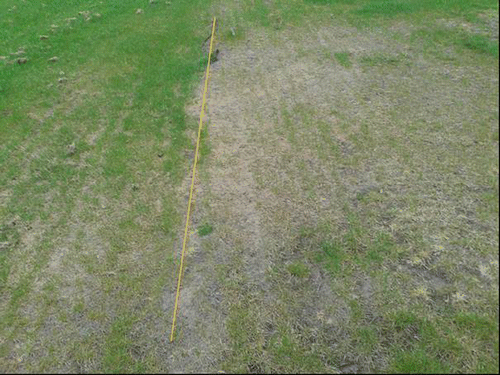
Table 4. Methane supply and emissions from the test-fields.
Measurements were performed under stable and dry conditions, and this might have had impact on methane emissions. For example, in rainy periods the soil will be more saturated, gas porosity and oxygen diffusion might be reduced and as a result methane oxidation might be reduced as well. So even though measurements were performed in all seasons, measurements cannot be considered to be a complete basis to assess annual average oxidation.During all emission measurements, methane emissions were low, compared to the amount of methane that was supplied to the field. This suggests a high degree of methane conversion for all three fields at all times. E.g. in November 2012 measurements suggest methane oxidation of 96% for field 1 and almost 90% for fields 2 and 3. When this all would be attributed to methane oxidation, methane removal would be 350 to 1000 g CH4 m−2 day−1. In comparison with methane oxidation rates described elsewhere (~15–85 g CH4 m−2 day−1 in real applications; to 150–250 g CH4 m−2 day−1 in the lab, see Scheutz et al. Citation2009) this is high.
In this system, biogas from the storage bag (containing ~62.5% of methane) comes from below, while oxygen required for methane oxidation enters the oxidation layer from the atmosphere by diffusion (see Figure ). The oxidation rate is limited by both the intrinsic methanotrophic activity of the top-layer (the methane oxidation rate in case of unlimited oxygen supply, e.g. as indicated by the batch incubation test in paragraph 2.1) and the rate of diffusion of oxygen into the top-layer (e.g. Scheutz et al. Citation2009).
Figure 12. Methane oxidation in oxidation field. Biogas is fed into a dispersion layer at about 1 m depth. Oxygen enters the oxidation field from ambient air by diffusion. Somewhere in the soil (most methane is assumed to be oxidised in the upper 30–40 cm) methane and oxygen meet, allowing methane oxidation.
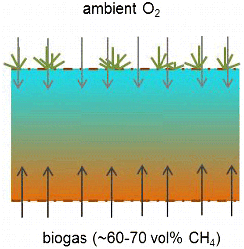
In the column test the situation as described in Figure is simulated. Almost complete methane oxidation was obtained at a methane load of 117 g m−2 day−1. Oxygen diffusivity in soils depends on the soil porosity (Møldrup et al. Citation2000, Citation2001; Gebert, Gröngröft, et al. Citation2011). The porosity of the soil mixture in Sterksel was high with 34% air filled porosity with moisture at field capacity. Gebert, Huber-Humer, et al. (Citation2011) suggest oxygen diffusion should allow an oxidation rate of 100 g m−2 day−1 at 30% porosity. So for the test-field, an oxidation of about 100–120 g CH4 m−2 day−1 is conceivable.
However values of 350–1000 g m−2 day−1 are unlikely because of the limitations in oxygen diffusion. As a result, there are serious doubts whether all methane that was fed into the distribution layers, actually did migrate through the top-soil and was oxidised there. Possibly, part of the methane did migrate sideways, underneath the HDPE-liner at the sides of the oxidation field and away from the test-fields.
There are strong indications, that substantial part of the methane did enter the oxidation bed. And since little methane subsequently came out, most methane that entered the oxidation bed was oxidised there. Indications that part of the methane did enter the test-field are:
| • | In the test-fields, development of vegetation was lagging behind, compared to vegetation immediately around the field (both sown with the same type of grass and at the same time). This is an indication of reduced oxygen concentration around the grass-roots, most likely caused by biogas migrating from below; | ||||
| • | Occasionally methane concentrations were measured in the soil at about 30 cm depth. At this depth, concentrations of 10–30% methane were measured. So methane does migrate into the oxidation bed. On a lab-scale it is demonstrated, that the soil has considerable methanotrophic activity, so once methane migrates into the soil, methane oxidation will occur to some extent; | ||||
| • | An indication of the amount of biogas, that actually entered the oxidation field might be obtained from the sulphur mass balance. This mass balance is based on only few measurements and there was also no control measurement of sulphate in a nearby collection well in undisturbed soil. However the water, percolating through the oxidation bed, contains a considerable amount of sulphate (over 650 mg/l, see paragraph 3.3.4). Sulphate concentrations, commonly found in ground water in sandy soils, influenced by agriculture are on average about 50 mg l−1, with 99% of all values below 350 mg l−1 (Fraters & De Goffau Citation2014). So the sulphate concentration in the water, coming from the field seems to be increased. A likely source of sulphate is H2S in the biogas, oxidised to sulphate in the oxidation bed. A simple mass balance calculation indicates that the amount of biogas seems to be substantial. Excess rainfall from July 2012 to June 2013 can be estimated to be 360 mm.Footnote1 When it is assumed, that the oxidation bed increases the sulphate concentration in the water by 300–600 mg l−1 (650 mg sulphate per l−1 in the control well minus 50–350 mg l−1 in the natural situation: 50 mg l−1 is the average concentration; 350 mg l−1 is the 99%-percentile concentration of sulphate in ground water in sandy soils, influenced by agriculture), 36–72 g S per m−2 y−1 was flushed out. With about 130 ppm H2S (200 mg S per m−3) biogas, about 180–360 m3 y−1 of biogas (~85–170 kg CH4 m−2 y−1) is required per year per m2 surface, to explain the amount of S being flushed out. | ||||
5. Conclusions
In conclusion, the demonstration of methane oxidation at the manure digestate storage in Sterksel was a moderate success. Proof of concept was achieved. It was demonstrated that it is technically easy to capture methane from a storage bag and feed it into a dispersion system at about 1 m below the surface. Strong indications exist that a substantial amount of the methane is actually oxidised in the soil. The system itself can be as easy as the setup described the feasibility study (Oonk & Koopmans Citation2012) and applied in this study. This also means that investment costs, as specified in the feasibility study are still valid. However, the system continues to requires some maintenance attention (at maximum ~15 min per 2 weeks) to run properly.
Methane generation in the storage was higher as expected. Actual methane oxidation could not be determined, because there are serious doubts whether all methane did enter the oxidation field. As a consequence, the main challenge for future is to quantify the required size of the oxidation field. Refined models for methane generation in a manure storage and methane supply to the oxidation field and improved methods to predict the oxidation efficiency of the oxidation field are required for the sizing of future projects.
Acknowledgements
This demonstration was funded by the Small Business Innovation Research (SBIR) program on the reduction of methane emission from manure storages, executed by the Reduction programme for non CO2 greenhouse gases (ROB) from NL Agency and the Ministry of Infrastructure and Environment.
Disclosure statement
No potential conflict of interest was reported by the author.
Notes
1. In the period July 2012 to June 2013 precipitation was 760 mm and Makkinks reference evaporation 560 mm. The vegetation on the test-fields was grass, which was not intensively mowed, so a crop factor of about 0.7 might be applied, leaving a real evaporation of 400 mm and excess rainfall of 360 mm per year.
References
- Ad-hoc-AG Boden. 2005. Bodenkundliche Kartieranleitung [Soil mapping instructions]. Mit 103 Tabellen und 31 Listen. 5. Aufl. Stuttgart: Schweizerbart.
- Czepiel PM, Mosher B, Crill PM, Harriss RC. 1996. Quantifying the effect of oxidation on landfill methane emissions. J Geophys Res. 101:16721–16729.10.1029/96JD00222
- Donoso-Bravo A, Retamal C, Carballa M, Ruiz-Filippi G, Chamy R. 2009. Influence of temperature on the hydrolysis, acidogenesis and methanogenesis in mesophilic anaerobic digestion: parameter identification and modeling application. Water Sci Technol. 60:9–17.
- Fraters B, De Goffau A. 2014. Sulfaat in grondwater en oppervlaktewater in Nederland Overzicht van meetresultaten van nationale meetnetten (In Dutch: Sulphate in ground and surface water. Overview of measurement results of Dutch measurement network). Bilthoven: RIVM Briefrapport 2014-0120, RIVM.
- Gebert J, Groengroeft A, Miehlich G. 2003. Kinetics of microbial landfill methane oxidation in biofilters. Waste Manage. 23:609–619. doi:10.1016/s0956-053X(03)00105-3.
- Gebert J, Streese-Kleeberg J, Melchior S. 2011. Technische Lösungen zur mikrobiellen Oxidation von Methan [Technical solutions for microbial oxidation of methane]. In: Müll-Handbuch ( 4383, Lieferung 1/2011). Berlin: E. Schmidt Verlag.
- Gebert J, Röwer IU, Scharff H, Roncato CDL, Cabral AR. 2011. Can soil gas profiles be used to assess microbial CH4 oxidation in landfill covers? Waste Manage. 31:987–994. doi:10.1016/j.wasman.2010.10.008.
- Gebert J, Gröngröft A, Pfeiffer E-M. 2011. Relevance of soil physical properties for the microbial oxidation of methane in landfill covers. Soil Biol Biochem. 43:1759–1767. doi:10.1016/j.soilbio.2010.07.004.
- Gebert J, Huber-Humer M, Oonk H, Scharff H. 2011. Methane oxidation tool: an approach to estimate methane oxidation on landfills, explanatory note. Assendelft: Afvalzorg.
- Government.nl. 2015. Available from: http://www.government.nl/issues/climate-change/eu-policy.
- Huber-Humer M, Amann A, Bogolte T, Dos Santos M, Hagenauer I, Pauliny W, Reichenauer T, Watzinger A, Wimmer B. 2008. Technischer Leitfaden Methanoxidationsschichten Erstellt im Rahmen der ÖVA-Arbeitsgruppe “Leitfaden Methanoxidationsschichten” [Technical guidelines for methane oxidation layers, established by the Austrian Association for Closed Waste Deposits (ÖVA) taskforce on methane oxidation]”. Vienna: ÖVA.
- IPCC. 2006. 2006 IPCC Guidelines for National Greenhouse Gas Inventories, volume 5, chapter 11, table 11.1, Available from: http://www.ipcc-nggip.iges.or.jp/public/2006gl/.
- Jones HA, Nedwell DB. 1993. Methane emission and methane oxidation in landfill cover soil. FEMS Microbiol Lett. 102:185–195.10.1111/fml.1993.102.issue-3-4
- Melse R. 2003. Biologisch filter voor verwijdering van methaan uit lucht van stallen en mestopslagen [Biological filter for removal of methane from stables and manure storages exhaust air]. Wageningen: Agrotechnology and Food Innovations B.V. ISBN 9054062401.
- Møldrup P, Olesen T, Schjønning P, Yamaguchi T, Rolston DE. 2000. Predicting the gas diffusion coefficient in undisturbed soil from soil water characteristics. Soil Sci Soc Am J. 64:1588–1594.10.2136/sssaj2000.6451588x
- Møldrup P, Olesen T, Komatsu T, Schjønning P, Rolston DE. 2001. Tortuosity, diffusivity, and permeability in the soil liquid and gaseous phases. Soil Sci Soc Am J. 65:613–623.10.2136/sssaj2001.653613x
- Oonk H, Koopmans J. 2012. Oxidation of methane from manure storages in soils. J Integr Environ Sci. Volume 9, Suppl:1, Nov 1, 2012, 225–233.
- RIVM. 2014. Greenhouse gas emissions in The Netherlands 1990–2012, National Inventory Report 2014. Bilthoven (The Netherlands): RIVM.
- Röwer IU, Geck C, Gebert J, Pfeiffer EM. 2011. Spatial variability of soil gas concentration and methane oxidation capacity in landfill covers. Waste Manage. 31:926–934. doi:10.1016/j.wasman.2010.09.013.
- Scheutz C, Mosbæk H, Kjeldsen P. 2004. Attenuation of methane and volatile organic compounds in landfill soil covers. J Environ. Qual. 33:61–71.10.2134/jeq2004.6100
- Scheutz C, Kjeldsen P, Bogner JE, Visscher A de, Gebert J. Hilger HA. 2009. Microbial methane oxidation processes and technologies for mitigation of landfill gas emissions. Waste Manage Res. 27:409–455. doi:10.1177/0734242x09339325.
- Van der Hoek KW, van Schijndel MW. 2006. Methane and nitrous oxide emissions from animal manure management, 1990–2003. Background document on the calculation method for the Dutch National Inventory Report. RIVM report 680125002/2006. Bilthoven: RIVM.


