Abstract
This paper presents a desalination process powered by a microgrid. Desalination is critically important for many countries demanding potable water beyond that available in nature. The desalination process requires a stable power supply system. As the stable power supply system, microgrid, which is a distributed small capacity power system integrating renewable energy with energy storage, has become important. In this paper, small capacity desalination plant powered by a microgrid is implemented and its features are described. The desalination plant is operated by electricity provided from either renewable energy resource such as solar cell or power grid. Overall control of the desalination plant is carried out by a programmable logic controller and status of water production is monitored by energy management system. The implemented desalination plant consumes 5 kW and produces 1 m3/h of fresh water.
1. Introduction
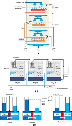
Currently, the most widely employed desalination technologies are multi-stage flash distillation (MSFD) [Citation1], multi-effect distillation (MED) [Citation2], and reverse osmosis (RO) [Citation3]. While MED and MSFD utilize thermal energy, RO uses the mechanical pressure of a pump. Fig. (a) shows the MED method where fresh water is obtained through heat exchange between hot steam within a pipe and seawater sprayed over the pipe. In the 1st Effect, the sprayed seawater evaporates to become vapor due to the heat of the steam pipe. This high-temperature vapor then evaporates more seawater in the 2nd Effect and is eventually expelled as fresh water after losing heat. This process occurs continuously without need for additional heat provision aside from the initial heat supplied by the boiler, and thus the process can conserve energy to some extent. Fig. (b) shows the MSFD method where fresh water is produced using the flashing phenomenon, which instantaneously creates vapor as soon as inputting heated seawater into a low pressure vessel. The flashing vapor produced at this point preheats the seawater flowing in the condenser before reaching the heater, and then the flashing vapor is released as fresh water after undergoing condensation. This process has the advantage of being applicable to mass production as the vaporization–condensation process takes place sequentially over numerous stages.
Fig. (c) shows RO-based desalination process. When a semipermeable membrane is placed between a low-concentration solution and a high-concentration solution of equal amount, liquid initially moves to the high-concentration side, increasing the solution amount; however, the amount of the solution on the high-concentration side does not increase and reach the state of equilibrium over time. This phenomenon is called osmosis and the water head difference between the high-concentration solution and low-concentration solution at equilibrium is the osmotic pressure. The osmotic pressure ∇π is obtained through the following equation [Citation4].(1)
where TDSHigh concentration is total dissolved solid (mg/L) of high-concentration side and TDSLow concentration is total dissolved solid of low-concentration side. When a pressure greater than the osmotic pressure is applied to the high-concentration solution at an equilibrium state, the solvent or water of the high-concentration solution passes through the membrane to the low-concentration solution side, while the solute is not able to pass through the membrane: this process is called RO. Fig. (c) shows a simplified schematic of the RO method. The RO method utilizes the mechanical pressure of a pump.
When desalination plants are constructed at the same location, the typical capital investment costs necessary for the conventional heat-evaporation methods MSFD and MED are around US$1,700/m3. In contrast, the typical capital investment cost for the RO method is reported to be approximately 25% lower [Citation5]. The operating expenses for MSFD and MED are relatively higher due to the greater usage of energy. The operating expense for the seawater RO (SWRO) method is approximately 15% lower than for MSFD and MED [Citation6,7]. The energy cost is the most important element and consequently energy cost becomes the basis for selecting a method.
The RO method is especially economic when treating brackish water. In contrast to the evaporation method requiring a certain amount of energy (cost) regardless of the salinity of the seawater, for the RO method, lower salinity of the raw water means lower osmotic pressure and accordingly the pressure applied by the pump can be lowered to increase the energy efficiency. Initially, a significant amount of energy was consumed due to inexperience in handling the pretreatment process and the high cost of the membrane; however, the energy efficiency has significantly improved with advancements in the pretreatment techniques and lower membrane cost. The problem of treating brine with increased salinity compared to raw water is an important issue that should be considered along with the desalination technology for all three methods. Currently, new technologies are being developed in addition to the aforementioned three methods, such as forward osmosis [Citation8] and the method of obtaining fresh water by separating the salt from gas hydrate crystals [Citation9].
In this paper, RO-based desalination process powered by a microgrid is discussed. Recent study on smart water grid [Citation10] deals with next-generation water management scheme. This work involves new water generation scheme based on microgrid. It is practically implemented for target production of 1 m3/h with 5 kW maximum power consumption. In Section 2, the major considerations for renewable energy resources and energy management system for supplying power to the desalination plant are described. In Section 3, the desalination plant practically implemented is explained. In Section 4, a cost-effective production to optimize the desalination operation by the monitoring system is briefly presented. Finally, conclusion is in Section 5.
2. Microgird for desalination process
2.1. Energy management system
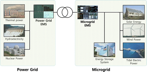
Fig. shows a microgrid system integrated with power grid [Citation11,12]. The range of power scale of the single plant-level microgrid is 1 kW–2 MW. The microgrid can be categorized into grid-connected type and stand-alone type. The grid-connected-type microgrid transmits/receives power between the microgrid and the existing power grid. Operation of grid-connected-type microgrid is more complex and requires highly advanced operation technologies, due to management of power quality against intermittent generation, fault propagation, and control of reverse current due to excessive output of the distributed power generation. The stand-alone-type microgrid can be utilized in regions where power cannot be supplied through the power grid, which, for example, corresponds to isolated islands.
The major system equipment for the microgrid is as follows:
Operation system: energy management system (EMS).
Communication network: long-distance wireless network for integration with remote offices, distribution network for control of generators and intelligent switches, indoor system for the renewable generators (RS232C/RS485, IEC 61850).
Renewable generators, emergency generators, energy storage system (ESS), and real-time monitoring and control system.
Required function of the EMS can be described as follows:
Generation prediction: short-term and long-term prediction of power generation based on power generation history.
Demand prediction: short-term and long-term demand prediction based on loading history.
Operation/analysis: analysis of the microgrid operation and monitoring instantaneous status.
Power transaction: power transaction with power grid or within microgrid.
DB management: DB management function.
Fig. shows the exemplar EMS display of the microgrid in Deokjeok Island of South Korea, which is similar to the EMS for desalination plant, but has more extensive functions.
Fig. 3. EMS System (a) Dashboard—wind, solar, diesel generator information and load information; (b) energy storage system; (c) power flow schematic; (d) condition monitoring system of wind power; (e) condition monitoring system of diesel power and (f) microgrid operating system: gross generation and cumulative amount of energy, power efficiency, and so on.
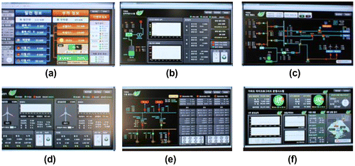
Fig. (a) shows the dashboard where the renewable energy generation information and load information can be viewed and Fig. (b) depicts information regarding energy storage amount and usable hours of the ESS. Fig. (c) shows the schematic of power flow between the renewable energy source and the system, while Fig. (d) illustrates the information on current status of the wind power generation and the status of the diesel turbine. Fig. (e) shows the status of the diesel generation and Fig. (f) illustrates the overall operation status of the microgrid. Also, power efficiency and system frequency change are visualized by EMS.
2.2. Intermittence of renewable energy sources
Technically, the output of renewable energy sources such as wind power and solar power has the characteristic of being intermittent according to the natural conditions. Hence, its contribution during the power peak time is generally low. The following factors thus have to be considered when including renewable energy in a power generation plan.
In the case of solar power, the daily insolation pattern is maintained over time duration ranging between 10 and 12 h, depending on the season. Daily insolation pattern of solar power determines the energy generation output. The annual average insolation pattern of the southern part of South Korea measured over 10 h in months can be shown in Fig. (a).
Fig. 4. Intermittance of renewable energy (a) Average insolation pattern of the southern part of South Korea and (b) 3 MW wind turbine output pattern.
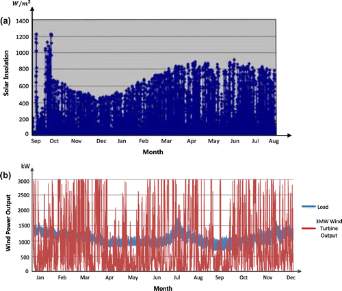
In the case of wind power, properties differ according to the regional wind speed data. Because variation of wind speed is severe, wind power shows the greatest uncertainty amongst the renewable energy sources. Despite this, wind power has high potential among renewable energy sources because its expandability to massive power generation source is high. The output of wind turbine measured in Deokjeok Island of South Korea is shown in Fig. (b). The output was measured when the wind speed is the highest.
When using renewable energy sources, the maximum and minimum power demands and seasonal, annual average power demands have to be analyzed, and then the power generation schedule has to be established accordingly. The generation schedule has to take the characteristics of the renewable energy into account. The capacity of renewable energy generation has to be determined considering the amount of demand. If renewable energy is used as the main source of a microgrid, imbalance between supply and demand can occur, as suggested in Fig. . As can be seen in Fig. (b), since the wind power generation output according to the power demand with blue-colored curve varies significantly, stable power supply becomes problematic. In a small-scale microgrid, ESS (batteries) is mainly used to compensate for this, so an assessment for ESS capacity is indispensible.
3. Desalination plant powered by microgrid
3.1. Factors to consider for desalination plant
The performance of a seawater desalination plant is determined by the raw water conditions (temperature, TDS, etc.), membrane lifespan, membrane penetration flux, operating pressure, transmembrane pressure, membrane-cleaning schedule, supply pump efficiency, filter efficiency, energy usage, and presence of recovery equipment. The raw water conditions and pump efficiency are determined during the design process. Therefore, prevention of RO performance degradation and membrane management including fouling prevention and cleaning are core aspects of desalination plant performance management. Table shows the major performance indicators of a desalination plant.
Table 1 Performance indicators of desalination plant
Desalination plants use many chemicals and highly corrosive seawater as the raw water source, and thus measurement and monitoring of the physical conditions is necessary. To do so, information of all the constituent materials of the plant must be collected and a non-destructive inspection technology should be developed. While theoretical physicochemical damage prediction and probabilistic damage occurrence prediction are necessary, diagnostic inspection to determine the plant condition is also critical. Deterioration and damage phenomena of the constituent materials and functionality of the equipment such as pump should be checked regularly.
To prevent various power-quality issues in advance, which include constant voltage variation, instantaneous voltage variation, bidirectional protection cooperation, instantaneous power failure, harmonics, and flicker, a harmonic filter, shielding, surge absorption, grounding, and an ESS can be utilized. In the microgrid, which is a low-power system, it is likely that power-quality variation and impact may be significant due to a change or accident of the supplier as well as the consumer. In the renewable energy-coupled desalination plant, solar power and wind power will be used as the major renewable energy sources. Therefore, monitoring of the voltage, current, frequency, state of charge and discharge for the ESS, wind speed, and insolation is needed.
3.2. Desalination monitoring system
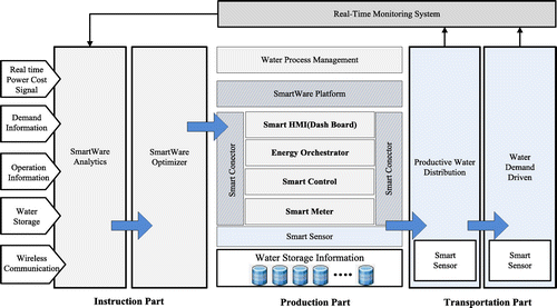
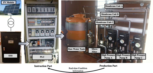
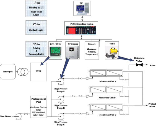
Fig. shows the structure of the desalination monitoring system. Wireless communication module in Fig. can be implemented to achieve high-speed data communications [Citation13–16]. In the instruction part, the daily production of fresh water is determined based on the water consumption, consumption pattern information, pipeline information, and water-level information. Also, an hourly operation schedule is established using real-time power costs, power output, and required daily production. In the production part, the number of operated water channels on an hourly basis is determined according to the production plan, and fresh water is produced by controlling the high pressure pump output and open percentage of rear valve. The transportation part is responsible for transferring the reservoir water-level information, point-wise demand information, and water pressure data to the instruction part after drainage and supplying of the water, which was stored in the reservoir following the production part, by operating the water supply pump. Fig. shows the actually implemented desalination plant based on the block diagram of the desalination monitoring system in Fig. .
Solar cell (PV module, photovoltaic module) is connected to ESS and the ESS supplies power to desalination plant. Power grid is also connected to the ESS, so that dual-mode operation of the ESS is enabled. Overall control of desalination is carried out by programmable logic controller (PLC). Three high-pressure pumps with respective variable frequency drive (VFD) are placed before membrane for RO. By the instructions from instruction part, water production is performed accordingly. For pre-filtering before RO process, micro filter is utilized. Retentate valve, which is not visible in Fig. , as well as high-pressure pump determine transmembrane pressure.
The functional block diagram of the desalination plant in Fig. is shown in Fig. . In the pretreatment (prefiltering) part, excessive dissolved solids in the raw water source are primarily removed, thereby reducing the TDS of the raw water reaching the membrane and increasing the equipment efficiency. The VFD controls the pump pressure according to the frequency conversion of 0–60 Hz, and the retentate valve operates with the pump and maintains constant pressure applied to the membrane, for example, seawater—60 bar and brackish water—12 bar. Here, rather than changing the pump pressure, adjusting the degree of retentate valve opening is better for extending the membrane lifespan. When the pressure applied on the membrane drops, fouling or accumulation of rejected materials and particles on the membrane front increases, reducing the permeate flux of the fresh water. Raising the pump pressure to recover from this will damage the membrane, thus adversely affecting the membrane lifespan. The retentate valve of the implemented system has a similar variation of resistance according to the percentage open as shown in Fig. . The membrane resistance is increased over time because of fouling [Citation18–20]. In summary, elements that need to be controlled in the desalination plant are: (i) raw water pump on/off, (ii) membrane operating pressure, (iii) retentate valve, (iv) RO pump operating frequency, and (v) overall system operation scheduling, all while taking into consideration the high- and low-pressure limits of the membrane.
Fig. 8. Transmembrane pressure control and retentate valve resistance according to percentage open: (a) Transmembrane pressure control and (b) Valve resistance according to percentage open [Citation17].
![Fig. 8. Transmembrane pressure control and retentate valve resistance according to percentage open: (a) Transmembrane pressure control and (b) Valve resistance according to percentage open [Citation17].](/cms/asset/d65b21fd-d91c-4d79-9885-2dd13a0d411b/tdwt_a_982960_f0008_oc.gif)
4. Cost-efficient desalination
Consider a grid-connected microgrid with renewable energy resource. The desalination plant consumes energy which can be generated by in-house microgrid or purchased from outside, e.g. from power grid. On the other hand, when the amount of electricity generated is greater than the consumption by the plant, the electricity generated by microgrid can be sold to demanders of small- and medium-capacity electricity. The demand response (DR) market is fit for such sales of overplus electricity to demanders of small- and medium-capacity electricity. The real-time monitoring of desalination is performed through the data analysis and optimization engine. If optimization is to maximize total profit per hour as following(2)
optimization is performed to maximize profit under the constraint of the daily production of water, participation in the DR market, and the timing that the energy consumption minimization mode is selected. When there is no overplus electricity, the first two terms in (2) become zero, so that energy consumption minimization during daily production of water is the optimization of plant operation.
5. Conclusion
This paper described a desalination process powered by a microgrid. An actual desalination plant powered by a microgrid has been implemented. Overall control of the desalination plant is carried out by a PLC and status of water production is monitored by EMS. The microgrid-powered desalination process is reviewed from the perspective of individual modules. Considering the importance of microgrid powering diverse applications and the criticality of desalination processes for many water-hungry countries, this work is expected to be further developed.
Acknowledgment
This research was supported by Ministry of Land, Infrastructure and Transport (MOLIT) as Railroad Specialized Graduate School and this research was supported by a grant from Railroad Technology Research Program (Technology development on the positioning detection of railroad with high precision.) funded by Ministry of Land, Infrastructure and Transport of Korean government.
References
- H.T. EI-Dessouky, H.M. Ettouney, Y. Al-Roumi, Multi-stage flash desalination: Present and future outlook, Chem. Eng. J. 73(2) (1999) 173–190.
- M. Al-Shammiri, M. Safar, Multi-effect distillation plants: State of the art, Desalination 126 (1999) 45–59.10.1016/S0011-9164(99)00154-X
- C. Fritzmann, J. Löwenberg, T. Wintgens, T. Melin, State-of-the-art of reverse osmosis desalination, Desalination 216 (2007) 1–76.10.1016/j.desal.2006.12.009
- L.F. Greenlee, D.F. Lawler, B.D. Freeman, B. Marrot, P. Moulin, Reverse osmosis desalination: Water sources, technology, and today’s challenges, Water Res. 43(9) (2009) 2317–2348.
- Renewable Energy Desalination, An Emerging Solution to Close the Water Gap in the Middle East and North Africa, World Bank, Washington, DC, 2012, ISBN (paper): 978-0-8213-8838-9.
- M.M. Schenkeveld, R. Morris, B. Budding, J. Helmer, S. Innanen, Seawater and Brackish Water Desalination in the Middle Ease, North Africa and Central Asia—A Review of Key issues and Experience in Six Countries (Algeria, Tunisia, Jordan, Uzbekistan, Malta, Cyprus), World Bank, 2004. Available from: <http://www.worldbank.org/watsan/bnwp>.
- GWI DesalData: Desalination Markets 2010. Available from: <www.desaldata.com>.
- J.R. McCutcheon, R.L. McGinnis, M. Elimelech, A novel ammonia—carbon dioxide forward (direct) osmosis desalination process, Desalination 174 (2005) 1–11.10.1016/j.desal.2004.11.002
- K. Park, S. Hong, J. Lee, K. Kang, Y. Lee, M. Ha, J. Lee, A new apparatus for seawater desalination by gas hydrate process and removal characteristics of dissolved minerals (Na+, Mg2+, Ca2+, K+, B3+), Desalination 274 (2011) 91–96.10.1016/j.desal.2011.01.084
- S. Lee, S. Sarp, D. Jeon, J. Kim, Smart water grid: The future water management platform, Desalin. Water Treat. ( in press), doi: 10.1080/19443994.2014.917887 .
- V.C. Gungor, B. Lu, G.P. Hancke, Opportunities and challenges of wireless sensor networks in smart grid, IEEE Trans. Ind. Electron. 57(10) (2010) 3557–3564.10.1109/TIE.2009.2039455
- P. Siano, C. Cecati, C. Citro, P. Siano, Smart operation of wind turbines and diesel generators according to economic criteria, IEEE Trans. Ind. Electron. 58(10) (2011) 4514–4525.
- E. Hong, Y. Park, S. Lim, D. Har, Adaptive phase rotation of OFDM signals for PAPR reduction, IEEE Trans. Consum. Electron. 57(4) (2011) 1491–1495.10.1109/TCE.2011.6131116
- E. Hong, S. Min, D. Har, SLM-based OFDM system without side information for data recovery, IEE Electron. Lett. 46(3) (2010) 255–256.10.1049/el.2010.3323
- H. Kim, E. Hong, C. Ahn, D. Har, A pilot symbol pattern enabling data recovery without side information in PTS-based OFDM systems, IEEE Trans. Broadcast. 57(2) (2011) 307–312.
- J. Park, E. Hong, D. Har, Low complexity data decoding for SLM-based OFDM systems without side information, IEEE Commun. Lett. 15(6) (2011) 611–613.
- A.R. Bartman, P.D. Christofides, Y. Cohen, Nonlinear model-based control of an experimental reverse-osmosis water desalination system, Ind. Eng. Chem. Res. 48(13) (2009) 6126–6136.10.1021/ie900322x
- Y. Lee, Y. Lee, D. Kim, M. Park, D. Yang, J. Kim, A fouling model for simulating long-term performance of SWRO desalination process, J. Membr. Sci. 401--402 (2012) 282–291.10.1016/j.memsci.2012.02.016
- K. Chen, L. Song, S. Ong, W. Ng, The development of membrane fouling in full-scale RO processes, J. Membr. Sci. 232 (2004) 63–72.10.1016/j.memsci.2003.11.028
- X. Hu, E. Bekassy-Molnar, A. Koris, Study of modelling transmembrane pressure and gel resistance in ultrafiltration of oily emulsion, Desalination 163 (2004) 355–360.10.1016/S0011-9164(04)90208-1

