
ABSTRACT
The presence of process-induced strains induced by various manufacturing and operational factors is one of the characteristics of polymer composite materials (PCM). Conventional methods of registration and evaluation of process-induced strains can be laborious, time-consuming and demanding in terms of technical applications. The employment of embedded fibre-optic strain sensors (FOSS) offers a real prospect of measuring residual strains. This paper demonstrates the potential for using embedded FOSS for recording technological strains in a PCM plate. The PCM plate is manufactured from prepreg, using the direct compression-moulding method. In this method, the prepared reinforcing package is placed inside a mould, heated, and then exposed to compaction pressure. The examined technology can be used for positioning FOSS between the layers of the composite material. Fibre-optic sensors, interacting with the material of the examined object, make it possible to register the evolution of the strain process during all stages of polymer-composite formation. FOSS data were recorded with interrogator ASTRO X 327. The obtained data were processed using specially developed algorithms.
1. Introduction
Polymer composite materials (PCM) have advantages over traditional materials: the ability to create different shapes with desired properties, high resistance to fatigue and corrosion, and low specific gravity. However, during exploitation, multi-layer composites have a high probability of developing defects and sustaining damage, which, among other factors, is determined by the technological process of PCM creation and the presence of process-induced strains in the material. Traditional methods of assessing process-induced strains can be laborious, time-consuming and demanding in terms of technical applications.
Among the various sensors for measuring mechanical damage to materials, FOSS, based on Bragg grating, have the advantage of a greater sensitivity when compared with other sensors, immunity to electrical noise, availability, easy integration with other equipment, remote control, and the ability to measure various physical and mechanical values. Additionally, for composite materials there is the possibility of FOSS being embedded in material during manufacture. Material with embedded sensors may be considered a type of SMART material. Embedding FOSS during PCM manufacture allows the process-induced strains to be registered and reveals the control capabilities of these strains.
Nevertheless, some limitations to the use of smart-material become evident in their technological development. One of the most significant problems is the instability of the mechanical characteristics of the final product, which is owing to various factors, such as the variation in the quality of the raw materials between batches and the different epoxy binder content in different parts of the prepreg within any one batch, as well as the moulding method used. To improve the quality of the PCM, control of the curing process becomes necessary. In study [Citation1] it is said that the composite materials are subjected to significant physical and chemical changes during the curing process. The effect of curing on the characteristics of composite materials is influenced by factors such as temperature, resin viscosity and internal stresses. As a result, in recent years, monitoring of the process of PCM creation has become an urgent research task. The authors of [Citation2] present a record of the curing cycle of a layered composite with embedded fibres on Bragg gratings. In this study, the PCM workpiece was placed inside a vacuum bag and cured outside the autoclave under given temperature conditions. It became impossible to perform the curing process in an autoclave due to hermiticity of the working area. The autoclave hermiticity makes it impossible to connect the optical fibre to the reader without interfering with the autoclave design. The temperature was measured by placing a thermocouple close to the sample. In [Citation3], the influence of residual stresses on fatigue life and the accuracy of the dimensions of composite structures were investigated. It was confirmed that the value of the residual stresses can be significantly reduced by choosing a rational curing regime. These results were obtained using FBG (Fibre-optic Bragg grating) and dielectrometry.
Using FOSS, a study was conducted in [Citation4] of the residual stresses arising in the manufacture of panels made of a carbon-fibre composite laminate with an epoxy binder. The technological effects of temperature and the external pressure of the gas through the vacuum bag were considered. The embedded FOSS measured the development of process-induced strains in real time in the PCM production process. This information was used to analyse the spatial distribution of resin throughout the product.
In study [Citation5], the efficiency is examined of the measurement of process-induced strains during the manufacturing process of the mast of a sailing boat in the autoclave moulding. Study [Citation6] provides an experimental comparison between FOSS measurements and conventional resistive strain gauges. The sensitivity and accuracy of static tensile tests was demonstrated, as well as the possibility of monitoring strains using FOSS. The emphasis in [Citation7] is placed on the fact that the fibre-optic strain sensors with Bragg gratings are an excellent non-destructive tool for measuring internal strains in composite material. In study [Citation8], the presence of residual stresses, which appeared during the manufacturing process, was indicated as one of the causes of FOSS spectrum distortion. The ability to use information about the internal and surface strains, obtained by FOSS with the aim of quantifying damage and residual performance designs, is described in [Citation9].
The diminutive size and shape of the FOSS allow them to be embedded directly between the composite layers. This provides the possibility of monitoring the composite structure, from the beginning of composite production up to its operating conditions [Citation10,Citation11]. The embedding of FOSS into the composite system may allow defects to be eliminated more efficiently during the production process [Citation12]. Various methods for efficient and reliable embedding of FOSS into composite structures were studied. It was shown that the same sensors can be used for verifying compliance with specifications or for quality assessment, as well as for monitoring structural integrity over the structures serviceable life, with the help of structural monitoring systems that operate in real time.
However, the existing literature does not fully disclose the specifics of the formation of process-induced strains that occur in the process of PCM production using the compression-moulding method. In this paper, the results are examined of a study of the possibility of using FBG sensors in a specific technology for PCM manufacturing from prepreg by direct compression in moulds. An essential factor affecting the deformation of the package from the prepreg is its interaction with the mould. In this case, the deformation process in PCM is determined principally by the temperature deformation of the massive metal mould plates, between which the workpiece is located. The possibility of embedding the FOSS between the layers of the composite material formed for strain registration is demonstrated in this paper. The process of embedding FOSS in PCM is described. The evolution of the strain process of the polymer composite material formation is shown at all stages of the manufacturing process.
2. Prepreg technologies and methods for compression moulding
This section contains a description of the technological process of embedding FOSS into PCM. One of the necessary conditions for this process is integrity of the fibre material during the manufacturing process.
A distinctive feature of the designs made from polymer composite materials is that materials and products are created simultaneously. Predefined geometrical dimensions and shape are given to the design. As a result, the physical and mechanical characteristics of the product depend on the design features and the technological features of the manufacturing process. Considering these features of PCM design, the issue of control of the stress-strain state in the manufacturing process, as well as in the subsequent operation of the structure, becomes relevant.
The direct compression method is similar to the stamping method, during which a prepared reinforcement package from prepreg is placed into a mould, heated, and exposed to pressure. The mould consists of two massive metal plates, between which is located a reinforcement package prepared from prepreg. Two parameters determine the pressing mode: temperature and pressure. The temperature influence is formed by applying external heat sources to the moulds. The pressure is created by external mechanical devices, which ensure the compression of the plates of the mould. The properties of the filler and the epoxy binder of the PCM dictate the mode by which these parameters are changed at set intervals. These regimes determine the sequence through which the stages of evolution of the workpiece material (polymerization, curing, glass transition, etc.) pass, as well as dictating the formation of technological and process-induced strains [Citation13].
Pressing technology affords the possibility of full process mechanization, the ability to manufacture complex details with high-precision implementation and with a surface that does not require a mechanical treatment [Citation14]. This technology can be applied using a prepreg composite material, where as binder can be used thermosetting and thermoplastic polymer. The use of embedded FOSS in the workpiece makes it possible to control the temperature and process-induced strain occurring in the workpiece during all technological stages.
The technological process of embedding FOSS in composite material includes several basic steps. First, the reinforcing material cutting on the plotter Zund G3 L-2500 is carried out. A further 20 layers of reinforcing fibreglass prepreg are laid out on varnished cloth. A predefined scheme of embedding two optical fibres, with five FOSS on each, between the tenth and eleventh layers of reinforcing material, was specified.
The technology of PCM manufacturing from a received workpiece consists of the following operations:
temperature increase from room temperature to 120ºC at a rate of 3ºC/min and with simultaneous increase of pressure up to 0.1 MPa;
a delay of 1 hour, at a temperature of 120ºC and pressure of 0.1 MPa; (at this stage, the polymerization process is complete and the epoxy binder begins to cure);
increase of compression-mould temperature to 180ºC at a rate of 3ºC/min and with simultaneous increase of pressure up to 0.3 MPa;
a delay of 4 hours at a temperature of 180ºC and pressure of 0.3 MPa; (at this stage, the curing process is complete and the epoxy binder assumes a highly elastic state);
cooling of the compression mould at a rate of 3ºC/min until the temperature reaches 55ºC (at a temperature in the vicinity of 120ºC, there is a relaxation of the binder (glass transition) from the highly elastic state to the vitrified);
decompression to zero.
The FOSS that is embedded into the PCM allows the registering of strains in online mode at all stages of the technological process. Data registration was carried out with the help of interrogator ASTRO X 327. One of the fibre-optic sensors was not embedded in the PCM plate. This sensor was located next to the mould, and recorded the temperature of the mould.
3. Basic relationships between strain, temperature and optical characteristics of the fibre-optic bragg gratings
As is known from [Citation15], the basic relationship for a fibre-optic sensor based on Bragg gratings is:
where – the wavelength of the basic reflected optical signal from the Bragg grating, n – effective refractive index of lightguide at a given wavelength,
– the length of FBG period.
From the relationship (1) follows the expression that allows us to determine the relative change in the length of the optical signal from the temperature and longitudinal strain of the fibre in the linear approximation (2):
In the finite increment expression, (2) takes the form of a well-known expression [Citation16]:
where: ,
– the temperature in the vicinity of the sensor at the current time
;
– the temperature in the vicinity of the sensor in the initial time moment;
,
– value of the wavelength at time
,
– the value of the wavelength at the initial time moment;
– coefficient of linear temperature expansion (CLTE);
– thermo-optical coefficient;
– longitudinal strain of a section of an optical fibre with FBG, caused by external mechanical action;
– Poisson’s ratio;
and
– Pockels coefficients in the optical stress tensor.
It should be noted that for optical fibres made of quartz the coefficient of linear temperature expansion and the thermo-optical coefficient
apply. From a comparison of these quantities it follows that the dominant effect of temperature on the change in wavelength
is determined by the thermo-optical coefficient
. The right side of expression (3) is obtained from the assumption that the cylindrical surface of a section of an optical fibre with a Bragg grating is free of any external mechanical action. For the optical fibres made of quartz the following coefficients are used:
,
,
,
[Citation17]. Due to this in the expression (3) the multiplier next to
will take form:
Expression (3) makes it possible to determine the strain values of the FOSS embedded in the material of the investigated object under conditions of time-varying temperature and external mechanical influences:
Here: ,
– experimentally measured values.
To measure the fall in temperature, an additional FOSS can be used if it is free from external mechanical action and it is maintained at the same temperature as the sensor measuring strain. In this, case to determine the following relation is valid:
4. Processing data obtained from FOSS
During the direct compression moulding process, the initial and current
wavelengths of the reflected signal were recorded. The values of these quantities, respectively, at the initial time and after the completion of the technological process for two fibre-optic lines each containing five sensors, are given in and . The wavelength values for a fibre-optic sensor that acts as a temperature recorder are also given in these tables. The readings of the temperature sensor based on FBG were controlled by an autonomous temperature recorder, EClerk-USB-2Pt. The accuracy of this independent temperature recorder is
C. Also, as a sensitive element, the thermal resistance device, TC
r-K2-Pt1000-B2 was used.
Table 1. The values of the wavelengths for the FBG sensors at the initial moment of the technological process.
Table 2. The values of the wavelengths for the FBG sensors at the end of technological process.
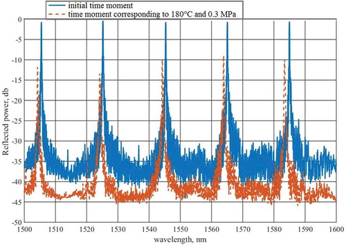
The measured values of the amplitudes of the reflected signals obtained from the five sensors located on Line 1 are shown in . The graph shows the distribution of the wavelengths of the reflected signal, while the peak maximum values of the reflected signal correspond to the basic wavelengths of the five sensors. The blue line corresponds to the beginning of the technological process. The red line corresponds to the initial moment at the stage of delay of the workpiece where the temperature is 180ºC and level of pressure at 0.3 MPa. The shift of the maxima of the blue graph relative to red allows us to determine the change in the basic wavelength
of the reflected signal at each sensor, which is caused by the total effect of mechanical strain and temperature.
Figure 1. The wavelengths distribution of the reflected signal for the five sensors of Line 1.
represents an enlarged fragment of , which refers to the FBG N 3 (medium peak). From this graph, it follows that, in the determination of
, problems associated with the ambiguity of estimating the location of the peak values of the graph along the horizontal coordinate occur (red line in ). This situation occurs at some stages of the technological process. To solve this problem, a special algorithm was proposed that allows us to determine the value of
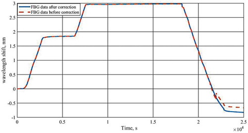
for any stage of the process in the online mode. The algorithm is based on the methods of filtering and interpolating the original data. shows the result of the algorithm operation when correcting the data recorded by FBG N
3. The change in the wavelength of the main reflected signal of this sensor is shown throughout the entire technological cycle. The effect of correction of observational data is visible on the plot of the graph corresponding to the completion of the technological process cooling of the workpiece (2
10
t
2.5
10
).
Figure 2. Changes in the reflected spectrum of FBG N 3.
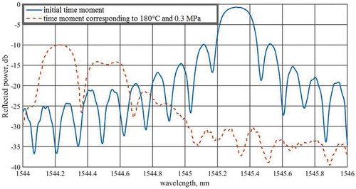
Figure 3. The result of using the correction algorithm for the FBG N 3.
5. Data registration in real time
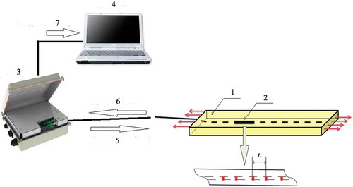
shows the registration scheme of process-induced strains in PCM in real time, as received by FOSS, where 1 – sample, 2 – segment of optical fibre with FOSS, 3 – interrogator, 4 – computer, 5 – broadband spectrum, 6 – reflected spectrum, 7 – output to computer, 8 – particular FBG, acting as a temperature sensor.
Figure 4. Scheme of data registration in real time.
To calculate the temperature according to the FBG data, the following dependence was used:
where – changes in the Bragg resonant wavelength;
– temperature changes.
From the relationship (7), the following expression was obtained for calculating the temperature changes according to the FOSS data with respect to :
or
where – initial temperature value.
The missing coefficients are found from FOSS data taken at the points in the moulding process where the temperature reached 120ºC and 180ºC, respectively, starting from the system of equations obtained from expression (7).
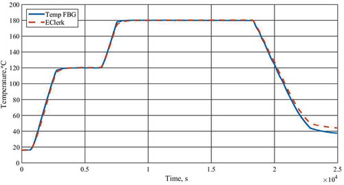
shows the graphical dependencies that were obtained with the help of a particular FBG, acting as a temperature sensor, and also with the help of an independent temperature recorder, EClerk-USB-2Pt. It should be noted that the data from the particular FBG (which was located near to the mould) correlate well with the data from independent temperature recorder, EClerk-USB-2Pt. The embedded fibre-optic sensor, interacting with the material, allows recording of the changes in the wavelength of the reflected spectrum using the interrogator.
Figure 5. Temperature data from partucular FBG and recorder EClerk-USB-2Pt.
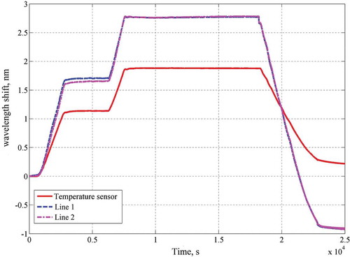
The history of the strain process in the polymer composite material formation at all technological stages of its production is presented in . The red line marks the data from the temperature sensor. Here, Line 1 (the dotted blue curve) is the averaged results for the five sensors located on Lines 1 and Line 2 (the dash-dotted crimson curve) is the averaged results for the sensors on Line 2.
Figure 6. The averaged FOSS data during the whole process of PCM formation.
From relationship (3) it follows that the change detected in the basic wavelength of the reflected spectrum is determined not only by technological strains, but also by temperature changes . Here
– the temperature in the vicinity of the sensor at the current time
;
– the temperature in the vicinity of the sensor in the initial time moment.
Applying the recorded data to the relationship (5) during the whole process of PCM formation, and subtracting the temperature component of the strain through relationship (6), the process-induced strains, formed during the whole process of PCM manufacturing, were obtained.
On the averaged strain dependencies are shown from the data of five FBG, located on Lines 1 (dashed blue curve) and 2 (dash-dotted crimson curve) optical fibres, respectively.
Figure 7. FOSS data in the strain.
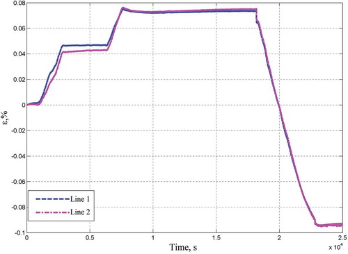
These dependencies indicate the presence of significant process-induced strains in the PCM throughout the moulding process, including the moment of its termination. The level of process-induced strains determines the levels of stability of the final dimensions and shape of the product.
6. Conclusions
In this paper, the technology of embedding FOSS into a workpiece during PCM manufacturing by direct compression-moulding method was described. The workpiece is formed from 20 layers of fibreglass prepreg. Experimental results, demonstrating the change in the wavelengths of the basic reflected signal from the embedded FOSS on Bragg gratings during the technological process of direct compression-moulding in online mode, were obtained. The results of using the developed algorithm for correcting the experimental results on the wavelength change of the reflected signal are demonstrated. The results demonstrating the evolution of process-induced strains in the PCM manufacturing throughout the technological process are shown. The obtained experimental results are useful for assessing the level of the PCMs stressed state at all stages of the direct compression-moulding process. These results can be used to evaluate the stress-strain state in all components of the PCM, that is, in epoxy binder and fillers.
Disclosure statement
No potential conflict of interest was reported by the authors.
Additional information
Funding
References
- Y. Qiu, Q.-B. Wang, H.-T. Zhao, J. Chen, and -Y.-Y. Wang, Review on composite structural health monitoring based on fiber Bragg grating sensing principle, J. Shanghai Jiaotong Univ. 18 (2) (2013), pp. 129–139. doi:10.1007/s12204-013-1375-4
- N. Lammens, D. Kinet, K. Chah, G. Luyckx, C. Caucheteur, J. Degrieck, and P. Mgret, Residual strain monitoring of out-of-autoclave cured parts by use of polarization dependent loss measurements in embedded optical fiber Bragg gratings, Compos. Part. Appl. Sci. Manuf. 52 (2013), pp. 38–44. doi:10.1016/j.compositesa.2013.05.005
- H.S. Kim, S.H. Yoo, and S.H. Chang, In situ monitoring of the strain evolution and curing reaction of composite laminates to reduce the thermal residual stress using FBG sensor and dielectrometry, Compos. Part. B Eng. 44 (1) (2013), pp. 446–452. doi:10.1016/j.compositesb.2012.04.021
- D.M. Snchez, M. Gresil, and C. Soutis, Distributed internal strain measurement during composite manufacturing using optical fibre sensors, Compos. Sci. Technol. 120 (2015), pp. 49–57. doi:10.1016/j.compscitech.2015.09.023
- R. Di Sante and L. Donati, Strain monitoring with embedded fiber Bragg gratings in advanced composite structures for nautical applications, Meas 46 (2013), pp. 2118–2126. doi:10.1016/j.measurement.2013.03.009
- J. Guemes and J. Menendez, Response of Bragg grating fibre-optic sensors when embedded in composite laminates, Compos. Sci. Technol. 62 (2002), pp. 959–966. doi:10.1016/S0266-3538(02)00010-6
- F. Colpo, L. Humbert, and J. Botsis, Characterisation of residual stresses in a single fibre composite with FBG sensor, Compos. Sci. Technol. 67 (2007), pp. 1830–1841. doi:10.1016/j.compscitech.2006.10.024
- K. Kuang, R. Kenny, M. Whelan, W. Cantwell, and P. Chalker, Embedded fibre Bragg grating sensors in advanced composite materials, Compos. Sci. Technol. 61 (2001), pp. 1379–1387. doi:10.1016/S0266-3538(01)00037-9
- F. Bosia, J. Botsis, M. Facchini, and P. Giaccari, Deformation characteristics of composite laminatespart I: Speckle interferometry and embedded Bragg grating sensor measurements, Compos. Sci. Technol. 62 (2002), pp. 41–54. doi:10.1016/S0266-3538(01)00183-X
- H.-K. Kang, D.-H. Kang, H.-J. Bang, C.-S. Hong, and C.-G. Kim, Cure monitoring of composite laminates using fiber optic sensors, Smart mater. Struct. 11 (2002), .pp. 279–287. doi:10.1088/0964-1726/11/2/311
- L. Khoun, R. De Oliveira, R. Michaud, and P.V. Hubert, Investigation of process-induced strains development by fibre Bragg grating sensors in resin transfer moulded composites, Compos. Part. 42 (2011), pp. 274–282. doi:10.1016/j.compositesa.2010.11.013
- S. Minakuchi, T. Umehara, K. Takagaki, Y. Ito, and N. Takeda, Life cycle monitoring and advanced quality assurance of L-shaped composite corner part using embedded fiber-optic sensor, Compos. Part. 48 (2013), pp. 153–161. doi:10.1016/j.compositesa.2013.01.009
- I.O. Glot, L.A. Golotina, and I.N. Shardakov, Experimental and theoretical study of the peculiarities of the thermo-mechanical behavior of semicrystalline polymers, Polym. Comp. 36 (6) (2015), pp. 1055–1062. doi:10.1002/pc.23463
- R. De Oliveira, S. Lavanchy, R. Chatton, D. Costantini, V. Michaud, R. Salath, and J.-A. Mðµnson, Experimental investigation of the effect of the mould thermal expansion on the development of internal stresses during carbon fibre composite processing, Compos. Part. 39 (2008), pp. 1083–1090. doi:10.1016/j.compositesa.2008.04.011
- I.N. Kulchin, Distributed Fiber-Optic Measure Systems, Fuzmatlit, Moscow, 2001.
- E. Kablov, D. Sivakov, I. Guliaev, K. Sorokin, M. Fedotov, E. Dianov, S. Vasilev, and O. Medvedkov, The use of optical fiber as strain gauges in polymer composite materials, Encyclopedic Guide. 3 (2010), pp. 1–11.
- A. Bertholds and R. Dändliker, Deterination of the individual strain-optic coefficients in single-mode optical fibers, J. Light. Technol. 6 (1) (1988), pp. 17–20. doi:10.1109/50.3956