
ABSTRACT
This paper considers the problem of natural vibrations of a deformable structure containing elements made of piezomaterials. The piezoelectric elements are connected through electrodes to an external electric circuit, which consists of resistive, inductive and capacitive elements. Based on the solution of this problem, the parameters of external electric circuits are searched for to allow optimal passive control of the structural vibrations. The solution to the problem is complex natural vibration frequencies, the real part of which corresponds to the circular eigenfrequency of vibrations and the imaginary part corresponds to its damping rate (damping ratio). The analysis of behaviour of the imaginary parts of complex eigenfrequencies in the space of external circuit parameters allows one to damp given modes of structure vibrations. The effectiveness of the proposed approach is demonstrated using a cantilever-clamped plate and a shell structure in the form of a semi-cylinder connected to series resonant circuits.
1. Introduction
The problem of controlling the dynamic behaviour of structures experiencing vibrations, in particular, the problem of damping the specified modes of structural vibrations, does not lose its relevance, despite a great number of approaches to its solution. Since the advent of high-tech and miniature structures, this problem required non-standard solutions, and the development of new approaches to vibration dampening. One way to solve this problem is to equip the structure with piezoelectric elements connected to external passive electrical circuits. In this case, a piezoelectric element serves to transform the mechanical energy of vibrations into electrical energy, which is then dissipated in the external circuit.
The early studies, which considered the possibility of controlling the dynamic characteristics of structures via connecting the attached piezoelectric element to additional electrical impedance, dated back to the late 70-s of the past century [Citation1]. However, the first paper that really attempted a detailed study of this approach was presented by Hagood and Von Flotow [Citation2].
This work describes the key features of structure behaviour in the presence of shunted piezoelectric elements, including the effect of external circuits on the mechanical characteristics of the structure. It also introduces an approach for selecting optimal parameters for the external circuits, which is based on the analysis of the transfer function of the system with a shunted piezoelectric element. The general principle of constructing a transfer function suggests that the system with distributed parameters (with an infinite number of degrees of freedom) is reduced to the system with lumped parameters (with a finite number of degrees of freedom). This approach is applied to structures of various types (flat, spatial). The form of a transfer function depends on specific boundary conditions, external forces, etc.
The analysis of literature [Citation2–Citation19] shows that, in terms of optimal damping this approach still remains the most popular one in the analysis of dynamic behaviour of systems with shunted piezoelectrics. Apart from that, there are some techniques to obtain optimal parameters of the external circuit within this approach, such as optimization by H2- or H∞-norms of transfer function [Citation4,Citation13,Citation20,Citation21], optimisation by equality of transfer function magnitudes [Citation2,Citation3,Citation6], and optimisation by transfer function pole placement [Citation5,Citation6,Citation14]. All of these lead to different optimal values of circuit parameters for the same structure, depending on choice of transfer function and optimisation criterion [Citation2,Citation6,Citation13].
One of the advantages of the approach based on the construction of the transfer function, is the possibility of obtaining analytical formulas for determining the optimum values of the parameters for shunting circuits. In comparison with the approach based on the construction of a transfer function, a simulation of the dynamic behavior of an electroviscoelastic structure with external electric circuits based on the methods of solid mechanics for systems with distributed parameters is a more general approach.
A quantitative estimate of the dissipative properties can be obtained from the solution of two problems. The first is related to the consideration of free vibrations. In this case, the dissipation of the system manifests itself in damping of the vibrations, and the rate of decay of vibrations quantitatively estimates the dissipative properties of the system being simulated. The second problem concerns steady-state forced vibrations, and the dissipative properties of the system are estimated based on the values of amplitudes in resonance regimes. A search for optimal variants by numerical simulation methods is eventually associated with an exhaustive search of solutions at different values of optimization parameters (in our case, parameters that determine the elements of the electrical circuit). When the problem on forced steady-state forced vibrations is applied to the problem under consideration, the obtained amplitude-frequency responses of displacements at various points of the object under study is considered to be a criterion for optimization search. This specifies in our case one of the main drawbacks of the problem on forced steady-state vibrations, since the obtaining of an amplitude-frequency responses requires a fairly ample amount of solution results obtained at different values of frequencies of excitation, assuming all other parameters of the modeled system remain unchanged. When using the problem of free damped vibrations with initial conditions, it is necessary to consider different options of initial excitation. In addition, the results of optimal location study based on the abovementioned problems may be non-optimal at varying external loads.
The proposed problem of natural vibrations does not have such drawbacks, which makes it effective in optimizing the dynamic behavior of electroelastic structures with external electric circuits. The result of solving this problem are complex natural frequencies i
, where
corresponds to the natural frequency,
corresponds to the damping ratio of this frequency, i
is the imaginary unit [Citation22].
In a previous work [Citation23], it was shown that the above problem is most convenient and informative from the viewpoint of optimisation of its dynamic characteristics for a structure with piezoelectric elements and external circuits, because it allows one to directly determine the relationship between the damping ratio and the parameters of the external electric circuit.
2. Mathematical statement of the problem
A piecewise-homogenious body of volume , where volume
consists of N homogeneous elastic parts and volume
consists electroelastic (piezoelectric) elements is established as the object under study. A part of
volume surface is covered with electrodes.
The variational equation of motion of the body consisting of elastic and piezoelectric elements was derived on the basis of the linear theory of elasticity relations and quasi-static Maxwells equations [Citation24–Citation28]:
where, ,
are the components of electric flux density and electric field intensity vectors, respectively;
represents the components of the symmetric Cauchy stress tensor;
represents the components of the linear strain tensor;
are the components of the displacement vector;
is the mass density of the
-th constituent of the piecewise-homogeneous body of
volume;
is the mass density of the piezoelectric material of the electroelastic body of
volume;
is part of the V volume surface where the surface loads
are prescribed;
is the surface of the piezoelectric body of the
volume, where part of the surface
is covered with electrodes and part of the surfaces
is without electrodes;
is the free electric charge surface density;
is the electric potential;
is the variation of the corresponding variable.
For the electric field, the potentiality condition is fulfilled and can be written as:
For the case of isothermal processes, the following physical relations are valid. For the elastic parts of the volume:
and for the piezoelectric elements of the volume:
where and
are the components of the fourth-rank tensors of elastic constants and,
are the components of the third-rank tensor of piezoelectric coefficients and
are the components of the second-rank tensor of dielectric coefficients (
).
For the electroelastic problem under study, the boundary conditions can be divided into two types: mechanical and electrical. The mechanical boundary conditions are written by analogy with problems in the theory of elasticity:
where is the part of the surface where the stresses
are prescribed;
is the part of the surface where the components of the displacement vector
are given and
are the components of the unit normal vector for the
surface.
For the non-electrode parts of the surface of a piezoelectric body of volume
the electric boundary conditions are absent due to the fact that these parts of the surface are non-conductive and hence there are no free electric charges on them. Taking into account the used form of Maxwells equations, one can write this condition in the following way:
The electric boundary conditions are dependent on the way electric energy transmission to the piezoelectric body is achieved. The supplying and withdrawal of electrical energy for the piezoelectric body is performed with the aid of the electrode coverage on parts of the bodys surface. Further, it is implied that the electrode coverages are thin ideal conductors with negligible mass. The presence of electrode coverage at the surface makes it an equipotential surface.
The specific form of boundary conditions for the electric component of the state vector depends on the type of energy sources, but generally, one can use well-known models for the energy sources from electrical engineering, such as the current generator and voltage generator models.
Supposing one of the electrode surfaces of the piezoelectric element is grounded, i.e. it has a zero-value electric potential, one can write the electric boundary condition for this part of the surface as follows:
where is the part of the electrode surface
of volume
where the electric potential is prescribed. In the case of the absence of an external power supply, the other parts of the electrode surface can be free (in this case, the open circuit mode is realised) or one can set condition (7) on them (in this case, the short circuit mode is realised).
By using the electrode surfaces, one can attach external electric circuits with an arbitrary configuration to the system under consideration, which could include resistive elements (), capacitive elements (
) or inductive elements (
). When these circuits are not supplied by an external power source, they are classed as internal elements of the system and then the following term should be added to Equation (1):
This term takes into account all the internal works of the electric field with a potential difference
for transferring the arbitrary electric charge on the circuit elements
,
,
On the basis of some well-known relations from electrical engineering [Citation29,Citation30] one can obtain expressions for all of the terms in Equation (8). In order to do this, consider an external circuit made of a single element from among those presented in :
Figure 1. Elements of an external electrical circuit: (a) – resistance (), (b) – capacitance (
), (c) inductance (
).
- for a resistive circuit:
where ,
– electric potentials in points 1 and 2 (see (a));
- for a capacitive circuit:
where ,
– electric potentials in points 1 and 2 (see (b));
- for a inductive circuit:
where ,
– electric potentials in points 1 and 2 (see (c)).
Taking into account the form of the terms (10–12) in expression (8), the variational equation for the motion of an electro-viscoelastic body with external electric circuits takes the following form:
where the potential difference in the corresponding circuit element
;
are the quantities of the inductive, resistive and capacitive elements, respectively, and
are the values of the inductance, resistance and capacitance of the corresponding circuit elements.
For the problem of natural vibrations under zero-value boundary conditions (5,6,7), eigensolutions are sought in the following form:
where i
gives the complex natural vibration frequency, wherein
corresponds to the circular natural vibration frequency,
is the rate of its damping (the damping ratio of vibrations) and
are the natural vibration forms.
Taking into account the form of solution (14), the variational equation for the problem of the natural vibrations of an electro-viscoelastic body with external electric circuits in the case of an absence of external loads takes the following form:
A complete mathematical formulation of the problem is given in [Citation27]. The stated problem is solved by the finite element method, using the algorithm elaborated by the authors of this paper using the capabilities of the ANSYS software package and program written in FORTRAN language. By solving the system of equations, we get the spectrum of complex-conjugate natural frequencies of vibrations. On the basis of physical considerations and pursuing the objective of our study (damping of vibrations of the examined system), in what follows we take into account only complex vibration frequencies with the positive real part and the negative imaginary part
ensuring vibration damping.
3. Determination of the parameters of the shunting circuit for damping the structure vibrations
This Section presents a few examples to show the behaviour of the complex natural frequencies of the system vibrations (elastic body, piezoelement and external electric circuit) when the parameters of the external resonance electric circuit change:
1) the cantilevered rectangular plate with a piezoelectric element attached to its surface ()). The dimensions of the plate were as follows: mm,
mm,
mm. The plate was made of material with the following mechanical characteristics:
Pa,
kg/m
. The piezoelectric element was rectangular in shape with the following dimensions:
mm,
mm,
mm and located symmetrically about the plate axis at a distance of 12 mm from the clamped edge of the plate. The piezoelectric element was made of piezoceramics PZT-4 polarized in the direction of the z-axis with the following components of the matrices of material constants:
Pa,
Pa,
Pa,
Pa,
Pa,
Pa,
C/m
,
C/m
,
C/m
,
F/m,
F/m,
kg/m
. The upper and lower surfaces of the piezoelectric element were covered with electrodes;
Figure 2. Calculation schemes of structures with a piezoelectric element: (a) plate; (b) shell.
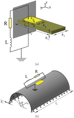
2) the thin-walled shell in the form of a semi-cylinder that is clamped at the edges and simply supported along the generatrix ()). The geometrical dimensions of the shell are as follows: mm,
mm,
mm. The shell is made of elastic isotropic material having the following characteristics:
Pa,
,
kg/m
. The piezoelectric element, which is attached to the surface of the shell, has the following dimensions: width 20 mm, thickness 0.36 mm, length 50 mm. The centre of mass of the piezoelectric element is 15 mm away from the clamped edges and is shifted by 90 degree from the simply supported generatrix along the angular coordinate. The piezoelectric element is made of peizoceramics PZT-4 polarised along the r-axis and having the similar physical and mechanical characteristics (in the cylindrical coordinate system). The upper and lower surfaces of the piezoelectric element covered by electrode layers.
As the external electric circuit, we consider the -circuit consisting of series-connected resistance (
) and inductance (
) elements. A piezoelectric element, by virtue of its nature, has capacitive properties and in the presence of the external
-circuit forms a series resonance oscillatory
-circuit. This leads to the appearance of additional eigenfrequency in the natural frequencies spectrum of the base structure, which is due to the interaction of the inductive element and the inherent capacitance of the piezoelectric element. As a result, the spectrum of the eigenfrequencies of the structure with a piezoelectric element and an external electric circuit is formed. This additional eigenfrequency can vary over a wide range due to changing the parameters of the external circuit.
Damping of vibrations of the structure with the external electric -circuit at a specified frequency is achieved by purposely tuning of this additional frequency on the frequency to be damped. To this end, by changing the value of external inductance, an additional frequency is brought closer and closer to the eigenfrequency of the structure until they coincide.
Since in the complex eigenfrequency (according to the mathematical formulation of the problem) the real part characterizes the frequency of vibrations, one of the conditions for selecting parameters of the shunting circuit can be given as
where is the real part of eigenfrequency of the host structure with attached piezoelectric element in the presence of an external circuit;
is the real part of additional electric circuit frequency integrated into the initial spectrum of eigenfrequencies.
However, the issue of whether this condition (16) fully identifies the parameters of the external electric circuit, ensuring maximum damping of structure vibrations, is still an open question.
The investigations have shown that in the space of parameters there is a set of points corresponding to different values of resistance and inductance, at which condition (16) is satisfied.
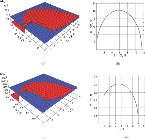
(a,b) show the behaviour of real parts of the first eigenfrequency of the structures with a shunt piezoelectric element and the vibration frequency of the electric circuit in the space of the parameters and
for structures with a piezoelectric element shunted with a series
circuit. The projections of the lines of their coincidence in the space of the parameters
and
are shown in (c,d). From the charts shown in , one can see that condition (16) is not sufficient for the unambiguous determination of the optimal parameters of the external electric circuit, since the coincidence of frequencies is observed for a set of points generating smooth spatial curves.
Figure 3. Surfaces of the real part of the first complex eigenfrequency (blue) and the frequency of the electrical circuit oscillations (red) for the plate (a) and shell (c) and the projections of their coincidence lines for the plate (b) and shell (d).
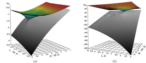
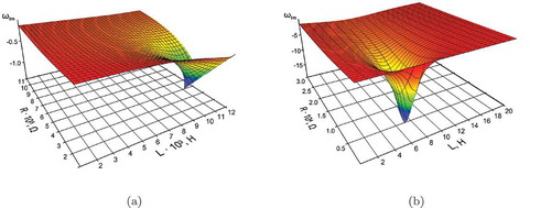
We can use the fact that the solution of the problem of natural vibrations of the smart-structure with an external electrical circuit provides a value of damping ratio for a particular frequency. Our studies have revealed that the damping ratio of vibrations of the additional frequency of the electric oscillatory circuit
varies within very wide range and has, in the space of electric circuit parameters
and
, a great number of local extrema, which appear at the instant of convergence of electric circuit damping ratio with the damping ratios
of the complex natural vibration frequencies related to the structure. illustrates the behavior of damping ratios of the first complex natural frequency of the structure (colored surface) and the complex natural frequency of the electric oscillatory circuit (gray surface) for the examined objects (plate and shell) in the domain of
electric circuit parameters.
Figure 4. Surfaces of dependence of the imaginary parts of the first complex eigenfrequency of the structure (colored) and the integrated complex frequency of oscillatory circuit (gray) on the and
parameters of the external circuit for the plate (a) and the shell (b).
The investigations performed allows stating that, for each natural vibration frequency of the structure, there exists only one global extremum of the damping ratio over the entire space of possible values of the parameters (). The maximum convergence (coincidence) of the imaginary parts of complex eigenfrequencies of structure vibrations and those of the electric oscillatory circuit is observed on the match line ( (b,d)) of the real parts of complex eigenfrequencies of vibrations of the structure and the electric oscillatory circuit, which corresponds to condition (16).
Figure 5. Surfaces of dependence of the imaginary part of the first complex eigenfrequency of the structure on the and
parameters of the external circuit for the plate (a) and the shell (b).
Since the contribution to the dynamic response of the system in the vicinity of the vibration frequency corresponding to the damped mode is made by both modes of vibrations (corresponding to the ”structural” and the ”electric” eigenfrequencies). The optimal damping will be achieved with the parameters and
corresponding to the condition
. At the same time, for these parameters
and
, the imaginary part of the ”structural” frequency
takes an extreme value. Since it is always less than or equal to the imaginary part of the ”electric” natural vibration frequency
(see ), the overall damping in the vicinity of the frequency under consideration will be as higher than the imaginary part of the complex eigenfrequency relevant to the structure would be higher (in absolute value). On this basis, the condition providing a unambiguous determination of the optimal values of shunting circuit parameters of
and
, at which the highest damping rate of the corresponding vibration mode can be reached, is written as
4. Numerical results
For the structures under consideration (), the problem of natural vibrations was solved to obtain the values of optimal parameters of the shunting circuit taking into account condition (17).
The effectiveness of this approach was verified by selecting the following shunt parameters for the plate (damping the first and second modes) and for the shell (damping the first and fourth modes of vibrations).
Many authors [Citation2–Citation14] determined the parameters of an external electric circuit required for damping the specified vibration mode based on transfer functions of various kinds. It would be of considerable importance to compare the results obtained with the help of the transfer function with the results of solving the problem of natural vibrations of the structure in the proposed mathematical formulation.
Based on the relations given in the paper of Hagood and von Flotow [Citation2], one can obtain formulas for determining the optimal parameters of resistance and inductance
of the external shunt circuit. We reproduce here the following relations for the tuning parameter
and the damping parameter
:
where is the oscillation frequency of the electric circuit;
is the
-th vibration frequency of the structure in a short circuit mode;
is the capacitance of the piezoelement, corresponding to its capacity during the
-th resonance;
is the static inherent capacitance of the piezoelement;
are the resistance and inductance of the shunt circuit [Citation2]. According to the pole placement criterion, the maximum characteristics of damping can be achieved when the tuning parameter
and the damping parameter
take on the following values:
where is the electromechanical coupling factor,
,
are the
-th natural vibration frequency of the structure with a piezoelement in open and short circuit modes. After substitution of relations (18) into (19) and simple mathematical transformations, we get relations for determining the optimal parameters of the shunt circuit
and
for damping vibrations at the
-th frequency according to the pole placement criterion:
Note that the static capacitance is the capacitance of the piezoelement attached to the surface of the examined structure. It can be determined numerically through the static calculation, in which the electric voltage
is applied to the free surface of the piezoelement located on the surface of the structure. The capacitance is found by the formula
, where
is the value of the charge generated on the piezoelement electrodes. For the cases under study the numerically defined values of
are the following: for the plate
nF; for the shell
nF. Formulas similar to formulas (20) are given in the article [Citation6].
Then, taking into account the identified parameters of the external electric circuit and
, the complex eigenfrequencies of the structures considered are obtained by solving the problem of natural vibrations of electroelastic bodies with external electric circuits.
represents the optimal values of and
and the corresponding values of ”structural” and ”electric” complex natural vibration frequencies determined during the solution of the problem of natural vibrations under condition (17). Here the following notations are introduced:
,
,
,
. The table also includes the dimensionless damping coefficient defined as
, and the capacitance of the piezoelement at the
-th resonance
. In the table, the upper value in the corresponding columns
relates to the ”structural” natural vibration frequency, and the lower value in the corresponding columns
relates to the ”electric” one. It can be seen that the imaginary part of the frequency related to the oscillatory circuit is less than or equal to the imaginary part of the complex natural vibration frequency of the structure with a piezoelectric element.
Table 1. The results of definition of optimal parameters of shunt circuit and
for two vibration modes of the plate and the shell on the basis of formulas (20) and condition (17).
From the results given in , it follows that the optimal values of the parameters of the shunting circuit, obtained with two different approaches, are sufficiently close. However, the dimensionless damping coefficients (), obtained on the basis of these parameters, are significantly different. According to the results obtained, the closest values of damping coefficients were retrieved at the search of electric circuit parameters for damping the first mode of vibrations for the plate (difference does not exceed 7%). For the second vibration mode of the plate, the results differ already by a factor of 1.5. In the case of the first mode of vibrations of the shell, the dimensionless damping coefficient, at circuit parameters calculated with formula (17), are about 38% higher compared to those at circuit parameters computed with formulas (20). For the fourth mode of vibrations of the shell, the solution of the natural vibration problem yields the value of the dimensionless damping coefficient that is almost 3 times higher than that from the solution found by formulas (20).
5. Conclusions
An approach based on the mathematical formulation of the problem of natural vibrations of electroelastic bodies with external passive electric circuits was proposed to select parameters of the external passive electric circuits providing the highest damping rate of structure vibrations.
The analysis of the behaviour of the real and imaginary parts of the complex eigenfrequencies allowed us to propose the condition to define the values of the parameters of external circuits that provide damping of the specified mode of structure vibration.
The effectiveness and reliability of the proposed approach is demonstrated by comparing the results of computation for different structure made with the use of transfer function and the results of solving the problem of natural vibrations of electroelastic bodies with external electric circuits.
Disclosure statement
No potential conflict of interest was reported by the authors.
Additional information
Funding
References
- R.L. Forward, Electronic damping of vibrations in optical structures, Appl. Opt. 18 (1979), pp. 690–697. doi:10.1364/AO.18.000690
- N.W. Hagood and A. von Vlotow, Damping of structural vibrations with piezoelectric materials and passive electrical networks, J. Sound Vib. 146 (2) (1991), pp. 243–268. doi:10.1016/0022-460X(91)90762-9
- C.H. Park and D.J. Inman, Enhanced piezoelectric shunt design, Shock Vib. 10 (2) (2003), pp. 127–133. doi:10.1155/2003/863252
- A.J. Fleming and S.O.R. Moheimani, Control orientated synthesis of high-performance piezoelectric shunt impedances for structural vibration control, IEEE Trans. Control Syst. Technol. 13 (1) (2005), pp. 97–113. doi:10.1109/TCST.2004.838547
- D. Wu, Z. Yang, and H. Sun, Vibration control efficiency of piezoelectric shunt damping system, Front. Mech. Eng. 4 (4) (2009), pp. 441–446. doi:10.1007/s11465-009-0055-4
- O. Thomas, J. Durcane, and J.-F. Deü, Performance of piezoelectric shunts for vibration reduction, Smart Mater. Struct. 21 (1) (2012). Article ID 0150082012. doi:10.1088/0964-1726/21/1/015008
- M. Berardengo, A. Cigada, S. Manzoni, and N. Vanali, Vibration control by means of piezoelectric actuators shunted with LR impedances: Performance and robustness analysis, Shock Vib. 2015 (2015), pp. 30. Article ID 704265. doi:10.1155/2015/704265
- J. Hogsberg and A. Le Cöent, Explicit solution format for complex-valued natural frequency of beam with R-shunted piezoelectric laminate transducer, Proc. IMechE Part. C: J. Mech. Eng. Sci. 228 (1) (2014), pp. 31–44. doi:10.1177/0954406213480615
- A. Preumont, Vibration Control of Active Structures, 3rd ed., Springer, Heidelberg, 2011.
- A.J. Fleming and S.O.R. Moheimani, Piezoelectric Transducers for Vibration Control and Damping, Springer, London, 2006.
- T. Deplero, A.E. Bergamini, and P. Ermanni, Identification of electromechanical parameters in piezoelectric shunt damping and loss factor prediction, J. Intell. Mater. Syst. Struct. 11 (2012), pp. 287–298.
- M. Porfiri, C. Maurini, and J. Pouget, Identification of electromechanical modal parameters of linear piezoelectric structures, Smart Mater. Struct. 16 (2007), pp. 323–331. doi:10.1088/0964-1726/16/2/010
- P. Soltani, G. Kerschen, G. Tondreau, and A. Deraemaeker, Piezoelectric vibration damping using resonant shunt circuits: An exact solution, Smart Mater. Struct. 23 (2014). Article ID 125014. doi:10.1088/0964-1726/23/12/125014
- O. Heuss, R. Salloum, D. Mayer, and T. Melz, Tuning of a vibration absorber with shunted piezoelectric transducers, Arch. Appl. Mech. 86 (10) (2016), pp. 1715–1732. doi:10.1007/s00419-014-0972-5
- O. Thomas, J.-F. Deü, and J. Durcane, Vibrations of an elastic structure with shunted piezoelectric patches: Efficient finite element formulation and electromechanical coupling coefficients, Int. J. Numer. Methods Eng. 80 (2009), pp. 235–261. doi:10.1002/nme.2632
- J. Durcane, O. Thomas, and J.-F. Deü, Placement and dimension optimization of shunted piezoelectric patches for vibration reduction, J. Sound Vib. 331 (2012), pp. 3286–3303. doi:10.1016/j.jsv.2012.03.002
- M. Berardengo, S. Manzoni, and M. Vanali, The behaviour of mistuned piezoelectric shunt systems and its estimation, Shock Vib. 2016 (2016), pp. 1–18. Article ID 9739217. doi:10.1155/2016/9739217
- J. Hogsberg and S. Krenk, Balanced calibration of resonant piezoelectric RL shunts with quasi-static background flexibility correction, J. Sound Vib. 341 (2015), pp. 16–30. doi:10.1016/j.jsv.2014.12.006
- C.H. Park and D.J. Inman, Uniform model for series R-L and parallel R-L shunt circuits and power consumption, Proc. SPIE Conf. Smart Struct. Integr. Syst.. 3668 (1999), pp. 797–804.
- M. Berardengo, S. Manzoni, and A.M. Conti, Multi-mode passive piezoelectric shunt damping by means of matrix inequalities, J. Sound Vib. 405 (2017), pp. 287–305. doi:10.1016/j.jsv.2017.06.002
- M. Berardengo, O. Thomas, C. Giraud-Audine, and S. Manzoni, Improved resistive shunt by means of negative capacitance: New circuit, performances and multi-mode control, Smart Mater. Struct. 25 (2016). Article ID 075033. doi:10.1088/0964-1726/25/7/075033
- E.P. Kligman and V.P. Matveenko, Natural vibration problem of viscoelastic solids as applied to optimization of dissipative properties of constructions, Int. J. Vibration Control 3 (1) (1997), pp. 1715–1732.
- V.P. Matveenko, E.P. Kligman, M.A. Yurlov, and N.A. Yurlova, Simulation and optimization of dynamic characteristics of piezoelectric smart structures, Phys. Mesomech. 15 (3–4) (2012), pp. 190–199. doi:10.1134/S1029959912020063
- K. Washizu, Variational Methods in Elasticity and Plasticity, Pergamon Press, London, 1982.
- V.Z. Parton and B.A. Kudryavtsev, Electromagnetoelasticity of Piezoelectric and Electroconductive Bodies, Nauka, Moscow, 1988.
- V.G. Karnaukhov and I.F. Kirichok, Electrothermal Viscoelasticity, Nauk, Dumka, Kiev, 1988.
- V.P. Matveenko, D.A. Oshmarin, N.V. Sevodina, and N.A. Yurlova, Natural vibration problem for electroviscoelstic body with external electric circuits and finite-element relations for its numerical implementation, Comput. Continuum Mech. 9 (4) (2016), pp. 476–485. doi:10.7242/1999-6691/2016.9.4.40
- V.P. Matveenko, M.A. Yurlov, and N.A. Yurlova, Optimization of the damping properties electro-viscoelastic objects with external electric circuits, in Mechanics of Advanced Materials, V.V. Silberschmidt and V.P. Matveenko, eds., Springer, Vienna, 2015, pp. 79–100.
- K.A. Charles and M.N.O. Sadiku, Fundamentals of Electric Circuits, 4th ed., The McGraw-Hill Companies Inc., New York, 2009.
- W.H. Hayt Jr, J.E. Kemmerly, and S.M. Durbin, Engineering Circuit Analysis, 8th ed., The McGraw-Hill Companies Inc., New York, 2012.