
 ?Mathematical formulae have been encoded as MathML and are displayed in this HTML version using MathJax in order to improve their display. Uncheck the box to turn MathJax off. This feature requires Javascript. Click on a formula to zoom.
ABSTRACT
Mimicking the natural design motifs of structural biological materials is a promising approach to achieve a unique combination of strength and toughness for engineering materials. In this study, we proposed a 2D computational model, which is a two-hierarchy hybrid composite inspired by the ultrastructural features of bone. The model is composed of alternating parallel array of two subunits (A & B) mimicking ‘mineralized collagen fibril’ and ‘extrafibrillar matrix’ of bone at ultrastructural level. The subunit-A is formed by short stiff platelets embedded within a soft matrix. The subunit-B consists of randomly distributed stiff grains bonded by a thin layer of tough adhesive phase. To assess the performance of the bioinspired design, a conventional unidirectional long-fiber composite made with the same amount of hard and soft phases was studied. The finite element simulation results indicated that the toughness, strength and elastic modulus of the bioinspired composite was 312%, 83%, and 55% of that of the conventional composite, respectively. The toughness improvement was attributed to the prevalent energy-dissipating damage of adhesive phase in subunit-B and crack-bridging by subunit-A, the two major toughening mechanisms in the model. This study exemplifies some insights into natural design of materials to gain better material performance.
Introduction
Structural biological materials such as bone, tooth, and mollusk shells are intricate composites made of hard minerals, soft biopolymers, and glue-like substances prevalent at the interface of hard mineral grains binding them together [Citation1–Citation3]. These natural materials possess outstanding mechanical properties such as high specific toughness, strength and stiffness, which are attributes hard to achieve in common engineering materials design [Citation4]. This superior performance, well-manifested in bone tissue, is rooted in their hierarchical structure [Citation5], optimized architecture, and energy dissipating interfaces, which allow for diverse toughening mechanisms across macro to molecular scales [Citation6,Citation7]. The state-of-the-art experimental, theoretical, and computational technologies have improved our understanding of the design motifs and principles behind these natural materials [Citation8–Citation12]. Inspiration from natural materials has proven to be very promising toward achieving high performance materials [Citation13,Citation14].
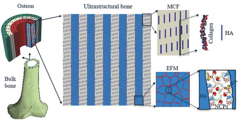
Among the diverse list of biological materials, bone is an exceptional tissue, which is light-weight to allow efficient body locomotion, while strong and damage-tolerant to manage physiological and impact loads to protect body’s vital organs [Citation15,Citation16]. Bone displays five hierarchical levels ranging from macro to nano length scales [Citation17]. At macroscale, long bones consist of a spongy portion called cancellous bone (usually at the ends of long bones) and a dense portion called cortical bone, the outer layer forming shaft of long bones (). At the mesoscale, basic building block of cortical bone is osteons, cylindrical structures about 100–200 microns in diameter with a central canal (Haversian canal) of approximately 30–40 microns in diameter. Osteon itself is made up of concentric few microns thick rings, called lamella. Lamella represents the hierarchical level containing most of the key ultrastructural features, namely Mineralized Collagen Fibril (MCF) and Extrafibrillar Matrix (EFM) [Citation18,Citation19]. MCF is mainly comprised of a soft organic material (type-I collagen) and hard hydroxyapatite (HA) mineral platelets that mostly reside in the gap regions of staggered collagen molecules. EFM consists of HA crystals bonded through a thin layer of Non-Collagenous Proteins (NCPs) [Citation20] which can be thought of as tough biological binders.
Figure 1. Hierarchical structure of bone spanning from macro to nanoscale. The shaft of long cortical bone is primarily made of cylindrical features called osteon. Osteon includes several concentric rings, each called a lamella. Inside a given lamella, ultrastructure of bone consists of alternating array of Mineralized Collagen Fibrils (MCF) and Extrafibrillar Matrix (EFM). MCF is made by a staggered arrangement of hydroxyapatite (HA) platelets mostly residing within the soft collagen matrix. EFM is comprised of HA crystals bonded by thin layers of Non-Collagenous Proteins (NCPs).
Design of bone-like materials by mimicking its osteonal feature [Citation21] or lamellar characteristic [Citation22] has yielded enhancement of materials toughness. To further exploit the superior design of bone, here we proposed a composite model inspired by ultrastructure of bone. Finite element (FE) model of the proposed composite was analyzed in tensile loading condition. Then, the bioinspired composite was compared against a conventional composite made with the same constituents and volume fractions of hard and soft phases. The differences in their mechanical properties and damage process were discussed.
Inspiration and design
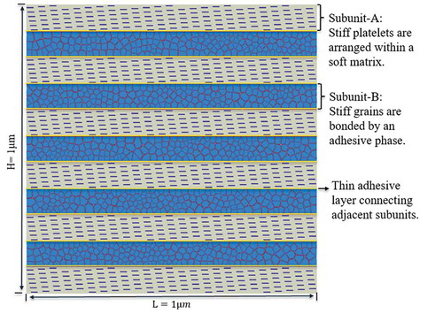
The proposed bioinspired material model () is a hybrid nanocomposite consisting of two subunits, i.e. subunit-A and subunit-B, to mimic the ‘mineralized collagen fibril’ and ‘extrafibrillar matrix’ of bone at ultrastructural level, respectively. In subunit-A, stiff (hard phase) platelets were embedded in a compliant matrix (soft phase), following a staggered arrangement. The properties of the hard and soft materials were selected to approximate those of hydroxyapatite mineral and type-I collagen fibrils in bone tissue, respectively. In subunit-B, randomly distributed stiff grains (hard phase) were bonded via a thin adhesive layer to mimic the ultrastructural arrangement of hydroxyapatite mineral and non-collagenous proteins in bone. The two subunits were alternatively placed along the longitudinal direction, with adhesive bonding between them.
Figure 2. The proposed material model is a hybrid composite inspired by ultrastructure of bone. It consists of an alternating parallel array of two basic subunits A and B connected together by a thin layer of adhesive phase. The subunits A and B represent the mineralized collagen fibril and extrafibrillar matrix of bone ultrastructure, respectively.
Finite element (FE) modeling
Geometry and mesh
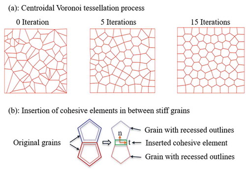
FE package ABAQUS (version 2016) was used to create the geometry and FE model of the composite. The shape and distribution of polygon-shaped grains in subunit-B were randomly generated using Centroidal Voronoi tessellation method [Citation23]. Briefly, first a set of n uniformly distributed random points (called seeds) were generated inside a bounded rectangular region in a two-dimensional space. Then, the rectangle was partitioned into n polygons (called Voronoi) such that the distance of any point inside a given polygon to the assigned seed inside that polygon was shorter than its distance to any other seeds. Then, in order to make the generated polygons more regular and without having short edges (to improve the quality of corresponding finite element mesh), an iterative approach was adopted. In each iteration, the geometrical centroid of polygons was selected as new set of seed points and the process of generating polygons was performed again ()). This iteration process ensured the shape and distribution of polygons to be more uniform. A big number of iterations was avoided as it would result in highly regular shaped polygons, which might not represent the reality. In this study, we used seven iterations. Finally, the Python script provided the information about each polygon along with their corresponding vertices and coordinates of each vertex. Another script was developed to use this information and create the geometry of the model in ABAQUS. Then, polygons were proportionally shrunk to create cohesive elements representing the adhesive phase in between stiff grains ()). Each subunit-B includes 200 grains with random shape and size. The subunit-A was created with hard platelets having a dimension of 5nm× 40nm embedded in the soft phase and being spaced apart by a 300 nm distance along the fibril direction.
Figure 3. (a) The process of Centroidal Voronoi tessellation to create the geometry of randomly shaped and distributed grains inside subunit-B; (b) The process of inserting cohesive elements representing adhesive phase in between stiff grains.
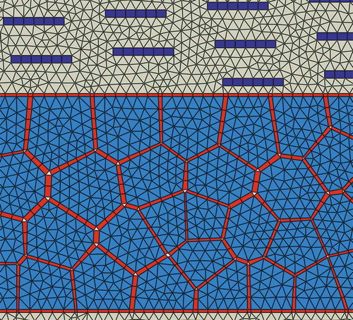
Subsequently, different layers of the created subunits were assembled alternatively with a thin adhesive layer of 2nm thick (same adhesive layer that was used to bind hard grains) in between any two adjacent subunits. Appropriate partitioning was automated in the Python script to ensure conforming and regular shaped elements at interfaces of adjacent subunits. This was necessary as the geometry of different layers of subunit-B were different from each other and partitioning points had to be obtained from the geometry of each subunit individually. Eventually, the final model included six subunit-A and five subunit-B and was meshed in ABAQUS. The volume fractions of the different constituents of the bioinspired composite were selected as follows: soft phase ~ 50vol%, stiff grains ~ 39vol%, stiff platelets ~ 6vol%, adhesive phase ~ 5vol%. Finite element mesh consisted of ~ 126,000 triangular elements (CPE3 from ABAQUS library), ~ 6,000 quadrilateral elements (CPE4R), and ~ 11,000 cohesive elements (COH2D4). CPE3 and CPE4R elements were used to mesh soft and stiff phases, whereas COH2D4 elements were used to model adhesive interfaces present in subunit-B and in between adjacent subunits. A zoom-in view of the finite element mesh is shown in .
Figure 4. A zoom-in view of mesh.
Cohesive element formulation
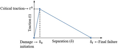
In this study, cohesive element available in ABAQUS library (labeled as COH2D4) was used to model the thin adhesive phase. Cohesive element is capable of capturing the damage initiation and evolution of the adhesive material. The behavior of such element is governed by defining a relation between cohesive traction and separation of the element. Here we adopted the bilinear traction-separation law as shown in . In this formulation, the cohesive traction () initially increases linearly with its respective separation (
), until it reaches to the critical strength of the interface (
). At this point, damage initiates and evolves following a linear damage evolution process, where cohesive traction gradually decreases to zero at final failure separation (
). The traction and separation can happen in both normal or shear direction. The area under traction-separation curve in normal and shear directions is equivalent to fracture energy in mode-I (
) and mode-II
, respectively.
Figure 5. A typical bilinear traction-separation law.
In this study, two-dimensional (2D) cohesive elements were used, for which the constitutive relation between traction and separation in initial stage (before damage initiation) is defined as:
Where ,
,
and
are the traction and separation components along normal and shear direction, respectively.
,
and
are the initial stiffness of the cohesive element relating the traction to the separation. Here,
was opted, considering an uncoupled relation between normal and shear direction before damage initiation. The quadratic traction damage initiation criterion was selected as the condition to specify the damage initiation point:
Here and
are critical tractions (interface strength) in normal and shear direction, respectively. The
if
and it equals 0 if
. This is because the compressive tractions are not allowed to contribute to damage initiation. Once the condition given in Eq. (2) is satisfied, the damage evolution phase starts. In the damage evolution phase, the tractions are calculated by Eq. (3):
Where D is the damage index ranging from 0–1 (1 meaning complete failure of the interface), and
are normal and shear tractions extracted from Eq. (1) corresponding to current values of separations. It is evident that no damage appears in pure compression. The damage index D is defined as:
Where we have equivalent separation and equivalent final separation
The effective traction is equivalent to
and the equivalent fracture energy is defined by a power law form as:
Where ,
,
,
, and
. The power law coefficient that controls the mode-mixity was selected as
Material properties
The soft phase was modeled as elastic-plastic material with strain-hardening behavior and the final failure strain is ~ 4% to approximate the properties of collagen in bone as reported in literature [Citation24]. The ductile-damage material model available in ABAQUS library was used to model the soft phase. The hard phase was modeled as an isotropic linear elastic material with limit stress of . The adhesive phase was defined using the aforementioned cohesive element approach. All material data used for defining the hard, soft and adhesive phases are given in and .
Table 1. Material parameters used for modeling soft and hard phases.
Table 2. Material parameters used for modeling the adhesive phase.
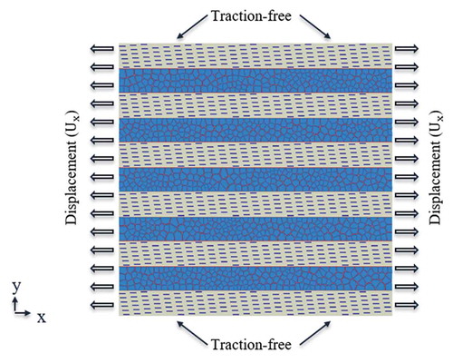
Simulation setup
Right and left edges of the model were subjected to displacement boundary conditions in x-direction, creating an equivalent tensile strain (). Top and bottom edges of the specimen were set as traction-free boundary condition. An explicit simulation step in ABAQUS was selected to solve the governing equations. Explicit method was selected to ensure converged solution especially when material softening and damage happen in cohesive elements. Increment time step was selected as , mass-scaling was activated during the simulation step to ensure that
is less than minimum stable time increment required for stability.
Figure 6. Boundary conditions for modeling the bioinspired composite.
FE simulations and analysis
First, the bioinspired composite model was studied to find the stress distribution, stress-strain relation, and damage progress at both bulk and the individual subunit levels. To construct the bulk stress-strain curve of the model, the average bulk stress was calculated through dividing sum of nodal reaction forces (The component in loading direction) by the area they were acting on. The average stress of subunits was obtained by weight-averaging the stress over all elements in the subunit. The applied strain to the model was measured as the applied displacement divided by the initial length of the model (. Next, the damage process and stress-strain relation of the bioinspired model was compared against those of a conventional composite.
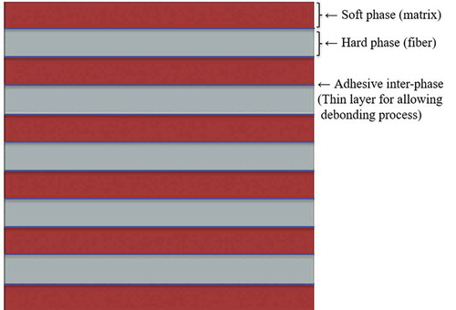
To evaluate the performance of the bioinspired composite, a FE-model of a conventional composite with same material (soft and hard phase) and volume fractions of the bioinspired composite was created (). A thin layer of adhesive phase was assumed between the hard phase and soft phase, in order to capture the debonding behavior between the two phases. The adhesive phase was modeled by cohesive elements. To model the breaking of hard fibers, zero-thickness cohesive elements were inserted in hard phase, aligned in the direction normal to fibers. These cohesive elements act as candidates for fracture sites in hard phase. The strength assigned to these cohesive elements was set as while the fracture energy was set at a small value (
), resulting in a brittle failure mode for fibers. The fiber strength was selected as
mainly because this was close to the maximum stress achieved in the hard phase when bioinspired composite was stretched all the way to final failure. The material data, specimen size, mesh, and boundary condition was consistent for the conventional bioinspired composite. The conventional composite was subjected to tensile deformation along the fibers direction.
Figure 7. The conventional composite model. Cohesive elements were embedded in fibers at vertical direction to model the fiber failure.
Results
Deformation and failure process of the bioinspired composite
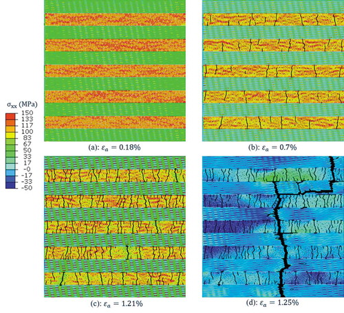
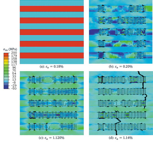
FE simulations captured the distribution and evolution of stress in the model. At initial stage of deformation ()), stress () was much higher in subunit-B than that in subunit-A. This suggests that that the adhesive phase efficiently transferred the load to the stiff grains, making subunit-B the prime load-bearing subunit in pre-yield deformation regime. Stress distribution in subunit-A was not uniform; stress appeared in the hard platelets was higher than that of the soft matrix. As the model was being stretched further, normal stress built up in the adhesive interface bonding the stiff grains, and met the critical strength of the adhesive phase. This resulted in gradual damage degradation of cohesive elements, which caused multiple cracks within subunit-B ()). The number of cracks kept increasing by further stretch of the model ()). At this post-yield deformation regime, overall stress level gradually decreased in subunit-B, whereas the hard platelets in subunit-A started to carry much higher stress compared to the other components in the composite. It was also noted that the post-yield stress distribution in subunit-B was rather inhomogeneous, with the lowest stress appearing in the neighborhood of the interfacial cracks. The extensive array of adhesive damage zones dissipated energy while the model was still able to endure more load, because subunit-A was un-cracked and able to hold the integrity of the composite. However, ultimately the stress in soft phase reached to its maximum strength and crack started to grow into the soft phase ()). Thereafter, crack extended and traveled across the whole width of the model and resulted in final failure of the composite.
Figure 8. Stress contour at different applied strains: (a) at pre-yield stage of deformation, subunit-B was major load-bearing subunit, experiencing high tensile stress; (b-c) in post-yield stage of deformation, damage started and evolved in adhesive phase, creating multiple cracks within subunit-B that gave rise to energy dissipation; (d) Stress in soft phase reached to its critical strength and crack propagated into soft matrix to form a final failure crack.
Stress-strain relation in the bioinspired composite
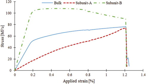
The average stress () versus applied strain was plotted for the bulk and individual subunits of the bioinspired composite (). The bulk stress-strain curve displayed initial linear response with modulus
up to the yielding at 50MPa. Before yielding, the averaged stress in subunit-B was significantly higher than that of subunit-A. Once the average stress in subunit-B reached the critical strength of the adhesive phase (
), yielding ensued in bulk stress-strain curve. After yielding, the bulk stress proceeded with a gradual increase with a much lower slope and reached the ultimate strength of 76 MPa at applied strain of
Thereafter, stress quickly dropped to zero at
. It was noted that concurrent with the increase in the bulk stress at post-yield region, the average stress of subunit-B decreased monotonically. This was due to damaging and cracking of adhesive phase in that subunit. On the other hand, the stress in subunit-A kept increasing constantly.
Figure 9. Stress-strain relation of the bulk composite and its basic subunits. At pre-yield stage of deformation, subunit-B was the primary load-bearing subunit. The composite showed an appreciable amount of post-yield deformation up to reaching to its ultimate strength. During the post yield deformation, stress kept relaxing in subunit-B, due to damage and cracking of the thin adhesive layers bonding the stiff grains. However, load was being gradually transferred to subunit-A such that stress kept increasing in subunit-A.
Deformation and failure process of the conventional composite
For the conventional composite, the stress distribution contours showed that initially the fibers carried most of the load ()), then they fractured at several locations instantaneously ()). After this first set of fiber failure, stress again kept increasing in both fiber and matrix ()). Several hot spots appeared in matrix due to the stress concentration arising from fiber cracking ()). Fiber matrix debonding was also observed, mostly at the crack tips, resulted in pull out of fiber pieces. Upon further stretch of the model, stress in soft phase reached the strength of soft phase material, thus resulted in crack extension into the soft phase. Eventually, the crack propagated and led to final failure of the model ()).
Figure 10. Stress distribution and damage process of the conventional composite model subjected to tensile loading along the fiber direction (x-direction).
The stress-strain relation for the conventional composite () reflected an initial linear deformation stage with modulus where stress reached to its maximum value
at
, which is close to the fiber fracture point shown in ). Afterward this drop, stress again gradually kept increasing to
at
, mostly because of contribution of the matrix and remaining parts of the fiber that were remained intact and obtained the load through the inter-phase material. Eventually at
stress quickly dropped to zero.
Figure 11. Stress-strain relation for the bioinspired and conventional composite model.
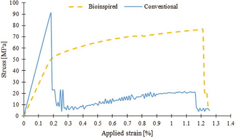
The mechanical properties obtained from stress-strain curves for both composites are given in . Toughness was measured as the total area under stress-strain curve. The results indicated that the toughness, strength and elastic modulus of the bioinspired composite was 312%, 83%, and 55% of that of the conventional composite, respectively.
Table 3. The mechanical properties of bioinspired and conventional composite.
Discussion and conclusions
In this work, we presented a new hybrid composite material by mimicking the ultrastructure of bone. The bioinspired composite was made of two basic subunits replicating the mineralized collagen fibrils (subunit-A) and extrafibrillar matrix (subunit-B) of bone. Subunit-A itself can be realized as a composite built by reinforcing a soft phase matrix, such as Poly(methyl methacrylate), with short fibers of a hard phase, such as hydroxyapatite (HA), arranged in a staggered manner. Subunit-B alone resembles a composite made of hard phase grains embedded in a compliant and ductile matrix (named adhesive phase). Beside from extrafibrillar matrix of bone, the structure of subunit-B is also similar to nacre from mollusk shells [Citation25], in which calcium carbonate tablets bind together in their interface via a thin layer of protein material. The hybrid composite was formed by alternating layers of subunit-A and subunit-B with an adhesive phase between them. This led to a composite with two hierarchies. At micron length scale, it was made of two structural features, i.e. subunit-A and subunit-B. At nanoscale, each of those structural features possesses their own internal structure such as staggered short fiber or thin adhesive layers.
The results of this study indicated that the bioinspired composite is a ductile, damage-tolerant material outperforming the conventional composite, even though both models are comprised of the same types and volume fractions of basic ingredients. Although the conventional composite appears to possess a higher stiffness relative to bioinspired composite, it is brittle and its strength drops in a sudden manner at very low strain levels. In contrast, the bioinspired composite exhibits an appreciable amount of plastic deformation with stable stress-strain response up to its ultimate strength (). The simulation results suggested that the bioinspired design was capable of replicating the main toughening mechanisms observed in bone at ultrastructural level. As the model was stretched, the thin adhesive phase connecting the hard grains transferred and distributed the load among hard grains. This gave the model its initial stiffness (). This value was smaller than what is expected from traditional rule of mixture. The reason for this discrepancy was that in bioinspired design the adhesive phase with low modulus (
) are present among the hard phase, thus reducing its equivalent stiffness. As the model was further stretched, interfacial damage gradually initiated in the adhesive phase, thus leading to yielding of bioinspired composite. Stress kept increasing after this yielding point. However, contrary to bioinspired composite, the stress in conventional composite dropped sharply after brittle failure of fibers start occurring. In the bioinspired design, multiple damage and cracks were formed after yielding throughout the model at the adhesive interface between the hard-phase grains, thus helped dissipating a large amount of energy. The similar damage pattern was observed in bone under tensile load, reminiscent of ‘diffuse damage’ mode and ‘dilatational bands’ reported in the literature [Citation26,Citation27]. Another mechanism is the crack-bridging role of subunit-A, which hinder further propagation and coalescence of the cracks formed in subunit-B, while allowing for interfacial damage to occur at the interface between the soft and hard phases within subunit-B. Indeed, such damaging mechanism helps keeping the structural integrity of the hybrid composite and allows for energy dissipation inside subunit-B, equivalent to the cooperative deformation of mineral and collagen phase observed in bone. More specifically, before yielding subunit-B carries the most part of load since its stiffness was much higher than that of subunit-A. However, after yielding the load is gradually transferred from subunit-B to subunit-A, making the two subunits share the load applied to the composite. As the results suggested, the bioinspired design yields a tough composite with potential promising applications in different fields [Citation28,Citation33].
One limitation of the current study is that the bioinspired and conventional composite models considered here are simplified 2D models of fiber-reinforced composites, which represent only a single lamina of laminate composites. Since the bioinspired design outperforms the conventional composite at lamina level (from toughness point of view), it is reasonable to assume that it will show the similar advantage (toughening) at laminate level as well.
Acknowledgments
This research was supported by a grant from National Science Foundation (CMMI-1538448), and a grant from the University of Texas at San Antonio, Office of the Vice President for Research. This work received computational support from UTSA’s HPC cluster Shamu, operated by the Office of Information Technology.
Disclosure statement
No potential conflict of interest was reported by the authors.
Additional information
Funding
References
- J.F.V. Vincent, Structural Biomaterials, Princeton, New Jersey: Princeton University Press, 2012.
- J.W.C. Dunlop and P. Fratzl, Biological composites, Annu. Rev. Mater. Res. 40 (2010), pp. 1–24. doi:10.1146/annurev-matsci-070909-104421.
- M.A. Meyers, P.-Y. Chen, A.Y.-M. Lin, and Y. Seki, Biological materials: Structure and mechanical properties, Prog. Mater. Sci. 53 (2008), pp. 1–206. doi:10.1016/j.pmatsci.2007.05.002.
- R.O. Ritchie, The conflicts between strength and toughness, Nat. Mater. 10 (2011), pp. 817–822. doi:10.1038/nmat3084.
- J.-Y. Rho, L. Kuhn-Spearing, and P. Zioupos, Mechanical properties and the hierarchical structure of bone, Med. Eng. Phys. 20 (1998), pp. 92–102. doi:10.1016/S1350-4533(98)00007-1.
- M.E. Launey, M.J. Buehler, and R.O. Ritchie, On the mechanistic origins of toughness in bone, Annu. Rev. Mater. Res. 40 (2010), pp. 25–53. doi:10.1146/annurev-matsci-070909-104427.
- G.E. Fantner, T. Hassenkam, J.H. Kindt, J.C. Weaver, H. Birkedal, L. Pechenik, J.A. Cutroni, G.A.G. Cidade, G.D. Stucky, D.E. Morse, and P.K. Hansma, Sacrificial bonds and hidden length dissipate energy as mineralized fibrils separate during bone fracture, Nat. Mater. 4 (2005), pp. 612–616. doi:10.1038/nmat1428.
- E. Hamed, Y. Lee, and I. Jasiuk, Multiscale modeling of elastic properties of cortical bone, Acta Mech. 213 (2010), pp. 131–154. doi:10.1007/s00707-010-0326-5.
- A.P. Jackson, J.F.V. Vincent, and R.M. Turner, The mechanical design of nacre, Proc. R. Soc. Lond. B Biol. Sci. 234 (1988), pp. 415–440. doi:10.1098/rspb.1988.0056.
- L. Lin, X. Wang, and X. Zeng, Computational modeling of interfacial behaviors in nanocomposite materials, Int. J. Solids Struct. 115–116 (2017), pp. 43–52. doi:10.1016/j.ijsolstr.2017.02.029.
- R.Z. Wang, Z. Suo, A.G. Evans, N. Yao, and I.A. Aksay, Deformation mechanisms in nacre, J. Mater. Res. 16 (2001), pp. 2485–2493. doi:10.1557/JMR.2001.0340.
- U.G.K. Wegst, H. Bai, E. Saiz, A.P. Tomsia, and R.O. Ritchie, Bioinspired structural materials, Nat. Mater. 14 (2015), pp. 23–36. doi:10.1038/nmat4089.
- P. Zhang, M.A. Heyne, and A.C. To, Biomimetic staggered composites with highly enhanced energy dissipation: Modeling, 3D printing, and testing, J. Mech. Phys. Solids. 83 (2015), pp. 285–300. doi:10.1016/j.jmps.2015.06.015.
- Z. Qin, B.G. Compton, J.A. Lewis, and M.J. Buehler, Structural optimization of 3D-printed synthetic spider webs for high strength, Nat. Commun. 6 (2015), pp. 7038. doi:10.1038/ncomms8038.
- J.D. Currey, Bones: Structure and Mechanics, Princeton, New Jersey: Princeton University Press, 2002.
- P. Ducheyne, K. Healy, D.W. Hutmacher, D.W. Grainger, and C.J. Kirkpatrick (eds.), Comprehensive Biomaterials II, 2nd ed., Elsevier, Amsterdam Boston Heidelberg, 2017.
- N. Reznikov, R. Shahar, and S. Weiner, Bone hierarchical structure in three dimensions, Acta Biomater. 10 (2014), pp. 3815–3826. doi:10.1016/j.actbio.2014.05.024.
- H.P. Schwarcz, E.A. McNally, and G.A. Botton, Dark-field transmission electron microscopy of cortical bone reveals details of extrafibrillar crystals, J Struct Biol.. 188 (2014), pp. 240–248. doi:10.1016/j.jsb.2014.08.006.
- M. Balooch, S. Habelitz, J.H. Kinney, S.J. Marshall, and G.W. Marshall, Mechanical properties of mineralized collagen fibrils as influenced by demineralization, J Struct Biol. 162 (2008), pp. 404–410. doi:10.1016/j.jsb.2007.10.011.
- L. Lin, J. Samuel, X. Zeng, and X. Wang, Contribution of extrafibrillar matrix to the mechanical behavior of bone using a novel cohesive finite element model, J. Mech. Behav. Biomed. Mater. 65 (2017), pp. 224–235. doi:10.1016/j.jmbbm.2016.08.027.
- F. Libonati, G.X. Gu, Z. Qin, L. Vergani, and M.J. Buehler, Bone-inspired materials by design: Toughness amplification observed using 3D printing and testing, Adv. Eng. Mater. 18 (2016), pp. 1354–1363. doi:10.1002/adem.v18.8.
- L.S. Dimas, G.H. Bratzel, I. Eylon, and M.J. Buehler, Tough composites inspired by mineralized natural materials: Computation, 3D printing, and testing, Adv. Funct. Mater. 23 (2013), pp. 4629–4638. doi:10.1002/adfm.v23.36.
- L. Lin, X. Wang, and X. Zeng, Geometrical modeling of cell division and cell remodeling based on voronoi tessellation method, CMES-comput, Model. Eng. Sci. 98 (2014), pp. 203–220.
- E. Gentleman, A.N. Lay, D.A. Dickerson, E.A. Nauman, G.A. Livesay, and K.C. Dee, Mechanical characterization of collagen fibers and scaffolds for tissue engineering, Biomaterials. 24 (2003), pp. 3805–3813.
- F. Barthelat and R. Rabiei, Toughness amplification in natural composites, J. Mech. Phys. Solids. 59 (2011), pp. 829–840.
- T.M. Boyce, D.P. Fyhrie, M.C. Glotkowski, E.L. Radin, and M.B. Schaffler, Damage type and strain mode associations in human compact bone bending fatigue, J. Orthop. Res. Off. Publ. Orthop. Res. Soc. 16 (1998), pp. 322–329.
- A.A. Poundarik, T. Diab, G.E. Sroga, A. Ural, A.L. Boskey, C.M. Gundberg, and D. Vashishth, Dilatational band formation in bone, Proc. Natl. Acad. Sci. 109 (2012), pp. 19178–19183.
- W. Wei and Q. Yang, A Finite Element Procedure for Analysis of Chemo-Mechanical Coupling Behavior of Hydrogels, Model. Eng. Sci. 112 (2016), pp. 033–058.
- M. Li, J. Zhang, N. Zhou, and Q. Zhang, Deformation and failure analysis of river levee induced by coal mining and its influence factor, CMES-Comput, Model. Eng. Sci. 113 (2017), pp. 183–194.
- H. Dong, Y. Nie, Z. Yang, Y. Zhang, and Y. Wu, Numerical accuracy analysis of asymptotic homogenization method and multiscale finite element method for periodic composite materials, CMES-comput, Model. Eng. Sci. 111 (2016), pp. 395–419.
- E. Hedayati and M. Vahedi, Numerical investigation of penetration in ceramic/aluminum targets using smoothed particle hydrodynamics method and presenting a modified analytical model, CMES-comput, Model. Eng. Sci. 113 (2017), pp. 295–323.
- M.C. Ray, L. Dong, and S.N. Atluri, Simple efficient smart finite elements for the analysis of smart composite beams - semantic scholar, CMES-comput, Model. Eng. Sci. 111 (2016), pp. 437–471.
- Y. Guo and J. Nairn, Simulation of dynamic 3D crack propagation within the material point method, CMES-comput, Model. Eng. Sci. 113 (2017), pp. 389–410.