
 ?Mathematical formulae have been encoded as MathML and are displayed in this HTML version using MathJax in order to improve their display. Uncheck the box to turn MathJax off. This feature requires Javascript. Click on a formula to zoom.
ABSTRACT
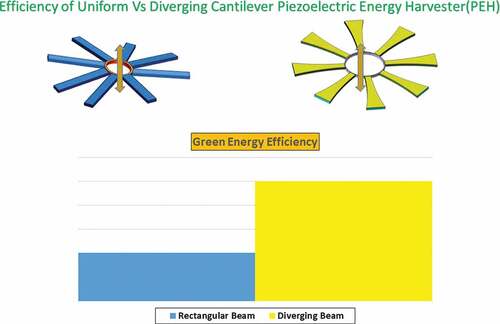
This paper presents the results of the performance of piezoelectric cantilever beams in relation to their size. The total produced power represents the main indicator of performance of a piezoelectric harvesting system while the area of the beams stays constant. Lightweight design is an important aspect in any industry, mainly in the aerospace. In this study, the effects of non-uniformity on the efficiency and power output are studied. Finite element method (FEM) with the application of superconvergent element (SCE) is adopted here to solve the equations. It is observed that the trapezoidal geometry (converging beam) provides a higher output power while the efficiency decreases. Moreover, in order to prove that the power enhancement is achievable while the amount of piezoelectric material consumed is constant the new configuration is proposed. In the configuration, an array of uniform beams connected in series is used instead of one single rectangular beam. The proposed setting generates an output power of 1.817 mW at a resonant frequency of 284.6 Hz when excited by an input acceleration of 1 g. The only challenge is the fundamental frequency difference which is met with the application of proof mass and thinner substrate and piezoelectric layers.
Abbreviations: : Generalized coordinates vector;
: The electrode area; A: The amplitude vector of generalized coordinates;
: Width;
: Initial width; C: Damping matrix;
: Capacitance of the one piezoelectric layer;
: Effective (equivalent) capacitance of the piezoelectric layers;
: Piezoelectric strain coefficient;
: The electric displacement;
: Young’s modulus;
: The electrical field along the thickness direction; F: Dynamic force vector;
: The translation part of base motion;
: Shear modulus;
: Piezoelectric layers’ thickness;
: Initial thickness of substrate layer;
: Imaginary number;
: Current output;
: Shear correction factor; K: Global stiffness matrix;
: Length of the beam;
: The length of one element; M: Global mass matrix;
: Polynomial’s degree;
: Matrices of shape functions (1×4 for one element);
: The input mechanical power;
: The output electrical power;
: Electric charge output; R: Displacement vectors of the generic point S (3×1);
: External load resistance;
: Velocity vector of the generic point S (3×1);
: Time;
: Kinetic energy;
: Axial displacement;
: Potential energy;
: Transversal displacements;
: Volume;
: The generated piezoelectric voltage
: Displacements on the middle-plane;
: Positions of a general point in the relative coordinates system;
: The amplitude of the effective displacement,
;
: The dielectric permittivity of piezoelectric layer at constant stress;
: The dielectric permittivity of piezoelectric layer at constant strain;
: The electromechanical coupling vector (3×1 for one element);
: The binding rotation of the cross section;
: Transverse shear strain;
: Axial strain;
: Axial stress;
: Transverse shear stress
: Shape functions of superconvergent element,
;
: Generalized coordinate elements,
;
: Mass density;
: The efficiency of harvesting;
: Excitation frequency;
: Constant of mass proportionality; Constant of stiffness proportionality;
: Damping ratio;
: Width taper ratio;
: Height taper ratio;
: The symbol of virtual work;
: The internal electrical energy;
: The non-conservative mechanical force; RD: Relative difference; PEHs: Piezoelectric energy harvesters; FEM: Finite element method; FRFs: Frequency response functions; DOF: Degree-of–freedom; MEMS: Micro-electromechanical system; MPGs: Micro-power generators; SCE: Superconvergent element;
: Piezoelectric layer properties;
: Substrate layer properties;
: Partial differentiation with respect to x;
: Partial differentiation with respect to t.
GRAPHICAL ABSTRACT
Introduction
Energy harvesting is a type of technology wherein the energy is captured from one or more external energy sources to be stored and eventually used for later applications. The subject has attracted considerable attention during the last decade due to the cost-effectiveness and efficiency of the system. The most important feature of power scavengers is their free energy sources which is collected from the wasted energy of the ambient surroundings. In comparison to the other common kinds of energy providers such as fuels, they are environmentally friendly and cost-effective. This rich source of energy is available in most of the industrial plants, machinery, vehicles of all types, and industrial machinery [Citation1–Citation3].
Nowadays, the energy scavenged from the harvesters have been known as an alternative source of energy. It has been considered as a support of the electric batteries supplying power for a wide variety of devices such as small wireless sensors and portable and wearable electronics owing to the noticeable advances in wireless technology [Citation4,Citation5]. In addition to the weight addition and the high cost of maintenance, short life of batteries represents their most important obstacle compared to the long working life of power scavengers. Although there is an opportunity to replace or recharge the batteries, this type of solution is inefficient and sometimes not feasible because of the poor access to their locations. Hence, local recharging from scavenging the free released energy represents a feasible alternative for solving this problem. As a result, power harvesters have been taken into consideration by many researchers as a renewable power source of portable or wireless devices in different areas [Citation6]. Among the three types of converters including electromagnetic, electrostatic, and piezoelectric, piezoelectric converters are advantageous structures with high electromechanical coupling [Citation7]. As an exclusive advantage, they do not need any external voltage source and are a promising choice for the micro-electromechanical systems (MEMS) application specially wireless sensor node [Citation8]. The amount of generated power from these useful structures strongly depends on the different factors including the applied load, the frequency of vibration, the geometric features, and the boundary conditions [Citation9].
Regarding the development of MEMS power generators, fixed or narrow operation frequency range and low power output are the most important challenges [Citation10]. To address the issue, researchers always have been attempting to reach to higher performance using different practical methods such as modification of shape, size, material properties, and damping [Citation11–Citation15]. There were also other researchers who adopted different strategies to broaden the frequency range and improve the power output [Citation16–Citation22]. Optimization of the active electrode area in order to maximize output is another important strategy illustrated by [Citation23–Citation25]. Another effective adopted method is the application of an array of piezoelectric cantilevers instead of one single beam [Citation26]. It not only covers a higher range of ambient frequencies, but also can help the researchers to improve the output power. To prove the efficiency of the strategy, Soliman et al. [Citation27] presented a new architecture for wideband vibration-based micro-power generators (MPGs) with higher bandwidth compared to a traditional MPG. Also, Liu et al. [Citation28] investigated a MEMS power generator array based on thick-film piezoelectric cantilever to improve both output power and frequency bandwidth. These cantilevers are tunable for the desired low frequencies in the range of 200–400 Hz. As an optimization method, a new architecture consisting of an array of trapezoidal cantilevers on a circular rim was proposed [Citation29]. They could increase the output power and decrease the natural frequency using the diverging beam and tip mass [Citation13,Citation30–Citation32]. The effectiveness of tapered beam configuration can also be seen in other researches [Citation11,Citation33–Citation35]. Changing the thickness of the substrate layer or mounting a tip mass are two practical methods which have been exploited to change the resonance frequency of the cantilever energy harvesters [Citation10]. Other studies were carried out to improve the output power and decrease the fundamental frequency through the application of a parallel or series array of piezoelectric energy harvesters (PEHs) [Citation26,Citation36]. Splitting the piezoelectric layer into smaller segments is another strategy which was implemented to change the resonant frequency of a cantilever energy harvester [Citation37]. In order to cover a wide range of excitation frequencies and attain higher output power, a piezoelectric generator was fabricated by multiple circular diaphragm array [Citation38]. They used four circular diaphragm piezoelectric harvesters with various tip masses which covered the resonance frequencies from 120 Hz to 225 Hz. Additionally, an AIN-based MEMS piezoelectric cantilever array including five piezoelectric cantilever beams and a single proof mass in series connection were presented to increase the output voltage and reduce the loss in a management circuit [Citation39]. Although by the application of series and parallel connections there is possibility to improve the desired electrical output, utilization of more piezoelectric material is unavoidable. As a matter of fact, mass of the piezoelectric part plays an important role in the microfabrication cost of the energy harvesters. In fact, although conventional piezoelectric materials including PZT and PVDF are useful, their fabrication process is time-consuming and expensive. More importantly, they are not environmentally friendly materials. Thus, there is a need to improve the efficiency and electrical output without changing the used amount of piezoelectric material. In this paper, the effects of the tapered structure is investigated on the efficiency and power output of PEHS with the scope to figure out which structure provides the maximum efficiency or power. The beam is modeled with the assumptions of Timoshenko beam theory but it can be easily switched to the Euler–Bernoulli beam with the application of superconvergent element (SCE). Secondly, enhancement power is met with the application of an array of cantilever beams although the same amount of piezoelectric layer is consumed. This new design leads to 15.64% substrate weight reduction, as well. In order to tune the fundamental frequency the thinner substrate and piezoelectric layers are applied. Overall it is shown by sizing a beam, modeled using the SCE model, it is possible to improve the power produced by the structure without alteration of the operation natural frequency of main system and total structure weight.
Tapered energy harvester
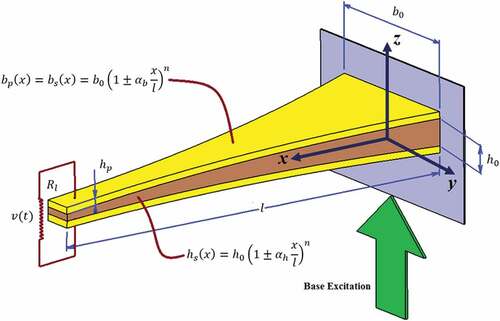
In this section, the theoretical model of the tapered energy harvester is presented. The cantilever beam has a non-uniform width, b(x), and height, h(x), varying according to the polynomial function, as shown in . It is assumed that perfect bonding is performed such that there is no slip between the piezoceramic layers and the substrate layer.
Figure 1. A 3D schematic model of piezoelectric-based cantilever energy harvester with non-uniform width and height.
Equations of motion for a tapered bimorph PEHs
By the assumption of a Timoshenko beam, the displacement of a generic point can be defined by
where ,
, and
are the displacements projected on the mid-plane,
is the rotation of the corresponding cross-section at point
and time
relative to the moving base, and
is the transverse translation coming from the base motion. Using the definition of Lagrange strain tensor and using the non-zero components of the flexible displacement, the normal and shear strains are obtained as
With the assumption of linear piezoelectric constitutive equations [Citation40], the calculated piezoelectric constitutive equations are summarized in EquationEquation 4(4)
(4) [Citation41].
where is the normal stress,
is the shear stress,
is the normal strain,
is the shear strain,
is the shear modulus,
is the elastic modulus,
is the electric displacement, d31 is the piezoelectric strain coefficient,
is the dielectric permittivity of the piezoelectric layer at constant stress and finally
and
are the shear correction factor and the applied electrical field, respectively.
The next step through the derivation of governing equations is the application of the Hamilton’s principle (EquationEquation 5(5)
(5) ).
where ,
,
and
are the virtual works of the total kinetic energy, the strain energy, the internal electrical energy and the non-conservative mechanical force, respectively.
The kinetic and strain energies of the entire structure are described using the following equations.
where and
are the tip mass and its associated moment of inertia. Other coefficients are also defined as follows
Additionally, the internal electrical energy in the piezoelectric layer can be calculated as follows
where is the internal capacitance of the piezoceramic defined by EquationEquation (11)
(11)
(11) :
where is the dielectric permittivity at constant strain and
is the electrode area.
In the above equations, dots and prime symbols identify derivatives with respect to time and space (i.e. x), respectively. The only non-conservative virtual work is owing to the electric charge output which is defined in EquationEquation (12)
(12)
(12)
To complete the modeling, the effects of damping should be taken into consideration. In this study, the proportional damping (Rayleigh damping) is applied [Citation42].
Discretization of equations using superconvergent element
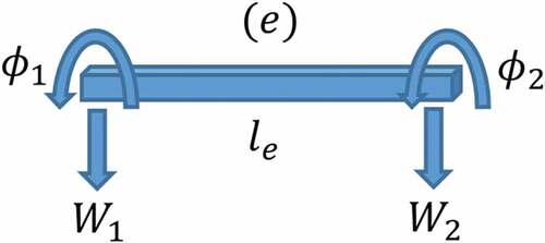
The final step is discretization of the coupled model. Finite element method (FEM) with the application of SCE is employed here. This type of element contains two nodes and four degrees-of-freedom (DOF) which include two DOF in the transverse direction and two DOF in the rotational direction (). The element provides the precise response with the minimum number of elements since the shape functions are derived by using static equilibrium (Appendix A). One of the most important advantages of this practical element is the simple transferring method. In fact, it is possible to switch readily from the Timoshenko to the Euler–Bernoulli by changing the value of one coefficient (). Hence, analysis based on both beam theories can be carried out without performing extra calculations [Citation43]. Using the calculated shape functions available in Appendix A, the displacement parameters in terms of the nodal displacements are represented in EquationEquation (13)
(13)
(13) .
Figure 2. Two-node finite element with four DOF.
where and
are the shape functions and
is the unknown generalized coordinates. By substitution of EquationEquation (13)
(13)
(13) into EquationEquation (5)
(5)
(5) and by performing integration by parts, the electromechanical coupling equations for a typical finite element result in EquationEquations (14)
(14)
(14) and (Equation15
(15)
(15) ). Addition of the Rayleigh damping accounting for the mechanical dissipative effects is the last stage of modeling (EquationEquation (16)
(16)
(16) ).
where and
are the constants of mass and stiffness proportionality. Terms
,
,
,
are, respectively, the mass matrix; the damping matrix; the elastic stiffness matrix; the electromechanical coupling matrix and the vector of dynamical forces corresponding to one element of the piezoelectric cantilever beam, and
is the equivalent capacitance (Appendix B).
Solution of the eletromechanical coupling equations
By the assumption of the input in the harmonic form and assembling the elements of the cantilever energy harvester the components of the forcing vector become:
The assembled steady-state forms of electromechanical coupling equations can be achieved as EquationEquations (18)(18)
(18) and (Equation19
(19)
(19) ) by the definition of the steady-state response and the voltage output. These two parameters are considered
and
, respectively.
After solving the above equations the complex voltage is obtained as
Expressions of power density and efficiency
To compare the performance of different systems and structures it is necessary to define one type of measurements. Regarding the PEHs, electrical output power extracted from the structure is one kind of calculation which has been widely used. Although this is a practical measurement, it cannot provide a precise and correct evaluation because the value strongly depends on the size, vibration environment and circuit conditions [Citation44]. In fact, the application of a larger beam can result in higher output power. For the comparison of two different configurations the mechanical input power is one important factor which should not be neglected. In this regard, there are other measurement parameters including the power density (output power divided by the piezoelectric layer volume) and efficiency which have been of primary interest. In this paper, both parameters are taken into consideration for the comparison target and their results are analyzed and compared.
Efficiency is a sufficient comparison factor indicating the amount of the input mechanical energy () which can be converted into the output electrical power (
) (EquationEquation (21)
(21)
(21) ).
where is the energy coming from the shaker which creates the excitation. Thus, the amount of input energy can be written as [Citation45]
By having the input and output energies, the harvesting efficiency is defined as
Results and discussion
Before parametric study of the energy harvester is carried out, there is a need to validate the numerical solution. To satisfy the requirement, the output voltage and fundamental frequency of uniform and non-uniform beams are firstly compared with those available in literature. After that, the influence of non-uniformity on both the power and efficiency are studied to figure out which configuration (converging or diverging beams) can result in the maximum desired measurement parameters. Finally, the application of an array of PEHs () instead of having one single cantilever energy harvester is proposed as the array has the capability to harvest more power.
In the first example, the convergence of the SCE is verified by considering a bimorph cantilever beam investigated by Erturk and Inman [Citation41] for both with and without the tip mass. The properties of the investigated bimorph piezoelectric beam which are connected in series are summarized in .
Table 1. Properties of the uniform bimorph piezoelectric cantilever beam.
To be able to compare the results, the short-circuit () and open-circuit (
) conditions are considered in agreement with the ones proposed in the open literature [Citation41]. The fundamental resonance frequency of the PEH based on the Timoshenko beam theory for two types of considerations are provided in –.
Table 2. Fundamental resonance frequency of piezoelectric energy harvester without tip mass.
Table 3. Fundamental resonance frequency of piezoelectric energy harvester with tip mass (0.239 g).
The excellent convergence rate of SCE is obvious from the results in which using only one SCE the difference between the experimental and theoretical values for both conditions is negligible (less than 0.5%). Hence, the represented SCE has a very good rate of convergence for the study of PEHs.
Figure 3. A 3D simulated structure of an array of diverging bimorph PEHs.

As the second part of validation, the output voltage of one non-uniform PEH is compared with the literature [Citation10]. They assumed that the width of the beam is varying exponentially through the length by . The properties of studied PEH are listed in . The output voltage for five different tapering parameters are calculated and provided in . The electrical resistance and damping ratio are taken 1000
and 1%, respectively.
Table 4. Properties of the tapered bimorph piezoelectric cantilever beam.
Table 5. Validation of piezoelectric energy harvester’s voltage for different tapering values.
It can be concluded again that SCE has a great rate of convergence so that with the application of only one SCE the relative error between the numerical and analytical results is less than 0.7%.
In the next example, the effects of tapering ratio on the power density and efficiency of the PEH is analyzed. The energy harvester has the same properties as described in the previous example. To optimize the system, the effects of tapering ratio () and the degree of polynomial function are investigated and depicted in –. The results show that by increasing the tapering ratio (application of diverging beam) the power output increases while the efficiency decreases. Obviously, increasing the content of piezoelectric material enables the increasing pattern of the output power. The input absorbed energy from the environment will yield more power at the cost of reduced efficiency for the diverging beams. In other words, for the diverging beam the amount of input absorbed energy is higher in comparison to converging structure, leading to smaller efficiency. Additionally, by the comparison of graphs associated with
and
illustrated in –, it is concluded that the effects of tapering ratio in width direction (
) yields more power output and higher efficiency. It is necessary to point out that the variation of efficiency and the power output are investigated here for the fixed value of load resistance providing small values. In order to maximize the parameters the value of external load resistance should be optimized as well [Citation41].
To study the influence of tapered beam on the performance, the variation of power FRF curves for both tapering parameters is shown separately in and . It can be found that the peak voltage of power increases dramatically by 2038% while the tapering ratio changes from to
. Although the power output escalates, the fundamental natural frequency decreases significantly. As the tapering parameter varies from 0.6 for diverging beam to −0.6 for converging beam, the resonance frequency reduces by 622% from 917.81 Hz to 147.58 Hz. Consequently, we get variation in frequency range and the peak of output power when
is changing but the changes are not as dramatic as the
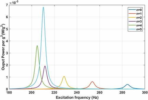
case. The degree of polynomial function is another determinant parameter for the output power as the influence is depicted in . The power output is increased by 1744.5% for tapered beam with n = 5 with respect to uniform beam for which
. The enhancement of electrical output is due to increasing the surface of the structure. In fact, since the piezoelectric layer is the part contributing to the generation of power output, increasing the polynomial degree results into the expansion of the surface of cantilever beam covered by the piezoelectric material and exposed to strain. This will be resulting in higher electrical output. Thus, the above analysis and investigation shows while the power output increases for the diverging beam the frequency reduces.
Figure 4. Power output variation versus polynomial degree under different tapering ratios in width direction ().
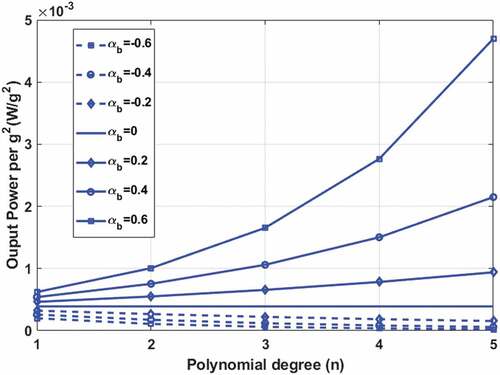
Figure 5. Power output variation versus polynomial degree under different tapering ratios in height direction ().
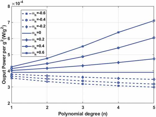
Figure 6. Efficiency variation versus polynomial degree under different tapering ratios in width direction ().
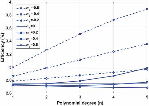
Figure 7. Efficiency variation versus polynomial degree under different tapering ratios in height direction ().
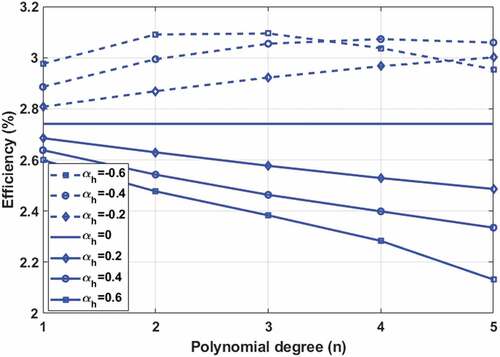
Figure 8. A power FRF curves for quintic tapered beam in width direction.
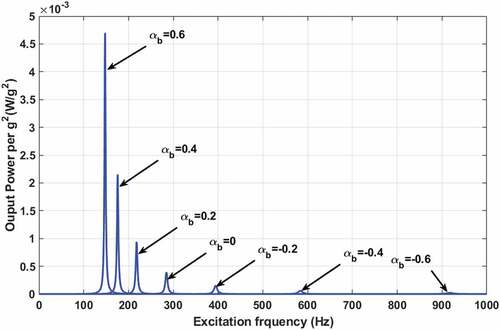
Figure 9. A power FRF curves for quintic tapered beam in height direction.
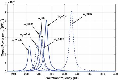
Figure 10. A power FRF curves for tapered beam () of different polynomial degrees.
In the next example, the amount of power output per volume of piezoelectric layers is investigated using the application of an array of PEHs instead of having one single beam. The properties of the PEHs are the same as in previous examples. Since the effects of sizing are important, the ratio of length over width of the beam is kept constant for comparison. Application of smaller beams will result in the increased fundamental frequency. This frequency difference for the beams with the smaller size should be surmounted since the target is maximization of output power without the change of operation frequency. Application of tip mass has been one of the simplest and most useful methods used to tune the frequency. Selection of an appropriate tip mass could change the mass of system to meet the desirable natural frequency. The tip mass attached to the tip of the cantilever PEH such that the center line of the cube is at the tip of the beam [Citation41]. The variation of power for different arrays of beams with the same volume is shown in and . By analyzing the results, it can be concluded that the application of smaller cantilever beams and tip masses (for the frequency tuning) provides the possibility to increase the power noticeably. Decreasing the size of the beams resulted in increasing the output power. For example, by the application of 25 beams connecting in series, the corresponding power increases by 958% with respect to that of the uniform beam although the operation frequency remains constant, around 284.6 Hz. Although the smaller size has an increasing effect on the power output, the amount of required tip mass for the beam with this small size is not feasible. In fact, this tiny beam cannot withstand the . Moreover, the addition of this amount of mass to the structure will result in escalating the total mass. Thus, the modification should be made to decrease the amount of required proof mass or even remove it entirely. To satisfy the requirement, application of thinner beam method is employed.
Reducing the thickness of piezoelectric and substrate layers is the desired method considered here. From it appears that increasing the tapering ratio not only results in the reduction of resonance frequency, but also amplification of the electrical power output. This kind of useful feature is used to remove the tip mass completely. The new structure consists of an array of tapered beams (). The thickness of the piezoelectric and substrate layers are considered to be the same, as well. In order to find a suitable value for the thickness, its effect on the natural frequency should be firstly analyzed. This analysis is necessary to figure out for which thickness one can reach the desired resonant frequency of 284.6 Hz. The effect of increasing thickness for the array of beams is shown in . The active/passive layer thickness is varied from 0.1 mm to 0.5 mm. As it was expected, the graphs show that there is a linear relationship between the frequency and the thickness. Hence, for every array of the beams with specific size, there is an optimal thickness value. The comparison of power FRFs per unit mass of piezoelectric layers between the original rectangular beam and the modified tapered beams is represented in . The results show that the new designed systems are capable of scavenging more power but the fundamental natural frequency is the same for all structures. The overlapping of the curves indicates that the analyzed configurations provide the same amount of power. The produced output power per unit mass is 88.32 mW/kg under 1.0 g which is 29.5% higher with respect to the one provided by a single uniform beam. Although the structure harvests more energy, there is still room to increase the output by the change of length-to-width ratio.
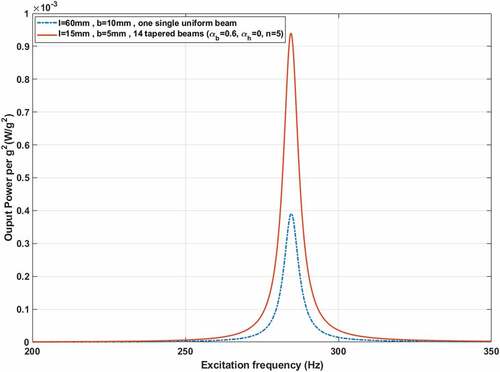
As the last step, the effects of ratio of the length over the width of the beam are investigated to find the optimum value. As is obvious from , decreasing the ratio can result in increasing the maximum output power of the system. By reducing the ratio from 12 to 3 there is a possibility to enhance the output power by 267%. It is noticeable the width at the free end of the beam is the limiting factor. In other words, the ratio should be a feasible value in order to achieve an acceptable structure. The comparison of power FRFs per mass of the piezoelectric material between the primary uniform beam and the new designed ones with different lengths over width ratios is calculated and represented in . As the completing part, a performance comparison between an array of 14 tapered bimorph cantilever beams with the geometry: and the primary uniform cantilever beam is analyzed and shown in . The curves reveal that the output power dramatically increases from 0.391 mW to 0.940 mW (140% more power). In this enhanced design, not only the amount of piezoelectric martial consumed is constant, but the mass of the substrate layer is reduced by 15.64%.
By and large, it has been shown that by the adoption of sizing analysis and application of an array of beams in series connection instead of one single beam one can noticeably improve the power output of the system. It should be pointed out that the amount of used active material and fundamental natural frequency remain constant for the comparison. To offset the tip mass concern, the thinner layers can be used but the acceptable amount of thickness reduction depends on the fabrication limitation and the stability of the structure. In other words, it is not possible to decrease the thickness more below the limit of buckling or to the level that the beam could wrinkle. Another practical way which can help in the tuning target is the application of substrate layer with lower modulus of elasticity resulting in lower natural frequencies. This is for further analysis which can be considered to achieve more power output with less amount of required tip mass. Paper-based piezoelectric structures are among the potential structures which can be used to satisfy the requirements [Citation46].
Figure 11. Comparison of power FRFs between one uniform beam and an array of multiple uniform beams.
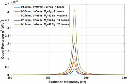
Figure 12. Comparison of power FRFs per piezoelectric mass between different beam sizes.
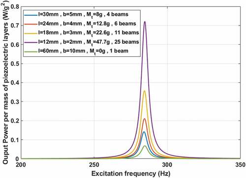
Figure 13. Fundamental frequency as a function of piezoelectric/substrate layer thickness ().
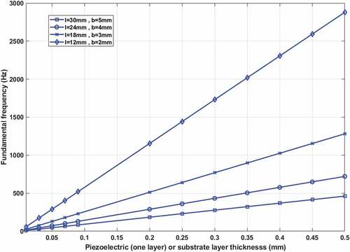
Figure 14. Comparison of power FRFs per piezoelectric mass between different beam sizes.
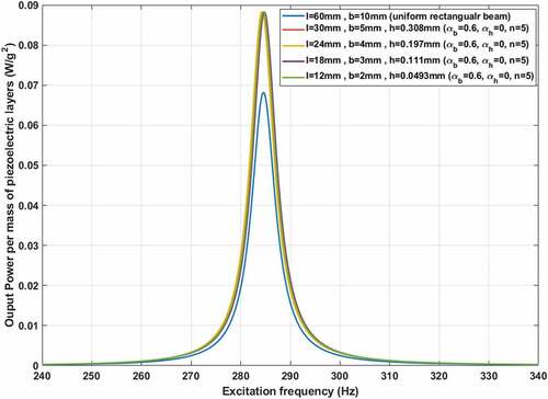
Figure 15. Comparison of maximum power output per piezoelectric mass between different beam ratios.
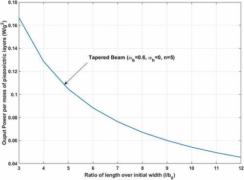
Figure 16. Comparison of power FRFs per piezoelectric mass between different length/width ratios.
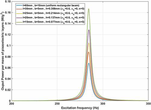
Figure 17. Comparison of power FRFs between the primary uniform beam and an array of tapered beams.
Conclusions
In this study, the effects of tapered beam on both the efficiency and the power output of PEHs were investigated. The influence of sizing on the amount of scavenged power was also studied and an enhanced system consisting of an array of uniform beams was proposed. For the analysis of the structure, the superconvergent beam was taken into consideration. To validate the accuracy of the element, the results available in the literature were compared. Application of this proposed element provided the great possibility of switching readily from the Timoshenko to the Euler–Bernoulli by changing the value of one coefficient ().
Analysis of the non-uniform beams showed that when the tapering ratio increases (diverging beam) the output power rises while the efficiency decreases, and vice versa. Expanding the degree of polynomial function also intensified the increasing/decreasing pattern. For example, changing the degree from to
for the tapered beam with the tapering properties
resulted in the power output increase by 1644.5%. The mentioned paradox for the trends of efficiency and power is originated from different amounts of input energy. It should be pointed out that changing the geometry of the beam (application of converging or diverging beam) changes the fundamental resonance frequency of the structure, as well. It is feasible to improve the objective target (efficiency or power) by tapering according to a polynomial function. It can be concluded that although application of diverging beam results in the power output enhancement it increases the weight which is an important subject in different industries such as aerospace. In order to save more material the sizing analysis and application of an array of beams was targeted as the second feasible concept.
In order to improve the power output with the same amount of material, a new system consisting of an array of tapered beams (diverging beams) was proposed. In the new architecture although the same amount of piezoelectric material was used the harvested electrical power output increased significantly by 140%. Additionally, the weight of substrate layer is reduced by 15.64% by the application of thinner substrate layer. The results showed that in order to increase the power output it is not always necessary to employ thicker piezoelectric layers. The power output strongly depends on the properties of the system, especially the external load resistance. For the design of the new system, the operation frequency (fundamental natural frequency) was kept constant. To tune the natural frequency of the smaller arrays of tapered beams to the original uniform beam, the thinner layers were employed. Therefore, the new proposed architecture could provide a solution for the challenging task of recharging the batteries in wireless sensor nodes.
Disclosure statement
No potential conflict of interest was reported by the authors.
Additional information
Funding
References
- Liu H, Zhong J, Lee C, et al. A comprehensive review on piezoelectric energy harvesting technology: materials, mechanisms, and applications. Appl Phys Rev. 2018;5(4):041306.
- Toprak A, Tigli O. Piezoelectric energy harvesting: state-of-the-art and challenges. Appl Phys Rev. 2014;1(3):031104.
- Yang Z, Zhou S, Zu J, et al. High-performance piezoelectric energy harvesters and their applications. Joule. 2018;2(4):642–697.
- Roundy S, Wright PK, Rabaey J. A study of low level vibrations as a power source for wireless sensor nodes. Comput Commun. 2003;26(11):1131–1144.
- Sodano HA, Inman DJ, Park G. A review of power harvesting from vibration using piezoelectric materials. Shock Vibr Dig. 2004;36(3):197–206.
- Kim HS, Kim JH, Kim J. A review of piezoelectric energy harvesting based on vibration. Int J Precis Eng Manuf. 2011;12(6):1129–1141.
- Wei C, Jing X. A comprehensive review on vibration energy harvesting: modelling and realization. Renew Sust Energ Rev. 2017;74:1–18.
- Shu YC, Lien I. Efficiency of energy conversion for a piezoelectric power harvesting system. J Micromech Microeng. 2006;16(11):2429.
- Dutoit NE, Wardle BL, Kim S-G. Design considerations for MEMS-scale piezoelectric mechanical vibration energy harvesters. Integr Ferroelectr. 2005;71(1):121–160.
- Salmani H. Rahimi GH and Hosseini Kordkheili SA. (2015) An exact analytical solution to exponentially tapered piezoelectric energy harvester. Shock and Vibration, 2015. https://doi.org/10.1155/2015/426876.
- Dietl JM, Garcia E. Beam shape optimization for power harvesting. J Intell Mater Syst Struct. 2010;21(6):633–646.
- Guizzetti M, Ferrari V, Marioli D, et al.. Thickness optimization of a piezoelectric converter for energy harvesting. Proceedings of the COMSOL Conference. Milan, Italy. 2009.
- Jia Y, Seshia AA. Power optimization by mass tuning for MEMS piezoelectric cantilever vibration energy harvesting. J Microelectromech Syst. 2015;25(1):108–117.
- Palosaari J, Leinonen M, Juuti J, et al. The effects of substrate layer thickness on piezoelectric vibration energy harvesting with a bimorph type cantilever. Mech Syst Signal Process. 2018;106:114–118.
- Stewart M, Weaver PM, Cain M. Charge redistribution in piezoelectric energy harvesters. Appl Phys Lett. 2012;100(7):073901.
- Erturk A, Hoffmann J, Inman DJ. A piezomagnetoelastic structure for broadband vibration energy harvesting. Appl Phys Lett. 2009;94(25):254102.
- Hu Y, Yi Z, Dong X, et al. High power density energy harvester with non-uniform cantilever structure due to high average strain distribution. Energy. 2019;169:294–304.
- Li N, Yi Z, Ma Y, et al. Direct powering a real cardiac pacemaker by natural energy of a heartbeat. ACS Nano. 2019;13(3):2822–2830.
- Liu H, Lee C, Kobayashi T, et al. Piezoelectric MEMS-based wideband energy harvesting systems using a frequency-up-conversion cantilever stopper. Sens Actuators A. 2012;186:242–248.
- Shi Q, Wang T, Kobayashi T, et al. Investigation of geometric design in piezoelectric microelectromechanical systems diaphragms for ultrasonic energy harvesting. Appl Phys Lett. 2016;108(19):193902.
- Yeo HG, Xue T, Roundy S, et al. Strongly (001) oriented bimorph PZT film on metal foils grown by rf‐sputtering for wrist‐worn piezoelectric energy harvesters. Adv Funct Mater. 2018;28(36):1801327.
- Yi Z, Yang B, Li G, et al. High performance bimorph piezoelectric MEMS harvester via bulk PZT thick films on thin beryllium-bronze substrate. Appl Phys Lett. 2017;111(1):013902.
- Du S, Jia Y, Chen ST, et al. A new electrode design method in piezoelectric vibration energy harvesters to maximize output power. Sens Actuators A. 2017;263:693–701.
- Du S, Jia Y, Seshia A. Maximizing output power in a cantilevered piezoelectric vibration energy harvester by electrode design. J Phys: Conf Ser. 2015; Boston, USA: IOP Publishing, 012114.
- Hajheidari P, Stiharu I, Bhatt R. Power output enhancement of piezoelectric energy harvesters using electrode coverage optimization. ICAST2019: 30th International Conference on Adaptive Structures and Technologies. Montreal, QC, Canada, 165–166;2019.
- Lin H, Wu P, Lien I, et al. Analysis of an array of piezoelectric energy harvesters connected in series. Smart Mater Struct. 2013;22(9):094026.
- Soliman M, Abdel-Rahman E, El-Saadany E, et al. A wideband vibration-based energy harvester. J Micromech Microeng. 2008;18(11):115021.
- Liu JQ, Fang HB, Xu ZY, et al. A MEMS-based piezoelectric power generator array for vibration energy harvesting. Microelectronics J. 2008;39(5):802–806.
- Nisanth A, Suja K, Seena V. Design and simulation of MEMS AlN piezoelectric vibration energy harvester array for improved power density. 2018 IEEE Sensors. IEEE, 1–4; 2018.
- Andosca R, McDonald TG, Genova V, et al. Experimental and theoretical studies on MEMS piezoelectric vibrational energy harvesters with mass loading. Sens Actuators A. 2012;178:76–87.
- Bowen C, Kim H, Weaver P, et al. Piezoelectric and ferroelectric materials and structures for energy harvesting applications. Energy Environ. Sci. 2014;7(1):25–44.
- Kim JE, Kim YY. Analysis of piezoelectric energy harvesters of a moderate aspect ratio with a distributed tip mass. J vibr acoust. 2011;133(4):041010.
- Beeby SP, Tudor MJ, White N. Energy harvesting vibration sources for microsystems applications. Meas SciTechnol. 2006;17(12):R175.
- Glynne-Jones P, Beeby SP, White NM. Towards a piezoelectric vibration-powered microgenerator. IEE Proc-Sci, Meas Technol. 2001;148(2):68–72.
- Mehraeen S, Jagannathan S, Corzine KA. Energy harvesting from vibration with alternate scavenging circuitry and tapered cantilever beam. IEEE Trans Ind Electron. 2009;57(3):820–830.
- Liu H, Quan C, Tay CJ, et al. A MEMS-based piezoelectric cantilever patterned with PZT thin film array for harvesting energy from low frequency vibrations. Phys Procedia. 2011;19:129–133.
- Ahmed SM, Eladawy MI, Salem MS, et al.. Controlling the frequency response of a cantilever-based energy harvesters using split piezoelectric elements. 2018 International Japan-Africa Conference on Electronics, Communications and Computations (JAC-ECC). IEEE, 139–142; Alexandria, Egypt. 2018.
- Xiao Z, Yang T, Dong Y, et al. Energy harvester array using piezoelectric circular diaphragm for broadband vibration. Appl Phys Lett. 2014;104(22):223904.
- Zhao X, Shang Z, Luo G, et al. A vibration energy harvester using AlN piezoelectric cantilever array. Microelectron Eng. 2015;142:47–51.
- Leo DJ. Engineering analysis of smart material systems. Hoboken, NJ: John Wiley & Sons; 2007.
- Erturk A, Inman DJ. Piezoelectric energy harvesting. Chichester, UK: John Wiley & Sons; 2011.
- Meirovitch L. Fundamentals of vibrations. Illinois, USA: Waveland Press; 2010.
- Reddy JN. Energy principles and variational methods in applied mechanics. Chichester, USA: John Wiley & Sons; 2017.
- Kim M, Dugundji J, Wardle BL. Efficiency of piezoelectric mechanical vibration energy harvesting. Smart Mater Struct. 2015;24(5):055006.
- Shafer MW, Garcia E. The power and efficiency limits of piezoelectric energy harvesting. J vibr acoust. 2014;136(2):021007
- Kim JH, Ko HU. Zinc oxide-cellulose nanocomposite and preparation method thereof. USA: Google Patents; 2017.
AppendiesAppendix A. Shape functions of SCE
Lagrange linear shape functions
Cubic shape functions
Quadratic shape functions
where
where is the length of a typical element of the beam. In the previous shape functions, if
(or in other words
→ ∞ and
→ ∞, i.e. the assumption of no-shear-deformation theory), shape functions corresponding to the Euler–Bernoulli beam are obtained and the interpolating functions are reduced to cubic and quadratic Hermitian polynomials.