
 ?Mathematical formulae have been encoded as MathML and are displayed in this HTML version using MathJax in order to improve their display. Uncheck the box to turn MathJax off. This feature requires Javascript. Click on a formula to zoom.
ABSTRACT
Tactile sensors have been used for haptic perception in intelligent robotics, smart prosthetics, and human-machine interface. The development of multifunctional tactile sensor remains a challenge and limit its application in flexible electronics and devices. We propose a liquid metal based tactile sensor for both temperature and force sensing which is made by 3D printing. The structural design and working principle of liquid metal based tactile sensor are firstly described. A digital light processing-based printing process is developed to print two kinds of photosensitive resins with different hardness, and used to fabricate the tactile sensor. A Wheatstone bridge circuit is designed for decoupling the temperature and forces from the measured output voltages. Characterization tests show that the tactile sensor has relatively high force sensing sensitivity of 0.29 N-1, and temperature sensing sensitivities are 0.55% °C−1 at 20 ~ 50 °C and 0.21% °C−1 at 50 ~ 80 °C, respectively. Then, the fabricated tactile sensor is mounted onto hand finger to measure the contact force and temperature during grasping. Results show that the 3D printed tactile sensor has excellent flexibility and durability and can accurately measure the temperature and contact forces, which demonstrate its potential in robotic manipulation applications.
Graphical Abstract
Introduction
Flexible tactile sensors are playing an essential role in intelligent robotics [Citation1,Citation2], smart prosthetics [Citation3], human–machine interface [Citation4,Citation5], and Internet of Things (IoTs) [Citation6]. Inspired by human skin, several types of wearable and implantable electronic devices have been widely used in health monitoring [Citation7], such as the detection of electrocardiogram (ECG) signals [Citation8], pulse vibration [Citation9], and body temperature [Citation10]. Researches on tactile sensors have been focused on haptic perception such as pressure [Citation11], temperature [Citation12], slippage [Citation13], and sometimes a combination of multiple physics [Citation14], as these are necessary for human body and intelligent robotics to perceive in dexterous manipulations. Thus, tactile sensors usually need to have good deformability and stability, high sensitivity, multifunctional sensing abilities.
Traditional designed tactile sensors may be too rigid to fit the irregular surface of body skin or robotic hand, which will reduce the accuracy for haptic sensing. It is necessary to develop a tactile sensor with high flexibility and ductility [Citation15,Citation16]. In past decade, the structural design and manufacturing process to make flexible tactile sensors have achieved a great progress. Most of tactile sensors are usually designed sensitive to one kind of haptic information sensing, thus cannot be used for multifunctional haptic perception. In order to perceive more comprehensive tactile information, many researchers have proposed multifunctional tactile sensors using simple structure or multifunctional sensing materials. For example, Wang et al. [Citation8] have realized the direct writing of laser-induced graphene (LIG) on a Kevlar textile in air, which can be used to detect the ECG signal and NO2. Wang et al. [Citation14] have proposed a flexible tactile sensor based on silk-nanofiber-derived carbon fiber membranes (SilkCFM) that can be used to detect strain and temperature simultaneously. Therefore, develop a flexible tactile sensor with the ability to sense multifunctional tactile information is of great significance.
The sensitive material’s selection will greatly affect the sensing performances of the tactile sensor [Citation17]. Carbon materials (carbon nanotubes [Citation18], graphene [Citation19,Citation20], and natural-biomaterial-derived carbon [Citation21]), silver nanoparticles (AgNPs) [Citation22], liquid metals [Citation23], and hydrogels [Citation24] have been utilized for the structural design of tactile sensors. Liquid metal can be worked in liquid state at room temperature with both high electrical conductivity and deformability, which could improve the durability and stability of the tactile sensor for long-term usage [Citation25,Citation26]. Eutectic gallium–indium (EGaIn) and gallium–indium–tin (galinstan) are two commonly used liquid metals, galinstan liquid metal has generally low melting point (~19°C), high surface tension (~718 × 10−3 N·m−1), high electrical conductively (~3.46 × 10⁶ S·m−1), and thermal conductivity (~16.5 W·m−1·K−1) [Citation27–29]. Thus, galinstan liquid metal would be a promising sensitive material for the design of flexible tactile sensors and utilized in this study for the development of multifunctional tactile sensor.
For liquid metal-based tactile sensor, it is necessary to select a suitable process to fabricate the microfluidic channels to pattern the liquid metals. Currently, there are three commonly used patterning methods for liquid metals, including mask deposition [Citation30], injection into elastomeric microchannels [Citation31], and direct writing/printing [Citation32]. For instance, Guo et al. [Citation33] presented a method by using a patterned stainless steel mask and rolling brush to print Ni-EGaIn liquid metal on ecoflex substrate for the development of wearable and wireless healthcare electronics. Mohammed et al. [Citation34] proposed an automated multimode printing process for the fabrication of flexible electronics, includes extrusion printing of elastomer layers, spray printing of liquid metal slurry, and mechanical sintering of slurry particles. Previously, we utilized polydimethylsiloxane (PDMS) as elastomer substrate to fabricate tactile sensor with embedded fingerprint-shaped microfluidic channels, in which galinstan liquid metal was injected [Citation35]. The fingerprint-shaped channels are fabricated by using a pre-designed mold, the PDMS mixture during the fabrication process needs to be heated and cured, which resulting in a long period for the fabrication of tactile sensor. Digital light processing (DLP)-based printing process has been utilized for the printing of microfluidic channels for lab-on-chip device [Citation36], thus it would be a promising method for the fabrication of liquid metal-based tactile sensors. Currently, most of DLP-based printing processes merely use single photosensitive resin to fabricate the sensor, its sensing performance is hard to be improved. In order to improve the manufacturing efficiency and sensing performance of tactile sensor, multi-material DLP-based printing method and process still need to be investigated.
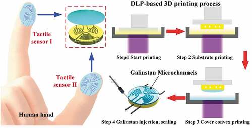
In this study, we develop a liquid metal-based tactile sensor for both temperature and contact force sensing through a two-step DLP printing process. The structural design and working principle of this tactile sensor are described, a Wheatstone bridge circuit is designed for decoupling the force and temperature signals. Two kinds of photosensitive resins with different hardness are prepared and used to print the base microfluidic channels and above convex structure for the printing of tactile sensor, and then galinstan liquid metal is injected into microfluidic channels to act as the sensing element. This is followed by the fabrication procedure to print the tactile sensor and its sensing performances characterization tests. Finally, the printed tactile sensor is mounted onto hand finger to measure both contact force and temperature during grasping applications. The results demonstrated the multifunctional sensing abilities of the developed liquid metal-based tactile sensor and verify its potential in wearable applications.
Design of liquid metal based tactile sensor
Schematic view of the structural design of the proposed tactile sensor is illustrated in ), the sensors are designed to be worn on hand index and thumb fingers. The tactile sensor is mainly consisted of two layers ()): round-shaped substrate with three sets of microfluidic channels where liquid metal embedded and function as the sensing elements, top domed-shaped convex layer with thickness decreases gradually from center to periphery. To fit hand fingertip, the overall diameter of the tactile sensor is set as 20 mm, three sets of microfluidic channels are arranged into fingerprint shape. Two sets of channels are located symmetrically in the central of substrate, another set of channels is located on the periphery region. The cross-section of each channel is 0.5 mm in height and 0.6 mm in bottom width.
Figure 1. (a) Schematic view of flexible tactile sensor worn on hand index and thumb fingers; (b) two-layered structure of the sensor and fingerprint-patterned microfluidic channels with embedded galinstan liquid metal; (c) temperature and contact force sensing principles
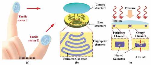
When external force is applied, it can be decomposed into a normal force F1 perpendicular to the surface, a tangential force F2 along the circumference, and a tangential force F3 along the radius direction. The force F1 will converge to the center and cause significant effects on the central microfluidic channels, while F2 and F3 have little effects since the radian of the convex structure. Besides, the center of convex structure has the highest height, the contact force will firstly act on the central part of the convex surface during most grasping process. Thus, the convex structure can efficiently concentrate the force to the region of two central microfluidic channels, and the cross-sectional area of microfluidic channel will be decreased. Since the volume and length of the liquid metal channels are not changed, the compressed Galinstan will be forced into the region away from the applied force and causes a little swelling of the microchannels. When compared with the part that shrinks, the swelled part has less influence on the resistance due to the increasing magnitude of the cross-section is less obvious. Thus, the concentrated force will lead to a significant resistance changes of liquid metal due to the decreases of cross-section area of microchannel. Compared with the central microchannels, the cross-sectional area of the microchannel in periphery region will changed much less under the same applied force as in ), the corresponding resistance change will also be smaller. Thus, the induced resistance changes caused by central two microchannels with liquid metal can be used for external force sensing.
As for temperature sensing, the resistances of liquid metal in both central and peripheral regions will be changed when temperature changed. Since these three sets of microchannels have the same geometry, the resistance changes caused by temperature variation will be ideally the same. Thus, the temperature sensing can be achieved by directly measuring the resistance changes of the peripheral microchannel with embedded liquid metal.
Experimental setup and procedure
Photosensitive resin preparation
Generally, natural or synthetic biopolymers are utilized as the substrate to endow the flexible electronics with mechanical robustness and good biocompatibility [Citation37]. Because the tactile sensor will be fabricated by DLP-based printing, the photosensitive material is selected and its preparation process will be important. To improve the flexibility, the substrate material is selected with low Young’s modulus and good deformability. As for top cover layer, a stiffer material with relatively high Young’s modulus is selected, which can concentrate external force to the sensing region and in turn enhance the sensitivity. Therefore, a multi-material DLP-based printing method needs to be developed for the printing of substrate and top cover layers with different Young’s modulus.
Here, the SP-RF0900 (SprintRay Inc.) and Ebecryl 110 (Allnex Co., Ltd.) photosensitive resins served as prepolymer and diluter are selected. The SP-RF0900 material is mainly consisted of aliphatic acrylate and polyurethane acrylate, the cured material has low stiffness and good resilience. The primary element of Ebecryl 110 is oxyethylphenol acrylate with low viscosity, it can be used to adjust the viscosity and hardness of prepolymer and photocuring reaction speed [Citation38]. The TPO-L is utilized as photo-initiator to initiate polymerization and cross-linking reactions of the prepolymer and diluent [Citation39]. Sudan I is used as stain, it has high absorbance under 405 nm wavelength light and can effectively reduce the over-curing during the printing procedure.
To prepare the printing materials, a series of photosensitive resin materials with different mass ratios of prepolymer and diluent were formulated, and printing tests were carried out. When the mass ratio of SP-RF0900 and Ebecryl 110 is 1:3, and TPO-L and Sudan I account for 2% and 0.1% of the total mass, the formulated photosensitive resin has good flexibility, and can be used as the substrate material for the tactile sensor. While adding the same proportion of TPO-L and Sudan I to SP-RF0900 without Ebecryl 110, the formulated material has higher hardness and can be used to fabricate the cover convex layer of the sensor.
3D printing of tactile sensor
A DLP-based printing system is setup and used to print substrate microfluidic channels and cover convex layer of the tactile sensor. Before printing, we first built the 3D geometry model of tactile sensor and subsequently imported this model into an open-source 3D printing software, in which the printing parameters were set and the model was sliced into a series of mask sequence. A thin layer of PDMS (Sylgard 184, Dow Corning Co., Ltd.) with the mixing ratio of base resin and curing agent at 10:1 and curved by heating at 60°C was coated onto the bottom surface of prepolymer vessel for anti-adhesion treatment [Citation40]. For the designed liquid metal based tactile sensor, the printing process and procedure are illustrated as shown in . The printing process can be mainly divided into four steps.
Figure 2. Fabrication process of the tactile sensor: (a) start printing; (b) printing the substrate layer with microfluidic channels; (c) printing the cover convex structure; (d) galinstan injection and sealing
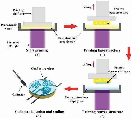
Step 1 – Photosensitive resins preparation: The photosensitive resin materials for substrate and cover layers are separately prepared according to pre-determined compositions, SP-RF0900, Ebecryl 110, TPO-L and Sudan I were mixed in proportion. Then, both two mixed materials were blended and degassed in a planetary mixer (AR100, Thinky Corporation) for 10 minutes until there were no obvious liquid layer or powders.
Step 2 – Substrate layer printing: After pouring the substrate photosensitive resin into the vessel ()), turn on the ultraviolet (UV) light source and activate 3D printing platform to start printing, the UV light is projected onto the bottom of prepolymer vessel. The printing material irradiated by UV light will be cured and adhered to the printing platform. As shown in ), it will rise layer by layer with the printing platform until the substrate layer with microfluidic channels was completed printed. Then, the residual resin material on the surface of printed part was gently removed to prevent over-curing and blocking of the substrate microfluidic channels in next step of printing.
Step 3 – Cover convex layer printing: The photosensitive resin material for printing the convex structure was firstly poured into the vessel, and turned on the UV light and activate the printing platform to print the convex layer of tactile sensor. Under UV light exposure, the cover layer and bottom substrate layer will be curved together, as shown in ).
Step 4 – Galinstan injection and sealing: The printed sensor was carefully peeled off from the printing platform, as shown in ). Then, it was placed in a beaker containing ethanol solution and put into an ultrasonic cleaning machine for 15 min to remove the residual photosensitive resins. After that, the sensor was placed on a heating platform and heated up to 50°C for 20 min, it can ensure that the ethanol in the microfluidic channels was fully volatilized. Then, the galinstan liquid metal (Ga:In:Sn = 62:22:16 wt%, AlfaAesar, Inc.) was slowly injected into the microchannels in the tactile sensor using a syringe, as shown in ). For sealing and encapsulation, the outlets of the wires were evenly coated with a layer of silicone rubber (SR, GD401). Finally, the sensor was heated up to 80°C for 2 hours to ensure a permanent sealing.
Figure 3. (a) Photograph of the printed tactile sensor; (b) final fabricated tactile sensor after sealing; (c) schematic view of the sensing circuit for temperature and force sensing
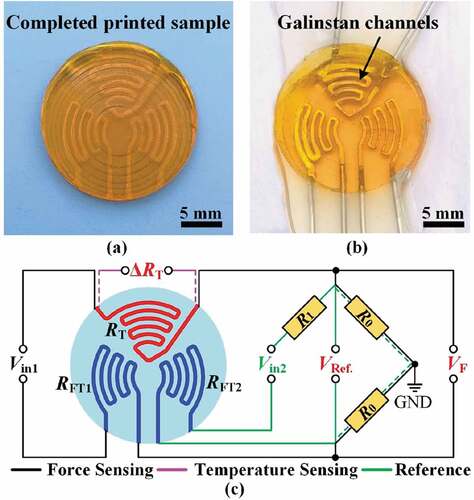
The final fabricated tactile sensor is shown in ), we can clearly see the boundary of the microchannels with galinstan liquid metal inside, the substrate and cover convex layers are closely bonded together. The initial resistance of each resistor formed by galinstan liquid metal is measured as about 101 mΩ, and the sensing region of the tactile sensor has a diameter of 20 mm with thickness of 1.0 mm. In the utilized soft photosensitive resin, the tactile sensor has generally good flexibility.
Characterization of 3D printed tactile sensor
For the printed tactile sensor, its sensing performances for force and temperature sensing need to be characterized first. Typically, the decoupling of temperature-induced resistance change from the measured output signals would be critical for accurate force sensing. For the designed tactile sensor, two sets of channels with embedded galinstan liquid metal in central region are sensitive to both external force and temperature stimuli, and the other channel with liquid metal on periphery region is mainly sensitive to temperature changes. A Wheatstone bridge circuit is designed to decouple the force and temperature signals, the resistors in center (RFT1, RFT2) and peripheral regions (RT) are connected into an equivalent circuit for force and temperature sensing, respectively. We utilized our testing platform [Citation31] to conduct the characterization tests, the tactile sensor was fixed on a heating platform that can provide changeable temperature, a plastic loading probe with a diameter of 15 mm was used to apply force to the sensor. The applied forces can be recorded by a commercial three-axis load cell (Interface 3A120) with resolution of 0.01 N and measurement range of 0–50 N. The loading probe combined with the load cell were attached to a z-axis linear stage (Zolix AKSM25A-65CCZ). The displacement and movement speed of the stage and loading probe can be accurately programmed to apply static and dynamic forces to the sensor.
For force sensing characterization, we switch on the input voltage of Vin1, the RFT1, RT and other two reference resistors can form a Wheatstone bridge, as shown in ). Since the resistance of R0 is much larger than RFT1 and RT, the initial stare of output voltage VF can be written as in EEquationquation (2(2-2)
(2-2) –Equation1
(2-1)
(2-1) ), where A can be regarded as constant. When the tactile sensor is subjected to temperature fluctuations, both RT and RFT1 will generate resistance changes of ΔRT′ and ΔRFT1′, which are almost identical to each other because the same shape of microfluid channels and sensing liquid metal. When the sensor was applied by an external force, both RT and RFT1 will generate relative resistance changes of ΔRT′′ and ΔRFT1′′, but the former one can be neglected due to the oval-shaped protrusion. Thus, the changed output voltage VF′ and the relative output voltage change ΔVF/VF can be written as in EEquationquation (2
(2-2)
(2-2) –Equation2
(2-2)
(2-2) ) and (Equation2
(2-2)
(2-2) –Equation3
(2-3)
(2-3) ), respectively. We can see that output result is only related to the applied force, thus the force and temperature signals can be successfully decoupled. When measuring the reference signals, we switch on the input voltage of Vin2. The resistance of the reference resistor R1 is almost the same as RT, which is used to form another Wheatstone bridge. As the same as the force sensing circuit, the relative change of the output voltage can be calculated by EEquationquation (2
(2-2)
(2-2) –Equation4
(2-4)
(2-4) ), which serves as a reference to see the effectiveness of the decouple process.
The voltage applied across the bridge input terminals (Vin1, Vin2) was offered by an external DC power supply (Keysight, E3643A, U.S.A.), the induced output voltages of the circuit (VF, VRef.) were recorded by a digital multimeter (Keysight, 34465A, U.S.A.). The sensitivity of force sensing is defined as SF = (ΔVF/VF)/F, where ΔVF and VF are the relative change and initial value of the output voltage from the circuit for force sensing, respectively, and F is the applied force.
For temperature sensing, we placed the sensor on the heating platform and attached a thermocouple of the multi-channel temperature measuring instrument (Anbai, AT4708, China) to its surface to monitor the temperature changes. The induced resistance changes (ΔRT) were measured using a multi-channel resistance tester (Anbai AT5130, China). The sensitivity of temperature sensing is defined as ST = (ΔR/R0)/T, where ΔR is the resistance change caused by temperature, R0 is the initial resistance and T is the applied temperature. After characterization, the cyclic loading tests were conducted, including loading force tests with different magnitude or frequencies and repetitions of the cyclic force and temperature tests.
Human hand grasping applications
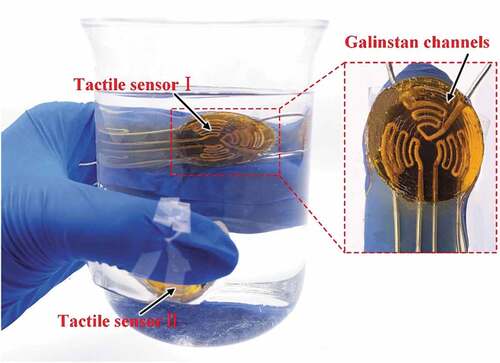
To verify the performances of the tactile sensor in practical application, human hand wearing and grasping tests were performed. As shown in , two tactile sensors labeled as Sensor I and Sensor II were attached onto hand index and thumb fingers, respectively. They were used to grasp three beakers of water with different temperatures. In each grasping test, both gentle and tight grasping were performed. For force sensing, we connect the corresponding resistors (RT, RFT1) to a Wheatstone bridge equivalent circuit and the output voltages (VF) were recorded by a digital multimeter (Keysight, 34465A, U.S.A.). As for temperature sensing, we connect the resistor (RT) to a multi-channel resistance tester (Anbai AT5130, China) for resistance changes monitoring, and record the real-time temperature of the water with a multi-channel temperature measuring instrument (Anbai, AT4708, China).
Figure 4. Photograph of the tactile sensors worn on fingertips for force and temperature sensing when grasp a beaker of water
Results and discussion
Characterization results of tactile sensor
The characterization results of the tactile sensor for force and temperature sensing are shown in . As the applied forces increased consecutively from 0 to 10 N under various temperatures from 20°C to 60°C, the measured output voltages (VF) are plotted as in ). We can see that the output voltages under three groups of temperatures increased and changed approximately linearly. Since the Wheatstone bridge can’t completely eliminate the temperature induced errors, the voltage measured under 40°C and 60°C has a little fluctuation, but the discrepancy of the measured output voltages induced by temperature variation is less than 8.4%, thus the temperature effects in force sensing can be nearly negligible. Using the linear least square fitting method, we fitted the data measured under temperature of 20°C, the force sensing sensitivity of the sensor is calculated as SF = 0.29 N−1, which is higher than some liquid metal based tactile sensors that have been reported [Citation10,Citation27,Citation41]. The fitted curve value R2 = 0.989, which indicate that the fitted curve has a good linearity. Besides, the detection range of the force measured linearly is about 0.2–10 N (~ 0.6–31 kPa), which actually covers most of situations for the robotic or human hand to manipulate objects.
Figure 5. Calibration results of the tactile sensor: (a) force sensing range from 0 to 10 N and (b) temperature sensing range from 20°C to 80°C
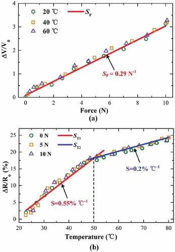
To ensure the validity of the tactile sensor for temperature sensing, the developed sensor was heated from 20°C to 80°C under forces of 0, 5 and 10 N, respectively. Since the tactile sensor is designed for robotic or human hand wearing application, this detection range of temperature is adequate for most manipulation process. As plotted in ), the relative resistance changes (ΔR/R0) increased simultaneously with the increasing of temperature. The calculated temperature sensing sensitivities (fitted without force applied) have two values: high sensitivity ST1 = 0.55%°C−1 from 20°C to 50°C, and low sensitivity ST2 = 0.2%°C−1 from 50°C to 80°C. Both the fitted curve values, R2 = 0.998, indicate that the fitted curve has generally good linearity. Since the convex structure can’t completely eliminate effects of applied force on temperature sensing, the resistance measured under external force seems a little biased, but the relative errors are less than 6.4%, which indicates that the temperature sensing is independent from the force variation due to our structural design of tactile sensor and Wheatstone bridge circuit.
The sensing performance of the tactile sensor was further investigated and results were provided in )–(d). Firstly, different forces of 3.0, 6.0, and 7.5 N at loading frequency of 0.03 Hz were applied to the tactile sensor in sequence, and the induced relative resistance changes (ΔR/R0) were measured and plotted as in ). We can see that the amplitude of ΔR/R0 increased synchronously with the loading force, and the relative resistance changes of the tactile sensor were approximately 13.6%, 26.5%, and 33.4% at different loading stages, respectively. When applied by the same loading force, the maximum values of ΔR/R0 were almost unchanged, and the ΔR/R0 behaved nearly stable in unloading state, which indicates that the 3D printed tactile sensor has relatively good stability and dynamic response under cyclic loading forces with different magnitude. Secondly, we applied forces of 3.0 N at frequencies of 0.013, 0.05, and 0.08 Hz to the tactile sensor, and the ΔR/R0 are shown in ). We can see that the maximum ΔR/R0 were almost unchanged at a value of approximately 13.8%, which indicates that the tactile sensor is also stable under loading forces with varied frequencies.
Figure 6. Sensing performance of the tactile sensor: (a) resistance change under different loading forces; (b) resistance change under different loading frequencies; (c) 200 cyclic loading and unloading tests; (d) cyclic heating and cooling tests
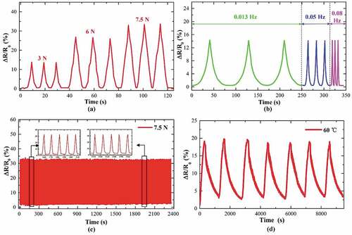
Subsequently, to further validate the repeatability and durability of the tactile sensor, a long-term multiple cyclic test was implemented using a loading force of 7.5 N with frequency of 0.08 Hz. A total of 200 cycles of loading and unloading tests lasted for about 2,400 s were conducted. As shown in ), the maximum and minimum values of the relative resistance changes (ΔR/R0) were stable during the cyclic loading and unloading tests and the fluctuations were almost neglected, which indicated that the tactile sensor has good repeatability and durability for long-term cyclic applications. Finally, cyclic heating and cooling tests were also conducted to verify the temperature sensing performance of the tactile sensor. The tactile sensor was heated from room temperature to 60°C, then it was cooled down to about 28°C; this test was repeated 7 times and lasted for about 9,500s. As shown in ), the relative resistance changes (ΔR/R0) of the tactile sensor changed simultaneously with the temperature, and the maximum value for each cycle maintained almost the same, which also indicated that the developed tactile sensor has generally good repeatability for temperature sensing. However, due to the large size of tactile sensor and intrinsic hysteresis of the cured photosensitive resins, it takes a relatively longer time for the tactile sensor to rapidly respond to external stimulus. To develop a tactile sensor with fast response and recovery time using DLP-based 3D printing method still needs further studies.
Hand grasping force and temperature sensing
After characterization of the tactile sensor, it was used to measure the contact force and temperature during hand grasping applications. Firstly, two tactile sensors (Sensor I and Sensor II) are worn on the index and thumb fingers, respectively. We can see that the developed tactile sensor has generally good flexibility, and fitted well to hand fingertips. Then, water of 150 ml at 30°C, 45°C, and 60°C are poured into three beakers, respectively. The whole grasping process can be divided into following steps: Step I – Fingers grasp the beaker containing water at 30°C gently and then release. Step II – Fingers grasp the same beaker tightly and then release. Step III – Fingers grasp the beaker containing water at 45°C gently and then release. Step IV – Fingers grasp the same beaker tightly and then release. Step V – Fingers grasp the beaker containing water at 60°C gently and then release. Step VI – Fingers grasp the same beaker tightly and then release. During the whole grasping process, the contact forces and temperatures of Sensors I and II are recorded.
The contact forces generated between tactile sensor and the grasped beaker are plotted in ). Since the three beakers contain nearly the same volume of water, the force signal detected by Sensor I on index finger have the similar value of 5.77, 5.43, and 5.55 N, respectively, during the gentle grasping procedure (Steps I, III, and V). And the forces recorded by Sensor II on the thumb show the same phenomenon, which have the value of approximately 5.64, 5.20, and 5.49 N. Similarly, during the tight grasping procedure (Steps II, IV, and VI), the forces acquired by two sensors increase as the grasping forces applied are larger. The force values recorded by Sensor I are 8.10, 8.04, and 8.06 N, and Sensor II shows the similar results of 7.98, 7.93, and 7.75 N. Generally, the forces detected by Sensor I on index finger were slightly greater than that of Sensor II on the thumb, which may be caused by the variation of hand finger motion during different grasping steps. We can see that when fingers apply nearly the same force to beakers of water with different temperatures, the measured contact forces fluctuated slightly, which demonstrated that the effects of temperature on contact force sensing can be effectively suppressed.
Figure 7. The measured results during hand grasping: (a) the measured forces and (b) temperature curves of Sensor I and Sensor II on index and thumb fingers
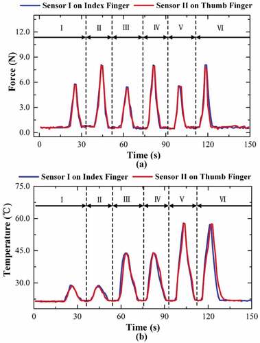
Further, the temperatures measured by tactile sensor during the grasping process are carefully analyzed, and the results are plotted in ). When grasping the beaker of water at nearly 30°C (Steps I and II), temperatures measured by Sensor I on index finger show values of 28.9°C and 28.8°C during gentle and tight grasping, respectively, while Sensor II on thumb finger measure the temperatures of about 28.5°C and 28.2°C. It can be seen that the temperatures acquired by Sensors I and II have nearly the same value, further the temperature fluctuations during gentle and tight grasping can be neglected. In addition, when grasping the beakers of water at 45°C (Steps III and IV) and 60°C (Steps V and VI), the measured temperatures show a similar result, which can be approximately 44.0°C and 57.8°C, respectively. All the measured temperatures by both two sensors are slightly lower than the expected temperature of water, which can be mainly attributed to the heat conduction loss as described in our previous work [Citation31]. We can see that the measured temperatures show a nearly synchronous change with the varied six grasping steps as previous described, but it still has a little asynchrony with the force sensing signals. That is because the temperature signal has a slower response time than that of force signals, and it takes a relatively long time for the temperature to react to the stimulus in real time. Thus, the measured temperature shows a relatively larger hysteresis. Overall, the measured temperatures by the tactile sensor were very close to the actual temperature, and the fluctuations caused by the applied forces can be neglected during temperature sensing applications.
From the above grasping results, it is verified that our 3D printed tactile sensor based on liquid metal can be used for independent temperature and contact force sensing during hand grasping applications, also the printed tactile sensor shows excellent flexibility, promising repeatability and durability. Furthermore, through the analysis of the acquired force and temperature, the hand grasping motion and grasping steps can be easily recognized, which highlights the potential applications of our flexible tactile sensor for human body movements identification, robotic manipulation, and so on.
Conclusion
In summary, we proposed a liquid metal based tactile sensor for both temperature and contact force sensing through the printing of DLP-based 3D printing method. The tactile sensor was composed of two layers with varied stiffness, both substrate fingerprint patterned microfluidic channels and cover convex structures’ design can improve the sensing performance. A two-step DLP-based printing method and process are developed to print the tactile sensor with good deformability and flexibility. Using the Wheatstone bridge circuit, the force and temperature sensing signals can be decoupled and measured independently. Calibration tests showed that the tactile sensor has high force sensing sensitivity of 0.29 N−1, and temperature sensing sensitivities have two values: 0.55%°C−1 for 20 ~ 50°C and 0.2%°C−1 for 50 ~ 80°C. Human hand grasping experiments demonstrated that the printed tactile sensor can accurately measure the contact force and temperature, further the grasping steps and movements can be easily identified, which indicated that our developed tactile sensor would have potential applications in flexible electronics for human–machine interactions, robotic manipulation, and healthcare monitoring. For further work, the DLP-based printing method to print large-area tactile sensor will be investigated. The proposed liquid metal based tactile sensor will be integrated into wearable electronics for robotic hand manipulation applications.
Acknowledgments
The authors acknowledge the funding support from Zhejiang Provincial Funds for Distinguished Young Scientists of China (LR19E050001), Fund for Creative Research Groups of National Natural Science Foundation of China (51821093), and Open Fund Project of Zhejiang Laboratory (2019MC0AB02).
Disclosure statement
No potential conflict of interest was reported by the author(s).
Additional information
Funding
References
- Carrico JD, Tyler T, Leang KK. A comprehensive review of select smart polymeric and gel actuators for soft mechatronics and robotics applications: fundamentals, freeform fabrication, and motion control, International. J Smart Nano Mat. 2018;8: 144–213.
- Luo S, Bimbo J, Dahiya R, et al. Robotic tactile perception of object properties: a review. Mechatronics. 2017;48:54–67.
- Abd MA, Al-Saidi M, Lin M, et al. Surface Feature Recognition and Grasped Object Slip Prevention With a Liquid Metal Tactile Sensor for a Prosthetic Hand. 2020 8th IEEE RAS/EMBS International Conference for Biomedical Robotics and Biomechatronics (BioRob). 2020; 1174–1179.
- Zhu P, Wang Y, Wang Y, et al. Flexible 3D architectured piezo/thermoelectric bimodal tactile sensor array for E‐skin application. Adv Energy Mater. 2020;10(39):2001945–2001952.
- Lu W, Yu P, Jian M, et al. Molybdenum disulfide nanosheets aligned vertically on carbonized silk fabric as smart textile for wearable pressure-sensing and energy devices. ACS Appl Mater Interfaces. 2020;12(10):11825–11832.
- An BW, Heo S, Ji S, et al. Transparent and flexible fingerprint sensor array with multiplexed detection of tactile pressure and skin temperature. Nat Commun. 2018;9(1):2458–2467.
- Li S, Zhang Y, Wang Y, et al. Physical sensors for skin-inspired electronics. InfoMat. 2020;2(1):184–211.
- Wang H, Wang H, Wang Y, et al. Laser writing of janus graphene/kevlar textile for intelligent protective clothing. ACS Nano. 2020;14(3):3219–3226.
- Lu T, Markvicka EJ, Jin Y, et al. Soft-matter printed circuit board with UV laser micropatterning. ACS Applied Mat Interfaces. 2017;9(26):22055–22062.
- Gao Y, Ota H, Schaler EW, et al. Wearable microfluidic diaphragm pressure sensor for health and tactile touch monitoring. Adv Mater. 2017;29(39):1701985–1701988.
- Kou H, Zhang L, Tan Q, et al. Wireless wide-range pressure sensor based on graphene/PDMS sponge for tactile monitoring. Sci Rep. 2019;9(1):3916–3922.
- Rao J, Chen Z, Zhao D, et al. Tactile electronic skin to simultaneously detect and distinguish between temperature and pressure based on a triboelectric nanogenerator. Nano Energy. 2020;75:1–9.
- Wang Y, Wu X, Mei D, et al. Flexible tactile sensor array for distributed tactile sensing and slip detection in robotic hand grasping. Sens Actuators A. 2019;297:1–13.
- Wang C, Xia K, Zhang M, et al. An all-silk-derived dual-mode e-skin for simultaneous temperature–pressure detection. ACS Appl Mater Interfaces. 2017;9(45):39484–39492.
- Dahiya RS, Metta G, Valle M, et al. Tactile sensing—from humans to humanoids. IEEE Trans Rob. 2010;26(1):1–20.
- Xi KL, Wang YC, Mei DQ, et al., A flexible tactile sensor array based on pressure conductive rubber for three-axis force and slip detection, 2015 IEEE/ASME International Conference on Advanced Intelligent Mechatronics (AIM) . 2015;476–481.
- Wang YC, Wu X, Mei DQ, et al. Flexible tactile sensor array for distributed tactile sensing and slip detection in robotic hand grasping. Sensors and Actuators A: Physical . 2017;29:111512.
- Oh J, Yang JC, Kim JO, et al. Pressure insensitive strain sensor with facile solution-based process for tactile sensing applications. ACS Nano. 2018;12:7546–7553.
- Basu J, Basu JK, Bhattacharyya TK. The evolution of graphene-based electronic devices. Int J Smart Nano Mat. 2010;1:201–223.
- Xia K, Wang C, Jian M, et al. CVD growth of fingerprint-like patterned 3D graphene film for an ultrasensitive pressure sensor. Nano Res. 2017;11:1124–1134.
- Wang C, Xia K, Wang H, et al. Advanced Carbon for Flexible and Wearable Electronics. Adv Mater. 2019;31:e1801072.
- Cao K, Yang H, Gao L, et al. In situ mechanical characterization of silver nanowire/graphene hybrids films for flexible electronics. Int J Smart Nano Mat. 2020;11:265–276.
- Park S, Mondal K, Treadway RM 3rd, et al. Silicones for stretchable and durable soft devices: beyond sylgard-184. ACS Appl Mat Interfaces. 2018;10:11261–11268.
- Zhang C, Deng H, Xie Y, et al. Stimulus responsive 3D assembly for spatially resolved bifunctional sensors. Small. 2019;15:e1904224.
- Zhu S, So J-H, Mays R, et al. Ultrastretchable fibers with metallic conductivity using a liquid metal alloy core. Adv Funct Mater. 2013;23:2308–2314.
- Park J, Wang S, Li M, et al. Three-dimensional nanonetworks for giant stretchability in dielectrics and conductors. Nat Commun. 2012;3:916–923.
- Shin H-S, Ryu J, Majidi C, et al. Enhanced performance of microfluidic soft pressure sensors with embedded solid microspheres. J Micromech Microeng. 2016;26:025011.
- Wong RDP, Posner JD, Santos VJ. Flexible microfluidic normal force sensor skin for tactile feedback. Sensors Actuators a-Phys. 2012;179:62–69.
- White EL, Case JC, Kramer RK. Multi-mode strain and curvature sensors for soft robotic applications. Sensors Actuators a-Phys. 2017;253:188–197.
- Kim M-G, Alrowais H, Pavlidis S, et al. Size-scalable and high-density liquid-metal-based soft electronic passive components and circuits using soft lithography. Adv Funct Mater. 2017;27:1–11.
- Ota H, Emaminejad S, Gao Y, et al. Application of 3D printing for smart objects with embedded electronic sensors and systems. Adv Mater Technol. 2016;1:1–8.
- Zheng Y, He ZZ, Yang J, et al. Personal electronics printing via tapping mode composite liquid metal ink delivery and adhesion mechanism. Sci Rep. 2014;4:1–8.
- Guo R, Wang X, Chang H, et al. Ni-gain amalgams enabled rapid and customizable fabrication of wearable and wireless healthcare electronics. Adv Eng Mater. 2018;20:1–9.
- Mohammed MG, Kramer R. All-printed flexible and stretchable electronics. Adv Mater. 2017;29:1604965–1604967.
- Wang YC, Lu YT, Mei DQ, et al. Liquid metal-based wearable tactile sensor for both temperature and contact force sensing. IEEE Sens J. 2021;21:1694–1703.
- He Y, Wu Y, Fu J-Z, et al. Developments of 3D printing microfluidics and applications in chemistry and biology: a review. Electroanalysis. 2016;28:1658–1678.
- Jian M, Zhang Y, Liu Z. Natural biopolymers for flexible sensing and energy devices, Chinese. J Polym Sci. 2020;38:459–490.
- Uzcategui AC, Muralidharan A, Ferguson VL, et al. Understanding and improving mechanical properties in 3D printed parts using a dual-cure acrylate-based resin for stereolithography. Adv Eng Mater. 2018;20:1800876.
- Placone JK, Engler AJ. Recent advances in extrusion-based 3D printing for biomedical applications. Adv Healthcare Mat 7. 2018;7(8): 1701161.
- Tumbleston JR, Shirvanyants D, Ermoshkin N, et al. Continuous liquid interface production of 3D objects. Science. 2015;347:1349–1352.
- Yeo JC, Yu KJ, Loh KP, et al. Triple-state liquid-based microfluidic tactile sensor with high flexibility, durability, and sensitivity. ACS Sens. 2016;1:543–551.