
 ?Mathematical formulae have been encoded as MathML and are displayed in this HTML version using MathJax in order to improve their display. Uncheck the box to turn MathJax off. This feature requires Javascript. Click on a formula to zoom.
ABSTRACT
Ionic polymer-metal composites (IPMCs) are typical smart materials that are commonly used in bionic applications, including soft robots, bionic flapping aircraft, and bionic fish. However, their low output force seriously limits device performance. Stacking of multiple IPMC actuators to improve the overall performance of soft actuators is a strategy that is used in practical applications. Under the energy dissipation condition in the IPMC stacking structure, if each single IPMC in the structure has high power density, the structure will produce excellent performance with high efficiency that can greatly promote wider application of IPMC actuators. To meet this requirement, a method for fabrication process integration with multiple optimized factors was used to obtain IPMC materials in this paper. Carbon nanotube (CNT) doping, isopropyl alcohol-assisted plating, and hot pressing with a mesoscopic structural mold were selected as typical optimization methods for process integration and were initially investigated separately to determine the optimal process parameters. By combining the best process parameters in an integrated process, the IPMC treated by isopropyl alcohol-assisted plating and CNT doping process (No. AC7) showed excellent actuation performance and high work density (~9.71/12.36 gf, ~14.93/31.89 kJ/m3 under 3/4 VDC). The enhanced performance meets the requirements for practical bionic applications.
Graphical abstract
1. Introduction
Ionic polymer-metal composites (IPMCs) are smart bionic materials with advantages that include flexibility, large-scale deformation, low driving voltages, and noiseless performance [Citation1,Citation2]. IPMCs are used as artificial muscles because of their muscle-like actuation behavior. As shown in ), most IPMC actuators generate no more than 1% strain and 1 MPa of stress; their volume work density is then less than 10 kJ/m3, whereas the work density of natural muscle is approximately 8–40 kJ/m3 with strain of 20%–40% [Citation3]. Because of their swing deformation form, IPMCs are regarded as ideal flexible actuators for use in the field of bionic machines, e.g. in inchworms, bionic flapping aircraft, and bionic fish. Over the last twenty years, many research groups with interests in IPMC bionic soft robots have emerged [Citation4–8]. It is now comparatively easy to realize soft robots and flexible devices based on IPMC bending deformation. However, these device applications are small and slow, and are usually driven using one or more IPMC strips, which means that they are still far from being suitable for use in practical engineering applications. As an example of the performance requirements for swing propulsion, which is commonly used in bionic fish, Madden et al. noted that a bending actuator with a length of tens of millimeters should produce a few newtons of force, the deflection angle from the initial position to the maximum deformation of the tip should be no less than ±22°, and its response time should be on the scale of 1 s or less [Citation9]. In the case of IPMCs, the large-scale deformation and high deformation speed properties usually conflict with high actuation force requirements. An IPMC that is able to generate more than 100 mN blocking force commonly deforms quite slowly, and takes tens of seconds at least to reach steady-state deformation [Citation10]. Under the condition that the response time is less than 10s, the IPMC shows a moderate bending angle (~30°) and blocking force (~10 mN). Furthermore, modified IPMC beam actuators show either large bending deformation with a low force (red line) or a large force with low deformation (black line), as illustrated in ). The actuation force, which is two orders lower than the required level, is the main limitation for bionic applications of IPMCs overall.
Figure 1. Strategy for realization of a large driving force in an IPMC actuator when approaching the performance of muscle.
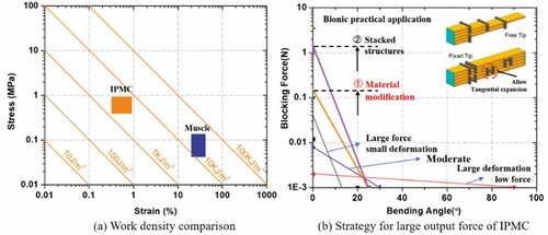
A strategy to meet the actuation requirements of the IPMC was proposed based on bending stacked actuator, which includes the two steps shown in ). ① Develop an improved IPMC material with high power density that can produce force of more than 100 mN based on the premise that the bending angle is greater than 20° and the response time does not exceed 1 s. ② Develop a highly efficient stacked bending technology that can transmit the force among the bending layers with low internal losses. A ten-layer stacked actuator based on the improved IPMC and the stacked technology can produce a 1-N-level force, as required. The second step was verified in Ref. [Citation11], in which the stacking principles in the directions of width, thickness, and length were all discussed. A sliding joint between two layers connected in the thickness direction was used to deliver the normal force and also allow tangential motion.
To realize the IPMC performance described in step ①, an acceleration technology with a high impulsive stimulus was developed previously in our laboratory [Citation12]. IPMC deformation can be accelerated by tens of times without causing electrolysis damage. This means that an IPMC with a response time on the 10s level under a step voltage can easily reach the required steady-state deformation in approximately 1 s under application of an impulse voltage. However, this acceleration cannot be extended infinitely because the material is restrained by the physical limitations of ion mobility and heat accumulation [Citation13]. Based on our experience, when the material thickness exceeds 1 mm, it is difficult to realize a response time of less than 1 s for the IPMC, even under application of an impulse voltage. To obtain the high power density IPMC described in step ①, the thickness of the improved IPMC should thus be less than 1 mm. Under the condition that the bending angle is not less than 20°, the main goal of this work is to enhance the actuation force as much as possible.
An IPMC is composed of an ionic polymer substrate and two electrode layers. When applying a low voltage, the mobile ions in the polymer migrate from the anode toward the cathode with some water molecules, and this leads to the bending deformation. The lithium ion represents the best choice for high-speed actuation. The main development directions for optimization of the IPMC performance thus involve modification of the substrate polymer and electrode materials. One way to modify the substrate polymer is to develop new ionic polymers. To date, Nafion polymer is still regarded as the benchmark material for IPMC substrates [Citation14], and it is also used as the base polymer here. The other approach is to dope the substrate with functional nanomaterials. The carbon nanotube (CNT) is the most representative material for such doping applications [Citation15]. With regard to the electrode materials, Kim and our group developed an optimized process for fabrication of Pt-Nafion and Pd-Nafion IPMCs successively based on the orthogonal optimization method [Citation16,Citation17]. In contrast to consideration of the electrode material itself, an electrode-polymer interface with a high specific surface area is more critical to the actuation performance. Sandblasting during the pretreatment stage is quite effective for production of a rough surface morphology prior to plating. To obtain a higher specific surface area, hot pressing with a rough template (e.g. electrochemically etched Al foil) and a microneedle roller roughening process were applied to the substrate membrane [Citation18,Citation19]. Recently, Park proposed an isopropyl alcohol-assisted plating process to cause the membrane to swell before plating. This method increased both the interfacial area and the actuation performance successfully [Citation20].
However, all these approaches are still unable to reach the requirement described in step ①. The main reason for this is that the techniques pursue either large deformation or a high blocking force separately, usually by optimizing a single factor. Here, we propose a new approach to enhance the actuation force by integrated optimization of multiple factors. After consideration of the availability of modified ionic polymers and high-performance doping fillers, we selected Nafion polymer as the substrate material; casting a thick Nafion membrane (thinner than 1 mm) and doping it with typical CNTs serve as the basic methods to improve the actuation force, and then these methods are combined with physical (hot pressing with a rough surface template) and chemical (isopropyl alcohol-assisted plating) processes to enlarge the electrode interface area and ultimately improve the actuation performance comprehensively. It should be noted that although doping with RuO2 can improve the actuation performance of an IPMC [Citation21], it also has a serious effect on its response speed, which is not considered within the experimental design presented here.
Therefore, integrated optimization of the IPMC fabrication process with multiple factors is investigated in this paper for application to the stacked actuators used in soft robots and devices. The difficulty of integrating the optimization processes lies in the possibility of interference among the various factors. After introduction of the basic fabrication processes and characterization methods in Section 2, IPMC performance optimization is first analyzed with respect to each single factor in Section 3, and then multiple-factor optimization is studied in Section 4. Conclusions are drawn in the final section.
2. Experimental procedure
2.1 IPMC preparation
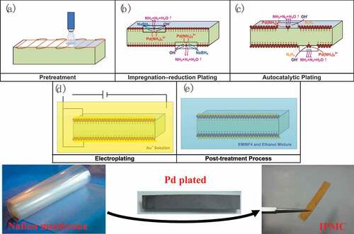
As shown in , a general IPMC fabrication process based on the chemical plating method includes five key steps [Citation11]. (a) Pretreatment: treatment of the commercial ion exchange membrane by sandblasting to form a rough surface, which can promote the chemical reaction at the membrane surface during the fabrication process. (b) Impregnation-reduction plating: this involves first exchanging Pd(NH3)42+ in the ion exchange membrane and then reducing it to form Pd micro particles on the membrane surface with a NaBH4 solution to form the metal electrode of the IPMC. (c) Autocatalytic plating: the membrane is placed into a Pd(NH3)42+ alkaline solution and a N2H4 solution is added step-by-step to produce an autocatalytic reaction, which can then form a thicker Pd electrode layer and reduce the surface resistance. (d) Electroplating: a layer of the gold electrode is covered by the electroplating method to form a protective layer and also further reduce the surface resistance. (e) Post-treatment processing: exchanging within the membrane, with Li+ acting as the driving ion of the IPMC. The chemicals NaBH4, N2H4, NH3H2O, Na2EDTA (disodium ethylenediaminetetraacetate), and polyvinylpyrrolidone (PVP) were obtained from Sinopharm Chemical Reagent Co., Ltd., and the LiOH was obtained from Shandong West Asia Chemical Industry Co., Ltd.
Figure 2. General fabrication process for the IPMC.
Based on this common and conventional IPMC fabrication process, this paper proposes a comprehensive multi-factor optimization fabrication process that includes a membrane casting process, a CNT doping process, isopropyl alcohol-assisted plating, and a mesoscopic structure hot pressing process. A brief introduction to each aspect is given in the following.
2.1.1. Nafion membrane casting process
The Nafion membrane thickness is tunable via the membrane casting process, which can also vary the mechanical properties of the IPMC and improve its output force [Citation11]. First, the dimethylacetamide (DMAc) and Nafion solution (DE520, 5 wt.%, obtained from Dupont) are mixed together and stirred for 4 h. Then, the solution is transferred into a glass mold and a vacuum for several minutes to remove any micro-bubbles. The solution is then heated for 96 h at 80°C and annealed at 120°C for 3 h in an oven. Finally, a Nafion membrane with a controllable thickness is obtained.
2.1.2. CNT doping process
CNTs are widely used in polymer doping process because of their superior mechanical properties (high strength, high modulus, etc.) and electrical properties (good electrical conductivity, etc.). When doping CNT into Nafion membrane, it can improve the modulus and electrical conductivity of IPMC and further enhance the output force performance. Carboxylated CNT (CCNT) shows great water-dispersion performance and good electrochemical properties. Moreover, it offers additional cations of COOH-, which facilitates the generation of hydrated cations in the driving process. When applying a voltage, there are more hydrated cations move from anode to cathode in the IPMC actuator, which will form a greater deformation. Therefore, CCNT doping method used to fabricate CCNT-doped Nafion membranes can both improve the output force and the deformation performance [Citation22].
The CCNT used in this work was purchased from the Chinese Academy of Sciences Chengdu Organic Chemical Co. Ltd. The most important step is the preparation of the CCNT dispersion solution. First, 0.2 g of dispersant (TNWDIS), 0.2 g of ionic liquids, 1.0 g of CCNTs, and 48.6 g of deionized water are mixed together intensively using a magnetic stirrer for at least 4 h; then, the mixed solution is treated with ultrasound for 5 min using a cell crusher before it is cooled down in an ice bath. The total ultrasonic treatment time should be at least 2 h. Finally, we obtain the CCNT dispersion solution. Using the casting method described above, the CCNT-doped membrane can be fabricated by casting a mixed solution composed of the CCNT dispersion solution, Nafion, and DMAc.
2.1.3. Isopropyl alcohol-assisted plating
Isopropyl alcohol is able to expand the Nafion polymer networks, which can promote the growth of metal particles during the impregnation reduction step to form an electrode with deeper penetration and a larger effective interface area. The penetrated and interlaced interface of membrane and electrode shows better capacitance characteristics and can accommodate more cations in the driving process, which will improve the electrochemical properties and lead to good actuation performance in the IPMC [Citation20]. To obtain an optimized isopropyl alcohol-assisted plating process, the following two groups of experiments were conducted.
Group 1. The optimum ratio of isopropyl alcohol to water during plating was investigated. The isopropyl alcohol was obtained from Sinopharm Chemical Reagent Co., Ltd. Four mixed solutions were prepared with their volume ratios of isopropyl alcohol to water increasing gradually from 0:6, 2:6, and 3:6 to 6:6. During the impregnation reduction plating process, the membrane that was exchanged with Pd(NH3)42+ was placed into a mixed solution with various isopropyl alcohol-to-water ratios to conduct the reduction plating process.
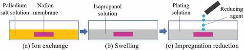
Group 2. The swelling time and the manner which the swelling occurred in the optimum isopropanol solution were investigated. As shown in , the membrane that had been exchanged with Pd(NH3)42+ was placed into an isopropanol solution with the optimum isopropyl alcohol-to-water ratio that was obtained in Group 1 before reduction plating and after the ion exchange process. By changing the swelling time in given (b), the extent of the swelling reached a steady state in approximately 2 h. Two IPMC samples were then fabricated for comparison based on the condition of swelling for 2 h in the first impregnation reduction solution and the condition of swelling for 2 h in all three impregnation reduction solutions separately.
Figure 3. Illustration of isopropyl alcohol-assisted reduction plating steps.
2.1.1. Mesoscopic structure mold
According to the actuation structure of IPMC, the two electrodes outside and the substrate membrane constitute the plate capacitor structure. When the interface area between the electrode and the matrix film increases, the specific capacitance of IPMC and its charge storage capacity will also increase. As a result, the cathode interface will be able to hold more hydrated cations moving from the positive electrode to the negative electrode, which shows greater expansion and deformation of IPMC. The mesoscopic structure electrode combined with the sand-blasting method can fabricate composite structured interface, which greatly increases the interface area, and finally enhances the electroactive performance.
To study the effect of the membrane surface area on the performance improvement of the IPMC quantitatively, IPMCs were fabricated with mesoscopic hole arrays on their surfaces via hot pressing with micro-column structured molds. The key step in this case is the fabrication of the micro-column structure mold used for hot pressing. First, a microscale cylindrical hole array was produced on the wafer surface by dry etching, as shown in ). Then, a polydimethylsiloxane (PDMS; Sylgard 184, Dow Corning) solution was cast on the wafer surface. After curing, the PDMS film was peeled from the wafer. The film is shown in ) as a mold with micro-columns. As illustrated in ), the surface area of the Nafion membrane can be improved further by forming random microstructures on the 1 μm scale via sandblasting after hot pressing. This combination of hot pressing and sandblasting processes will cause the electrode-polymer interface area of the IPMC to be greatly increased after plating.
Figure 4. Silicon and PDMS molds for Nafion with a mesoscopic structure formed by hot pressing.
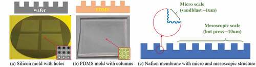
Given that the microscale structure produced by sand blasting is of the order of 1 μm in size (ranging up to 4 μm in Ref. [Citation23]), the mesoscopic scale was set to be in the 10 μm–100 μm range (where the membrane thickness is on the 100 μm scale), which is the characteristic scale for either the holes on the membrane surface or the columns of the PDMS molds. Through multiple attempts during the early stages, it was found that the hole size was also limited by the hot pressing process. When the depth-to-aperture ratio was greater than 2, the hole structure with the large aspect ratio was easy to tilt. Additionally, when the hole diameter was too small (i.e. <20 μm), it was then difficult to prepare holes with large depths. With regard to the hole spacing, consideration of the structural strength means that the spacing should not be smaller than the hole diameter. Here, we set the hole spacing to be the same as the hole diameter. Finally, for the subsequent hot pressing experiments, various PDMS molds were prepared with different column diameters of 40, 60, and 80 μm, and the aspect ratio was limited to be no greater than 2.
2.1.5 Hot pressing process
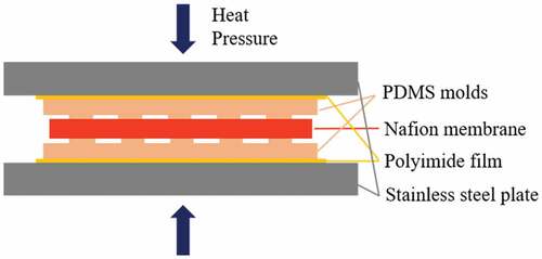
The hot pressing process can reshape the Nafion membrane structure by applying pressure to it when the temperature exceeds its transition temperature of 140°C. Before hot pressing, the PDMS molds, the Nafion membrane, and the protective polyimide films were assembled together as shown in . First, the temperature of the hot press machine was set at 180°C and this temperature was maintained for 4 min to soften the Nafion membrane sufficiently. Then, the pressure of the hot press machine was set at 0.2 MPa, and the pressure and temperature were maintained for 30 min to ensure that the mesoscopic structure on the PDMS molds was transferred onto the Nafion membrane surface completely. Finally, the pressure was released, the heating switch was turned off, and the Nafion membrane cooled down naturally to room temperature on the workbench of the hot press machine.
Figure 5. Layout of the Nafion membrane and the PDMS dies under the hot press.
2.2 Characterization of electromechanical properties of IPMC
For the IPMC based on commercial Nafion-117 membrane, the back relaxation can be completely removed by removing about 4% water content in it. In addition, for the IPMC based on casting Nafion membrane, the water content property is a little different from that of Nafion-117 based IPMC. Especially for a thick IPMC (larger than 0.2 mm), the total water content is a little smaller than that of Nafion-117 based IPMC [Citation24]. Therefore, when picking up a thick IPMC from water and applying a voltage, it usually shows no back relaxation. In this paper, all the experiments were performed at the same environmental condition, and all IPMCs showed no back relaxation.
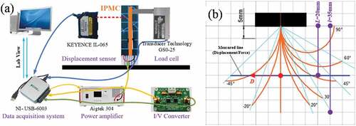
) shows a schematic of the test platform, which was composed of a personal computer (PC) acting as the controller, a data acquisition card (USB-6003, NI), a power amplifier (304, Aigtek), a laser displacement sensor (IL-065, Keyence), a load cell (GS0-25, Transducer Techniques), and a clamp that can hold an IPMC strip with a free length of l = 35 mm (full length: 40 mm) and a width of w = 5 mm. During testing, a programmed signal controlled by LabVIEW software was generated in the data acquisition card, amplified by the power amplifier, and finally applied to the test sample. During bending of the IPMC strip, the laser displacement sensor measured the bending deformation D or the load cell measured the blocking force F at a point L = 20 mm away from the clamp, as shown in ). For a cantilever with a free length of 35 mm, the bending angle will exceed 20° if the displacement measured at L = 20 mm is greater than
5 mm. When the bending angle is greater than 60° (the bending that usually occurs under application of a DC voltage), the measured displacement cannot reflect the IPMC deflection well. As a supplementary measure, a camera was used to record a video immediately above the bending IPMC, and the frame that captured the largest deformation was used to determine the steady-state bending angle. All signals for the displacement, the blocking force, and the applied voltage and current acquired via a current-to-voltage (I/V) converter were recorded using the data acquisition card. All experiments were performed in unified conditions composed of room temperature in air at ambient humidity (20°C, 55% relative humidity (RH)).
Figure 6. Illustration of (a) the IPMC performance test platform and (b) the test point when bending occurs.
2.3 Comprehensive evaluation of actuation performance
Usually, the bending frequency of bionic soft robots, e.g. for fish tails and inchworms, is at the 0.1–1 Hz level. Under application of an appropriately high impulse voltage, the response speed of the IPMC can increase by one to two orders of magnitude. The deformation and output force performance at 0.1 Hz can be obtained at 1 Hz as a conservative estimate under application of the high impulse voltage. In addition to measurement of the bending deformation and the blocking force under a DC voltage as a measure of the maximum actuation ability, the bending deformation is also measured under application of a square voltage (0.1 Hz) as a performance measure that is valuable for different bionic applications. In this paper, we utilize the work density to evaluate the comprehensive electro-active performance of each IPMC. To accurately evaluate the work density, the calculating model should consider the complex eigenstress associated with osmotic pressure, Maxwell stress and the changing surface electrical resistance along the longitude in the sandwich structure of IPMC, and analysis the multiaxial deformations in the ionomer, especially, through-the-thickness strain located in the vicinity of the ionomer-electrode interfaces [Citation25–27]. Because all the samples were test under the same condition, this paper tend to approximately compare the work density of each sample in an engineering approximate evaluation method based on the traditional hypothesis [Citation28,Citation29] of pure bending deformation and the Euler–Bernoulli Beam theory. Compared to the accurate model, this calculation process is relatively simply but rough, and the specific process is given in the Supplementary Materials. The volume work density
can be approximately calculated as Equation (1):
where, is the volume work density;
and
refers to the maximum stress and strain that occur at the surface of the IPMC; E refers to the effective bending elastic modulus, which can be measured as shown in supplementary materials; t refers to the thickness of the IPMC;
and
refers to the measure distance and deformation displacement of the IPMC, respectively. Alternatively, Wd can be calculated based on the bending angle:
where, is length of the IPMC, and
refers to the deformation angle of the IPMC. Because the work density measured at 0.1 Hz can easily be obtained at 1 Hz under application of an impulse voltage, the value of
is regarded as being equal to the average power density throughout this paper.
It should be noticed that the calculation of in an engineering evaluation method, which approximately shows the comprehensive performance and cannot reflect the precise behavior of each IPMC sample. In addition, detailed measurement methods for the capacitance, elastic modulus, and surface resistivity of the electrode and the surface, and for the cross-sectional morphology are introduced in the Supplementary Materials.
3. IPMC performance optimization with single factor
3.1 CCNT-doped IPMC
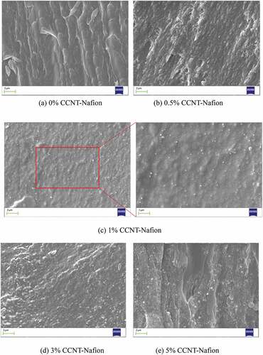
The CNT content for doping of Nafion polymer is usually no higher than 5 wt.%; otherwise, it becomes easy to cause agglomeration of the nanoparticles. To investigate the effect of CNT doping on the actuation performance of the IPMC, five Nafion membranes with 0 wt.%, 0.5 wt.%, 1 wt.%, 3 wt.%, and 5 wt.% CCNT contents were prepared by combining the Nafion casting and CNT doping processes. The thickness of each of these Nafion membranes was approximately 0.5 mm. Using the general IPMC process, five IPMCs were fabricated and cut into strips with dimensions of 40 mm × 5 mm. The cross-sections of Nafion membranes without and with CCNT doping are shown in . The SEM images clearly show that the 0.5 wt.% and 1 wt.% CCNT particles were well dispersed within the polymer. As the CCNT content increasing, the bright white points grew bigger as in (,e,) which shows the CCNT particles gradually agglomerated. The size of the bright white points in the images represents the degree of agglomeration.
Figure 7. Cross-sectional scanning electron microscope (SEM) images of Nafion membranes with and without the doped CCNT particles. (a) 0% CCNT-Nafion. (b) 0.5% CCNT-Nafion. (c) 1% CCNT-Nafion. (d) 3% CCNT-Nafion. (e) 5% CCNT-Nafion.
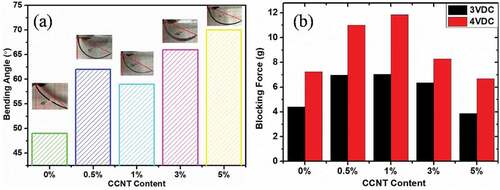
Under application of a DC voltage, the deformation and the blocking force can reflect the maximum driving capacity of the IPMC. Additionally, because the internal resistance increases with increasing thickness, a thicker IPMC can work safely under application of DC voltages of 3 V or higher. Here, we mainly measured the steady-state displacement or the bending angle and blocking force under application of 3 VDC, and measured the blocking force under application of 4 VDC to evaluate the maximum available force. The bending angle was far greater than 20° under the 3 VDC signal, and thus the corresponding angle under application of 4 VDC was not measured. The results are shown in . As the CCNT content increased, the bending angle under application of 3 VDC increased from 49° to 70°, except in the case where a slight decline showed at 1 wt.%, and the blocking force initially increased from 4.40 gf/7.23 gf to 7.10 gf/11.84 gf before decreasing to 3.90 gf/6.69 gf under application of 3 VDC/4 VDC. The IPMC doped with 1 wt.% of CCNTs showed a large actuation force but relatively small deformation, whereas the 5 wt.% CCNT-doped IPMC showed the opposite trends. When the volume work density values of these samples are compared, that of the former sample (13.31 kJ/m3) is greater than that of the latter sample (8.02 kJ/m3).
Figure 8. (a) Bending angles under 3 VDC application, and (b) blocking forces under 3 and 4 VDC application for IPMCs with various CCNT doping contents at a point located 20 mm away from the clamp.
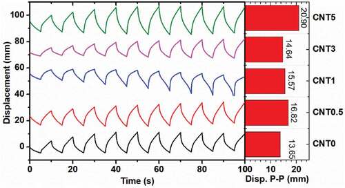
To evaluate the response speed characteristics, IPMC deformations under application of an AC voltage of 3 V at 0.1 Hz were measured, giving results that reflect the deformation performance at 1 Hz under a high impulse stimulus. The results for the five IPMCs with various CCNT contents are shown in (where sample CNTx means the IPMC doped with x wt.% of CCNTs). The bending amplitudes initially increased for a few cycles and then reached a stable state. As the CCNT content increased, the stable bending amplitude showed a growing trend overall, with a slight decline for the IPMC with the 3 wt.% CCNT content. The highest peak-to-peak displacement among them was 20.90 mm for the IPMC with the 5 wt.% CCNT content. All samples showed displacements of more than 5 mm, which means that their bending angles were all greater than
20°.
Figure 9. Displacements of IPMCs with various CCNT doping contents at a point located 20 mm away from the clamp under application of a square waveform voltage (3 V, 0.1 Hz).
To probe the influence of the CCNT doping content, the surface resistivity, elastic modulus, and effective capacitance values of the five samples were measured, and the results are listed in . As noted in Ref. [Citation30], the voltage profile along the sample length will show an apparent decline and cause a weak deformation if the surface resistance of the IPMC is too large (of the order of 100 Ω/□). Here, the surface resistivity was in the 0.3 ~ 0.9 Ω/□ range, which guaranteed that no voltage decline would occur along the length of all the samples. The elastic modulus initially increased and then decreased with increasing CCNT content, reaching a maximum of 369 MPa when the content was 1 wt.%. As the CCNT content increased further, the agglomeration of the CCNT particles became more serious, as observed in cross-sectional SEM images of the Nafion membrane. The continuity of the substrate membrane was destroyed, and this resulted in a loose internal structure and a reduction of the elastic modulus. Additionally, the effective capacitance increased from 19.05 to 48.18 mF/cm2 and then decreased slightly to 42.88 mF/cm2 for the 5 wt.% CCNT-doped IPMC. In , the larger deformations of the IPMCs doped with high CCNT contents (3–5 wt.%) were caused by huge increases in the capacitance, and the high blocking force of the 1 wt.% CCNT-doped IPMC can be ascribed to its high elastic modulus. Following consideration of the maximization of the volume work density, the optimum CCNT doping content for the IPMC was confirmed to be 1 wt.%.
Table 1. Electromechanical properties of IPMCs with various CCNT doping contents.
3.2 Isopropyl alcohol-assisted plated IPMC
Two groups of experiments were designed to investigate the influence of the isopropyl alcohol concentration and the swelling time on the actuation performance of the IPMCs, with results as shown in . In this batch of experiments, the substrate membrane was re-cast with a thickness of 0.8 mm because of certain deviations that occurred in the casting process. However, the absolute film thickness rarely varies the influence of the plating method on the actuation performance. After impregnation reduction, all samples were subjected to chemical plating three times. The prepared IPMC samples were also cut into 40 mm × 5 mm sections.
Table 2. Experimental design of isopropyl alcohol-assisted reduction plating.
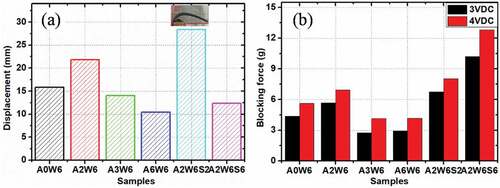
The deformations under application of 3 VDC and the blocking forces under application of 3 and 4 VDC for all samples are shown in . Group 1: As the isopropyl alcohol concentration increased, the deformation initially increased from 15.83 mm to 21.84 mm, and then decreased to 10.46 mm. The blocking force also showed a similar tendency, first increasing from 4.38 gf/5.64 gf to 5.67 gf/6.93 gf, and then decreasing to 2.94 gf/4.17 gf under application of 3 VDC/4 VDC. Sample A2W6 showed the greatest bending deformation and the highest blocking force. The optimum ratio of isopropyl alcohol to water was set at 2:6 for the study shown in Group 2. Sample A2W6S2 showed an ultra-large deformation under application of 3 VDC that was even beyond the measurement range of the laser meter. The bending angle of 87° was captured using a camera. Additionally, sample A2W6S6 showed the highest blocking forces of 10.19 gf/12.79 gf with small amounts of bending. When their volume work density values were compared, A2W6S2 still showed a higher density (12.85 kJ/m3) than that (10.01 kJ/m3) of A2W6S6.
Figure 10. (a) Displacement under application of 3 VDC and (b) blocking force under application of 3 and 4 VDC of isopropyl alcohol-assisted plating IPMCs at a point located 20 mm away from the clamp.
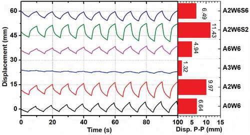
Isopropyl alcohol-assisted plated IPMC deformations measured under an AC voltage of 3 V at 0.1 Hz are shown in . Most IPMCs showed a peak-to-peak value of less than 10 mm, which indicates bending angles that were smaller than 20°. This result was mainly due to the increase in the substrate thickness. In Group 1, sample A2W6 showed the largest peak-to-peak amplitude (9.97 mm). The corresponding amplitude increased further to 11.43 mm in Group 2. The variation of the dynamic deformation with the isopropyl alcohol concentration and the swelling time is similar to that of the steady-state deformation shown in .
Figure 11. Displacement of isopropyl alcohol-assisted plating IPMCs at a point located 20 mm away from the clamp under application of a square waveform voltage (3 V, 0.1 Hz).
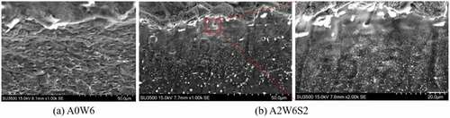
Isopropyl alcohol-assisted plating mainly enhanced the reduced Pd particle density during the impregnation reduction step by expanding the polymer network, particularly at the polymer boundary. As shown in , in contrast to reference sample A0W6, the metal particle (indicated by white bright points) density was apparently much richer at the electrode-polymer interface of A2W6S2.
Figure 12. SEM images acquired at the electrode-polymer interface of the IPMCs without and with isopropyl alcohol-assisted plating.
The electromechanical properties of all the isopropyl alcohol-assisted plated IPMCs were measured and are listed in . The surface resistivity of the IPMCs in Group 1 was in the range from 1–3 Ω/□, which was slightly higher than that (0.07–1 Ω/□) measured in Group 2. The higher resistance of Group 1 weakened the overall actuation performance. However, the influence of the resistance was quite limited, based on the results in Ref [Citation28]. The elastic moduli were slightly lower than in the reference sample without the isopropyl alcohol-assisted plating. By evaluating the water content of each sample, it was found that isopropanol addition during plating can increase the water uptake capacity and thus weaken the mechanical properties of the sample. Sample A2W6 showed the best actuation performance in Group 1, which can be ascribed to it having the highest capacitance and a moderate elastic modulus. Adding isopropanol to the plating solution in phase c in can weaken the mechanical properties of the IPMC. However, if the addition of the isopropyl alcohol was conducted before the reduction plating process, it resulted in both a higher elastic modulus and a higher capacitance. This is the reason why A2W6S2 and A2W6S6 exhibited large deformations and high blocking forces.
Table 3. Electromechanical properties of isopropyl alcohol-assisted plating IPMCs.
3.3 Hot pressed IPMCs
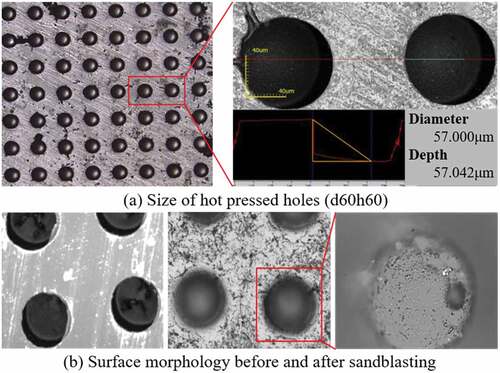
Two critical parameters of the mesoscopic surface structure, i.e. the diameter d and the depth h, were investigated in two groups of experiments. Based on the 0.5 mm casting of the Nafion membrane, the first group varied the diameter (40 μm, 60 μm, 80 μm) while maintaining the same depth (40 μm), including one reference sample without a mesoscopic structure, and the second group varied the depth (40 μm, 60 μm, 80 μm) while maintaining the same diameter (60 μm). The sample code dxhy means that its diameter is x μm and its depth is y μm. The surface morphologies of the hot pressed Nafion membranes are shown in . For sample d60h60, the practical diameter and depth of one hole when measured by confocal microscopy were 57.000 μm and 57.042 μm, respectively, as shown in ); these values were quite close to the designed 60 μm value. The surface area after hot pressing can be calculated to be
Figure 13. Surface morphology of hot-pressed Nafion membrane.
where ,
and
refers to the surface area, diameter of the mesoscopic holes and depth of the mesoscopic holes;
and
refers to the length and width of the IPMC. The hot-pressed mesoscopic structure was combined with the sandblasted microstructure to enhance the interfacial area. After sandblasting, rough surfaces can be seen at both the top surface of the membrane and the bottom surface of the hole in ). All these images verified that the hot pressing method developed in this paper was effective in enlarging the surface area of the membrane.
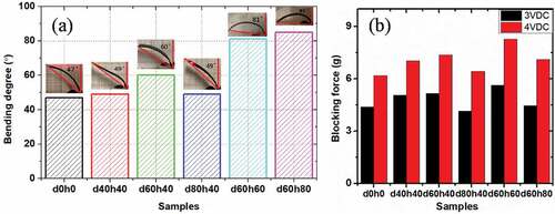
The deformations under application of 3 VDC and the blocking forces under application of 3 and 4 VDC for all the hot-pressed IPMCs are shown in . Generally, almost all the deformations and blocking forces of the IPMCs after hot pressing were higher than those of the reference sample (d0h0). Group 1: As the hole diameter increased from 40 to 80 μm, the bending angle increased from 47° to 60° and then decreased to 49°, as shown in ). Additionally, the blocking force also increased initially from 4.4 gf/6.18 gf to 5.17 gf/7.37 gf, and then decreased to 4.15 gf/6.42 gf under application of 3 VDC/4 VDC. Sample d60h40 showed both the largest bending angle and the highest blocking force. Then, the diameter was set at 60 μm and the depth was varied from 40 μm to 80 μm in Group 2. As the depth increased, the bending angle also increased from 60° (d60h40) to 85° (d60h80), and the blocking force initially increased from 5.17 gf/7.37 gf to 5.64 gf/8.28 gf before decreasing to 4.46 gf/7.12 gf. When the volume work densities were compared, d60h60 showed the highest density (12.78 kJ/m3) and was then followed by d60h80 (11.00 kJ/m3).
Figure 14. (a) Bending angles and (b) blocking forces under application of 3 VDC for various hot pressed IPMCs at a point located 20 mm away from the clamp.
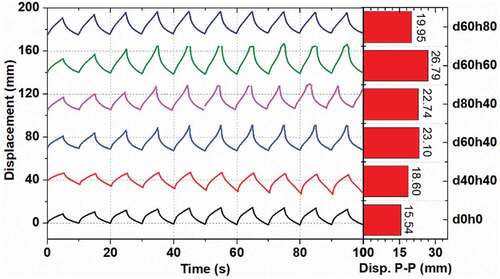
Hot-pressed IPMC deformations under application of an AC voltage of 3 V at 0.1 Hz are shown in . The bending deformations were much greater than those of the previous two results overall. In Group 1, the peak-to-peak deformation amplitude initially increased and then decreased with increasing diameter. Additionally, in Group 2, sample d60h60 showed the greatest bending displacement. The possible reason is that sample d60h60 showed a faster response speed. Because all samples show good deformation performances that are much greater than °, the blocking force becomes a more important concern. Sample d60h60 was then assessed to be the best among all the hot-pressed IPMCs.
Figure 15. Displacement of various hot pressed IPMCs at a point located 20 mm away from the clamp under application of a square waveform voltage (3 V, 0.1 Hz).
The electromechanical properties of all the hot-pressed plated IPMCs were measured, and the results are listed in . All the surface resistivity values of the IPMCs were in the range from 2–3 Ω/□. Although the resistance level rarely shows any influence on the deformation, it is suggested that the resistivity could be reduced further to be less than 1 Ω/□ by electroplating the samples further with a gold layer [Citation11]. Additionally, for Group 1, all elastic moduli were concentrated in the 153–161 MPa range. The good actuation performance of sample d60h40 can be ascribed to its high capacitance (45.68 mF/cm2). In Group 2, the capacitance increased further with increasing depth to 52.66 mF/cm2. Although sample d60h80 had a larger mesoscopic structure area, the bottoms of the holes were difficult to reach by sandblasting. The electrode-polymer interfacial area did not increase linearly with increasing depth. Therefore, a moderate depth such as that of sample d60h60 produced the best actuation performance.
Table 4. Electromechanical properties of the hot-pressed IPMCs.
Overall, the three methods were all able to improve the capacitance effectively. The hot pressing method showed the best results. Sample d60h60 had the highest capacitance (52.66 mF/cm2), which resulted in a relatively large bending angle and a high blocking force. The CNT doping method produces a high blocking force by improving the elastic modulus. Sample CNT1 showed the highest elastic modulus of 369 MPa, and this led to the highest blocking forces of 7.10 gf/11.84 gf under application of 3 VDC/4 VDC among the IPMCs with the 0.5-mm-thick substrate membrane. Most isopropyl alcohol-assisted plated IPMCs showed relative low elastic moduli because of their increased water uptake and low blocking forces. Swelling of the membrane in advance before the reduction reaction can overcome this shortcoming well. Sample A2W6S2 showed the largest bending angle of 87°, while A2W6S6 exhibited the highest blocking forces of 10.19 gf/12.79 gf under 3 VDC/4 VDC applications, which occurred partly because it had a thicker substrate membrane (0.8 mm).
4. Integration of fabrication process with multiple optimized factors
To improve the blocking force and the work density of the IPMC, we tried to integrate the previous three methods with the best process parameters into a single fabrication process step-by-step. The CCNT doping and isopropyl alcohol-assisted plating methods were not in conflict with each other. They were considered for combination into one fabrication process at first. Then, the integration of the fabrication process with multiple optimized factors was designed as shown in . R7 was the reference sample, which we fabricated using the normal five-step process. A7 was the sample fabricated using the same process as A2W6S2. AC7 was the sample that was fabricated using the same process as A2W6S2 and based on a 1 wt.% CCNT-doped Nafion membrane. In addition, ACH7 was the sample that was further combined with the hot-pressing process of sample d60h60 based on the AC7 fabrication process.
Table 5. Integration design of fabrication process with multiple optimized factors.
The sample thickness is also a critical parameter for enhancement of the blocking force. Based on consideration of the response speed requirement, the thickness was roughly set to be thinner than 1 mm at the beginning. By comparing the deformations under application of the 3 VAC voltage for the three reference samples shown in , , and , it was found that the peak-to-peak amplitudes are greater than mm (
°) when the thickness is 0.5 mm and lower than
mm when the thickness is 0.8 mm. After a few trials with different thicknesses ranging between 0.5 and 0.8 mm, it was found that the largest thickness that fulfilled the dynamic deformation requirement of
mm was approximately 0.7 mm, based on the normal fabrication process. The substrate membrane thickness here was set at 0.7 mm to obtain the results shown in .
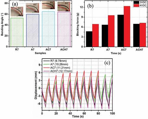
The deformations under application of 3 VDC and the blocking forces under 3 and 4 VDC of the IPMCs are shown in ), respectively. Sample AC7 showed the largest bending deformation (65°) and the highest blocking forces of 9.71 gf/12.36 gf under voltages of 3 VDC/4 VDC. Sample ACH7 was expected to be the best of the IPMCs. However, it showed a similar bending angle (64°) and low blocking forces of 6.96 gf/7.26 gf under the voltages of 3 VDC/4 VDC. Additionally, in ), reference sample R7 showed a 9.78 mm peak-to-peak bending displacement, which would just fulfill the requirement for deformation of ° at 0.1 Hz. The deformation of sample ACH7 was slightly larger than that of sample AC7. Therefore, sample AC7 produced the best actuation performance.
Figure 16. (a) Bending angles and (b) blocking forces under application of 3 VDC, and (c) displacement under application of a square waveform voltage (3 V, 0.1 Hz) for various hot-pressed IPMCs at a point located 20 mm away from the clamp.
We listed various typical IPMCs and their actuation performances in for comparison. The IPMCs with the thicker membrane (0.7 mm) showed smaller bending angles in contrast to the IPMCs with the 0.5 mm membrane thickness. Furthermore, these IPMCs, including sample A7, still cannot match the large bending angle of sample A2W6S2 with the 0.8 mm membrane thickness. These results prove that isopropyl alcohol-assisted plating has great potential for providing large bending deformation, and also imply that the deformation is not so stable here. If we exclude sample A2W6S6, which cannot satisfy the requirements for both deformation and response speed, sample AC7 shows the highest blocking force (9.71 gf). With regard to the volume work density, the values of samples d60h60 and AC7 are the highest, that are close to each other. The hot-pressing method shows considerable potential to produce high work densities. If this method can be combined well with the doping and isopropyl alcohol-assisted methods, it will greatly enhance the actuation performance of the IPMC. However, the trial involving sample ACH7 failed.
Table 6. Performance comparison of various IPMCs (35 mm × 5 mm, measured at L = 20 mm).
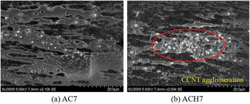
To reveal the cause of the failure in ACH7, cross-sectional SEM images of samples AC7 and ACH7 were captured, and are shown in . Because of the great conductivity, the doped CCNT particles show bright white point in the SEM images. The images show that the CCNT particles are well dispersed within the polymer membrane in AC7, whereas the CCNT particles are seriously agglomerated in ACH7. During the hot-pressing process, the substrate membrane is subjected to high pressure and a high temperature that is beyond its transition temperature of 140°C. The membrane is thus in a softened state, and the well-dispersed CCNT particles then tend to agglomerate under the pressure. The agglomeration of the CCNT particles changes the dispersion rate of the membrane and leads to stress concentration and the mechanical properties decline of ACH7, which is similar to that in the case of CCNT5 doping. Apparently, the declined elasticity modulus of ACH7 has negative influences on the output force performance which was lower than AC7. At the meantime, the appearance of agglomeration weakens the effect of doped CCNT, reduces the ionic conductivity of IPMC, which slows down the ion migration process, leads to a lower deformation performance. Therefore, to combine the doping method and the mesoscopic structure together, it will be necessary to avoid applying both high temperature and high pressure.
Figure 17. SEM images of CCNT-doped Nafion membrane without and with hot pressing.
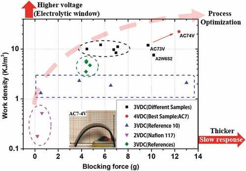
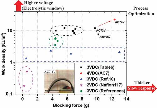
A summary of the IPMC actuation performances is shown in that focuses on the blocking force and the work density, i.e. the power density available at 1 Hz. Conventional Nafion-117 based IPMCs (~180 μm) generate a blocking force of less than 1 gf and a work density of less than 1 kJ/m3 under application of 2 VDC (magenta cycle) [Citation17,Citation23,Citation28]. To obtain a larger force, use of a thicker substrate membrane produced by hot pressing or casting and application of a higher voltage are the easiest methods to realize. Reference [Citation10] represents a typical report, in which the force increased from 0.5 to 13 gf (blue rectangle) gradually under application of 3 VDC as the thickness increased from 190 μm to 1340 μm. However, increasing the thickness alone tends to slow down the response speed seriously, and it is also not helpful for the work density value, which is restricted to within the range from 1–3 kJ/m3. In this paper, the work density of the reference samples in each group (CNT0, A0W6, d0h0, R7) is approximately 3–5 kJ/m3. To increase the work density further, physical or chemical processes that can enhance the mechanical and electrical properties of the substrate membrane or the electrode interface are required. In the black cycle, the work density of the IPMCs that were optimized with respect to one single factor can reach a level of 10 kJ/m3 under a voltage of 3 VDC. The best sample was AC7, which was optimized with multiple factors and shows a much higher blocking force of 9.71 gf. This sample can generate a bending angle as large as 94° under a voltage of 4 VDC and a peak-to-peak displacement of 25 mm under 4 VAC at a point located 20 mm away from the clamp. The maximum work density can reach 31.89 kJ/m3. Naturally, the applied voltage cannot be higher than the electrolytic window of the Nafion-water system, or it will cause unstable deformation or damage. The process optimization approach with multiple factors represents a reliable way to achieve higher forces and work densities in the near future.
Figure 18. Summary of IPMC actuation performances and tendencies.
5. Conclusions
To meet the requirements of flexible bending actuators for use in practical soft robots and devices, a strategy was proposed based on fabrication of a stacked bending actuator with high-speed and high-output-force IPMC strips. In this paper, a method for fabrication process integration with multiple optimized factors was used to produce such an IPMC material. CCNT doping, isopropyl alcohol-assisted plating, and hot pressing using a mesoscopic structural mold were selected as the typical optimization methods for use in the process integration here. The CNT doping method produces a high blocking force by improving the elastic modulus. The sample doped with 1 wt.% CCNT content shows the highest elastic modulus and leads to the highest blocking force under the condition that a 0.5-mm-thick substrate membrane is used. Before the reduction reaction, swelling of the membrane in advance is necessary; 2 h of swelling in a 25% isopropyl alcohol solution is sufficient to obtain ultra-large bending. Hot pressing with a mesoscopic structural mold represents the most effective way to realize a large capacitance. The IPMC with 60-μm-diameter and 60-μm-deep holes has both the largest capacitance and the highest work density.
By combining the best process parameters above in an integrated process, we obtained a sample (AC7) that produced an excellent actuation performance (9.71 gf/12.36 gf, 14.93/31.89 kJ/m3) under the condition that it could bend far enough and fast enough (as evaluated by the bending angle at 0.1 Hz). To our surprise, sample ACH7 was not the best performer. Agglomeration of the CCNT dopant particles under hot pressing conditions led to a decline in this sample’s mechanical properties and its poor performance. If the mesoscopic structure can be formed at room temperature using processes such as microneedle roller roughening, however, it is predicted that the actuation performance can be enhanced further. The performance of sample AC7 can meet the requirements of stacked IPMC actuators for practical bionic soft robots. To obtain a more powerful IPMC actuator, more optimization work is still required in practical engineering terms.
Supplemental Material
Download MS Word (28.8 KB)Supplemental Material
Download MS Word (612.6 KB)Acknowledgments
The authors acknowledge the financial support of Qian Xuesen Space Technology Laboratory Innovation workstation open fund, and the National Natural Science Foundation of China (NNSFC) (Grant No. 11802223, No. 61890961). This work was supported in part by grants from the Basic Research Project of China (No. JCKY2020110C074).
Disclosure statement
No potential conflict of interest was reported by the author(s).
Supplementary material
Supplemental data for this article can be accessed online at https://doi.org/10.1080/19475411.2022.2133187
Additional information
Funding
Related Research Data
References
- Mirvakili SM, Hunter IM. Artificial muscles: mechanisms, applications, and challenges. Adv Mater. 2018;30(6):1704407.1–1704407.28.
- Tiwari R, Garcia E. The state of understanding of ionic polymer metal composite architecture: a review. Smart Mater Struct. 2011;20(8):083001.
- Madden J, Vandesteeg NA, Anquetil PA, et al. Artificial muscle technology: physical principles and naval prospects. IEEE JOE. 2004;29(3):706–728.
- Zheng C, Um T, Bart-Smith H. Ionic polymer-metal composite artificial muscles in bio-inspired engineering research: underwater propulsion. Smart Actuation and Sensing Systems - Recent Advances and Future Challenges, Berselli G, Vertechy R, Vassura G. IntechOpen, London. 2012; 730.
- Cheng TH, Xuan DJ, Li ZZ, et al. Development of IPMC actuator for flapping motion of dragonfly. Adv Mat Res 2011; 1301–1304
- Tomita N, Takagi K, Asaka K. Development of a quadruped soft robot with fully IPMC body. Sice Conference IEEE. 2011;1687–1690.
- Fleming M, Fleming, Hubbard M, et al. Monolithic ipmc fins for propulsion and maneuvering in bioinspired underwater robotics. IEEE-JOE. 2014;39(3):540–551.
- Guo S, Shi L. A multifunctional underwater biomimetic microrobot . Robot Fish. Springer Tracts in Mechanical Engineering Du R, Li Z, Youcef-Toumi K, Valdivia y Alavado P. Springer Berlin Heidelberg; 2015: 29.
- Madden J, Schmid B, Hechinger M, et al. Application of polypyrrole actuators: feasibility of variable camber foils. IEEE JOE. 2004;29(3):738–749.
- Park JH, Lee SW, Song DS, et al. Highly enhanced force generation of ionic polymer-metal composite actuators via thickness manipulation. Acs Appl Mater Interfaces. 2015;7(30):16659–16667.
- Bian C, Zhu Z, Bai W, et al. Highly efficient structure design of bending stacking actuators based on IPMC with large output force. Smart Mater Struct. 2021;30:075033.
- Zhu Z, Bian C, Ru J, et al. Rapid deformation of IPMC under a high electrical pulse stimulus inspired by action potential. Smart Mater Struct. 2019;28:01LT01.
- Bian C, Zhu Z, Bai W, et al. Fast actuation properties of several typical IL-based ionic electro-active polymers under high impulse voltage. Smart Mater Struct. 2020;29(3):035014.
- Duncan AJ, Leo DJ, Long TE. Beyond nafion: charged macromolecules tailored for performance as ionic polymer transducers. Macromolecules. 2018;41(21):7765–7775.
- Ru J, Wang Y, Chang L, et al. Preparation and characterization of water-soluble carbon nanotube reinforced Nafion membranes and so-based ionic polymer metal composite actuators. Smart Mater Struct. 2016;25:095006.
- Kim KJ, Shahinpoor M. Ionic polymer–metal composites: II. manufacturing techniques. Smart Mater Struct. 2003;12(1):65.
- Chang L, Chen H, Zhu Z, et al. Manufacturing process and electrode properties of palladium-electroded ionic polymer–metal composite. Smart Mater Struct. 2012;21(6):065018.
- Chang L, Yang Q, Niu Q, et al. High-performance ionic polymer–metal composite actuators fabricated with microneedle roughening. Smart Mater Struct. 2019;28:015007.
- Noh TG, Tak Y, Nam JD, et al. Electrochemical characterization of polymer actuator with large interfacial area. Electrochim Acta. 2002;47:2341–2346.
- Wang, Cho J, Sik H, et al. High-Performance electroactive polymer actuators based on ultrathick ionic polymer metal composites with nanodispersed metal electrodes. ACS Appl Mater Interfaces. 2017;8:21998–22005.
- Liu S, Montazami R, Liu Y, et al. Layer-by-layer self-assembled conductor network composites in ionic polymer metal composite actuators with high strain response. Appl Phys Lett. 2009;95:023505.
- Ru J, Zhu Z, Wang Y, et al. Tunable actuation behavior of ionic polymer metal composite utilizing carboxylated carbon nanotube-doped Nafion matrix. RSC Adv. 2018;8(6):3090.
- Kim SJ, Lee IT, Kim YH. Performance enhancement of IPMC actuator by plasma surface treatment. Smart Mater Struct. 2007;16:N6–N11.
- Zhu Z, Asaka K, Chang L, et al. Comparative experimental investigation on the actuation mechanisms of ionic polymer–metal composites with different backbones and water contents. J Appl Phys. 2014;115:R15–R30.
- Boldini A, Bardella L, Porfiri M. On structural theories for ionic polymer metal composites: balancing between accuracy and simplicity. J Elast. 2020;141:227–272.
- Leronni A, Bardella L. Modeling actuation and sensing in ionic polymer metal composites by electrochemo-poromechanics. J Mech Phys Solids. 2021;148:104292.
- Boldini A, Porfiri M. Multiaxial deformations of ionic polymer metal composites. Int J Eng Sci. 2020;149:103227.
- Shahinpoor M, Kim KJ. Ionic polymer–metal composites: III. modeling and simulation as biomimetic sensors, actuators, transducers, and artificial muscles. Smart Mater Struct. 2004;13:1362.
- Lee S, Park HC, Kim KJ. Equivalent modeling for ionic polymer - Metal composite actuators based on beam theories. Smart Mater Struct. 2005;14:1363.
- Wang Y, Zhu Z, Chen H, et al. Effects of preparation steps on the physical parameters and electromechanical properties of IPMC actuators. Smart Mater Struct. 2014;23:125015.