
 ?Mathematical formulae have been encoded as MathML and are displayed in this HTML version using MathJax in order to improve their display. Uncheck the box to turn MathJax off. This feature requires Javascript. Click on a formula to zoom.
ABSTRACT
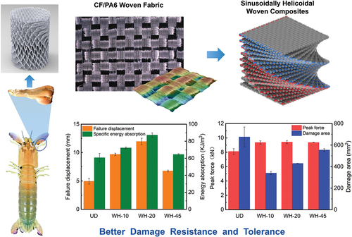
The impact region of the dactyl club of mantis shrimp features a rare sinusoidally helicoidal architecture, contributing to its efficient impact-resistant characteristics. This study aims to attain bioinspired sinusoidally architected composites from a practical engineering way. Morphological features of plain-woven fabric were characterized, which demonstrated that the interweaving warp and weft yarns exhibited a sinusoidal architecture. Interconnected woven composites were thus employed and helicoidally stacked to achieve the desired structure. Quasi-static three-point bending and low-velocity impact tests were subsequently performed to evaluate their mechanical performance. Under three-point bending condition, the dominant failure mode gradually changed from fiber breakage to delamination with the increase in the pitch angle. Failure displacement and energy absorption of the helicoidal woven composites were, respectively, 43.89% and 141.90% greater than the unidirectional ones. Under low-velocity impact condition, the damage area of the helicoidal woven composites decreased by 49.66% while the residual strength increased by 10.10% compared with those of the unidirectional ones, exhibiting better damage resistance and tolerance. Also, effects of fiber architecture on mechanical properties were examined. This work will shed light on future design of the next-generation impact-resistant architected composites.
GRAPHICAL ABSTRACT
1. Introduction
For decades, researchers have been working toward developing materials with improved mechanical properties, particularly with regard to increasing strength and toughness [Citation1–4]. Unfortunately, many studies have shown that increasing strength often comes at the expense of toughness, and vice versa. This relationship is often considered to be intrinsic and unavoidable, creating a trade-off between the two properties [Citation5,Citation6]. However, the limitation is broken by biological materials. The ingenious manner for biological materials to combine the organic and mineral components brings them multiscale and hierarchical microstructure, which leads to excellent mechanical performances both in strength and toughness [Citation7,Citation8], enlightening the design of superior engineering materials [Citation9–13].
Creatures have evolved various strong and tough biological materials to adapt to their environment. Some of them act as reliable armor to resist damage from their predators, such as fish scale [Citation14–16], nacre of pearl [Citation17,Citation18], beetle elytra [Citation19,Citation20], and mollusk shell [Citation21]. While although these protectors could be more than an order of magnitude tougher than their ceramic constituent, they can still be fractured by the predator (e.g. mantis shrimp) possessing the most powerful weapons [Citation22].
The peacock mantis shrimp (Odontodactylus scyllarus, ) boasts the fastest appendicular striker in the animal kingdom, with its stomatopod dactyl club () capable of reaching speeds of 14–23 m/s, peak accelerations of 65–104 km/s2 within an average period of 2.7 ms, and imposing instantaneous forces of over 1500 N without structural failure [Citation24,Citation25]. The dactyl club of the mantis shrimp is composed of three distinct regions, each with its own unique architecture: the impact, periodic, and striated regions [Citation26] as shown in . The impact region consists of highly oriented and crystalline fluorapatite nanorods surrounded by a thin protein – chitin organic matrix, featuring a fibrous herringbone-modified helicoidal architecture, which provides enhanced redistribution of excessive stress [Citation23,Citation27]. This region displays a quasi-plastic contact response, allowing the fluorapatite nanorods to slide and rotate under contact loading to dissipate potential damage under repetitive impacts [Citation28].
Figure 1. Morphological features of the stomatopod dactyl club and bio-inspired woven. (a) A generalized stomatopod body. (b) A magnified view of the club’s external morphology. (c) Optical microscopy of the impact surface, bulk impact region, and periodic region [Citation23]. (d) Schematics of the sinusoidally architected helicoidal structure of the impact region. (e) Surface morphology and (f) Three-dimensional contour measurement diagram of the dry plain-woven carbon fiber fabric. (g~i) Schematic of the plain-woven laminates with helicoidal configuration.
![Figure 1. Morphological features of the stomatopod dactyl club and bio-inspired woven. (a) A generalized stomatopod body. (b) A magnified view of the club’s external morphology. (c) Optical microscopy of the impact surface, bulk impact region, and periodic region [Citation23]. (d) Schematics of the sinusoidally architected helicoidal structure of the impact region. (e) Surface morphology and (f) Three-dimensional contour measurement diagram of the dry plain-woven carbon fiber fabric. (g~i) Schematic of the plain-woven laminates with helicoidal configuration.](/cms/asset/259efc9d-2ced-4e06-890c-af155519bce1/tsnm_a_2236572_f0001_c.jpg)
The present bio-inspired designs mainly focused on the Bouligand structure of the periodic region [Citation29,Citation30]. There are relatively limited studies on the sinusoidal-helicoidal structure of the impact region. Yaraghi et al. used dual-material printing technology to fabricate the bio-inspired composites, where the fibers were printed with a hard polymer and the matrix with a soft elastomer [Citation23]. Yang et al. proposed a novel double-sine corrugated sandwich structure that significantly improved structural crashworthiness [Citation31]. However, the preparation methods for the sinusoidal-helicoidal structure were not practical in terms of production efficiency and cost, limiting the engineering application of bio-inspired composites.
In this study, CF/PA6 plain-woven composites with helicoidal configurations, which were inspired by the impact region of the dactyl club of the mantis shrimp, were designed and prepared using the hot-press method. The morphological features of the plain-woven fabric were characterized to validate the bionic design. Quasi-static three-point bending and low-velocity impact tests were conducted to evaluate the flexural properties, damage resistance, and damage tolerance. The effect of the fiber architecture on the mechanical properties was also discussed.
2. Experimental
2.1 Bioinspired design
Different from the Bouligand architecture observed in the periodic region, the impact region of the dactyl club of mantis shrimp exhibited a sinusoidally helicoidal architecture, as geometrically illustrated in . Here, bioinspired engineering composites were imitated by the textile architecture of woven composites formed by the vertical intersection of warp and weft yarns. shows the optical micrographs of plain-woven fabric (taken by Keyence VHX-6000), where a periodic interweaving architecture with a sinusoidal profile of each yarn can be observed () [Citation32]. The amplitude of each yarn is ~260 μm, while the wavelength
is ~1350 μm, and thus the ideal model comprising interweaving sinusoidal fibers is shown in . The plain-woven fabric was then stacked up helicoidally, forming sinusoidally helicoidal composite laminates (). Three helicoidal sequences with 20 plies were designed with three different pitch angles including 10°, 20°, and 45°, comparing with the unidirectional laminated composites. Besides, to eliminate possible warping during the manufacturing process, all lay-up sequences were mid-plane symmetric as summarized in .
Table 1. Woven composite laminates with four types of stacking sequences.
2.2 Fabrication
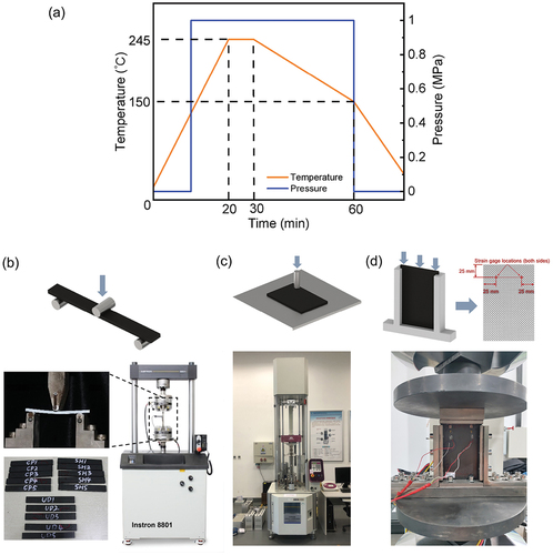
Plain-woven T300 carbon fiber reinforced polyamide 6 thermoplastic prepreg (Nanjing Valet Technology Co., Ltd.) with fiber volume fraction of 50% was selected as the raw material for bio-inspired composites. The prepreg was placed in a drying oven at 80◦C for 12 h to remove the moisture in the matrix and then cut into square pieces (120 × 120 mm) with specific angles by a laser cutting machine (Beijing Laser-Sino Technology Co., Ltd). All the pieces were stacked together and laid in a closed metal mold that could prevent resin from flowing out during curing. To shorten the heating time and prevent the prepreg from experiencing oxidation, we used a heating plate with high heating efficiency. The curing curves were obtained according to the manufacturer’s guidelines, where the prepregs were heated to 245°C in 20 min and then retained at a pressure of 1 MPa for 10 min () in a hot-press. After demolding, the laminates were machined into specified strips using an engraving machine.
Figure 2. Fabrication and mechanical testing methods. (a) Temperature and pressure curves for thermoplastic composites manufacturing. Tests setting of (b) three-point bending, (c) low-velocity impact, and (d) compressive residual strength test and the specific locations of strain gage.
2.3 Mechanical testing
2.3.1 Three-point bending tests
Quasi-static bending tests were performed in accordance with the ASTM Standard D7264. An Instron 8801 electro servo-hydraulic testing machine (Instron, Norwood, MA, U.S.A.) was utilized () at a loading rate of 2 mm/min. Tests were terminated when the load value dropped to 10% of the peak force value. Videos were recorded during the test using a digital camera (Canon, Japan) for further analysis. The overall dimensions of the bending specimens were designed to be 100 mm × 13 mm × 5 mm, with a span-to-thickness ratio of 16:1. At least three repeated tests were conducted for each type of specimens to ensure repeatability [Citation33].
2.3.2 Low-velocity impact tests
To evaluate the damage tolerance and resistance of the bio-inspired composites, drop-weight impact and compression after impact tests were performed. Drop-weight impact tests were performed following the procedure of ASTM D7136. An Instron CEAST 9350 machine was used for the test (). The impactor had a weight of 5.5 kg, and the impact energy E was calculated by , where
is the ratio of impact energy to specimen thickness and equals to 6.7J/mm here. The dimension of the specimen is 150 × 100 × 5 mm. Damaged specimens after impact were examined by nondestructive pulse-echo ultrasonic C-scans performed in a water tank using a 5 MHz transducer.
After the analysis of the impact, uniaxial compressions were performed according to the procedure of ASTM D7137 to characterize the residual strength properties of the laminates. The tests were employed using a 500 kN fatigue machine MTS-880 (). The damaged plate was installed in an aligned multi-piece support fixture to minimize loading eccentricities and induced specimen bending. The percent bending was calculated by , where
and
were the strain from the back-to-back strain gage that were set at the locations as shown in . The test results were acceptable only if the percent bending was kept to less than 10%. The compression was terminated when the load value decreased to 30% of the peak load. The residual strength was calculated by
, where
was the ultimate compressive residual strength,
was the maximum force prior to failure, and
was the cross-sectional area.
3. Results and discussion
3.1 Quasi-static flexural performance
The flexural properties of different configurations were compared in . All helicoidal woven configurations exhibited excellent toughness. The failure displacement of WH-10, WH-20, and WH-45 was 18.98%, 43.89%, and 6.61% higher than that of UD, and the energy absorption of WH-10, WH-20, and WH-45 was 95.95%, 141.90%, and 27.66% higher than that of UD. WH-20 exhibited the best performance among the helicoidal woven configurations, with an energy absorption of 87.2 kJ/m2 and failure displacement of 11.95 mm. However, the flexural stiffness and strength of UD were better than the helicoidal woven configurations, which reached 39.76 GPa and 600.06 MPa, respectively. Tensile tests of unidirectional configuration woven laminates have shown that the stiffness and strength of the laminates will decrease but the elongation at break will increase when the fiber orientation deviates from the direction of tensile (0–45°). When the woven laminates were loaded in three-point bending conditions, laminates with more 0° and 90° plies near the bottom and top surface would exhibit greater flexural stiffness and strength but worse toughness, which explains the test result since UD and WH-45 configurations have higher percentage of 0° and 90° plies.
Figure 3. Comparison of flexural properties for different configurations: (a) Flexural stiffness and strength and (b) failure displacement and energy absorption. The corresponding deformation history accompanying with the failure modes for (c) UD, (d) WH-10, (e) WH-20, and (f) WH-45.
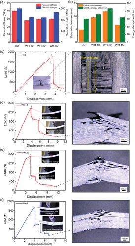
The deformation history along with the representative failure modes are summarized and shown in ~3f. For all configurations, cracks initiated from the tensile side were the main reason for the catastrophic failure, while the cracks on the compression side propagated stably. Hence, the crack on the compression side would not substantially influence the failure process, and the failure on the tensile side should be mainly focused on in afterward investigation.
As shown in , the load–displacement curves of UD were obviously elastic-brittle. When the load slightly decreased before the peak value, a cracking sound was emitted inside the sample, but no visible damage was observed outside. It was speculated that the fiber might be broken at this time. The specimen failed catastrophically at point I. Optical micrographs of the damaged specimen showed that fiber breakage on the tensile side was the dominant failure mode of UD.
For WH-10 in , no visible damage and load drop could be observed before the peak force. When the load dropped initially at point I, except for slight fiber breakage at the bottom surface, no other damage could be observed. Hence, the specimen was still load-carrying, and its load–displacement curve then enters the smooth platform stage. The in-situ micrograph photo at the second load drop (point II) showed that the translaminar crack began to propagate from the bottom to the mid-plane and a small amount of delamination near the bottom surface could be observed. The dominant failure mode of WH-10 was a translaminar crack.
For WH-20 in , an obvious stiffness degradation stage before the peak force could be observed, where slight fibers broke in the compression side. The first load drop at point II was caused by the delamination on the tensile side and fiber breakage. The delamination and crack then further expanded until the specimen lost carrying capacity. The final failure mode was shown in the right figure. Obvious damage occurred on both the tensile side and the compression side: fiber fracture mainly occurred on the compression side, while fiber fracture and delamination mainly occurred on the tensile side.
For WH-45 in , no stiffness degradation or damage could be observed. The load dropped for the first time at point I, at which point fiber breakage occurred, and simultaneously delamination occurred at the interface near the lower surface. The second load drop at point II was due to the delamination of more interfaces on the tensile side. The final failure mode of WH-45 had a larger area of delamination with multiple interfaces compared with other helicoidal woven configurations.
From the failure modes of different configurations, it can be summarized that with the increase in the pitch angle for three helicoidal woven configurations, the dominant failure mode transitioned from a translaminar crack to multiple delamination. Because of the minimum interlaminar shear stress, delamination did not occur for UD.
3.2 Drop-weight test and damage resistance
The load–displacement curves for drop-weight are shown in . The curve could be divided into three stages, as illustrated in : the load rising stage (Stage I); the oscillation stage (Stage II) when the load oscillated violently with load displacement; and the load descent stage (Stage III) when the laminate broke or the impactor rebounded. Considering the damage in three stages, matrix cracks occurred in the late Stage I, and the load growth slowed down; then delamination and fiber breakage occurred during Stage II. Because of the limited impact energy, all laminates were not penetrated and the impactor rebounded. Curves in stage II were magnified and smoothed using a Savitzky-Golay smoothing method to make the curves easier to understand [Citation34]. It should be noted that the smoothed curves cannot present an accurate value of the actual forces during the impact but give a clear exhibition about the average level and the trend of the load.
Figure 4. Experimental results of drop-weight impact: (a) Load–displacement curves; (b) three stages of the load–displacement curve. (c) Comparison of peak force and damage area. Ultrasonic C-scan images showing damage in the (d) UD, (e) WH-10, (f) WH-20, and (g) WH-45.
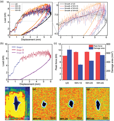
The damage resistance was quantified in terms of the peak force during tests and damage area measured from ultrasonic C-scan images, and the results have been summarized in . With the same ratio of impact energy and laminate thickness, all three helicoidal woven configurations (WH-10, WH-20, and WH-45) exhibited excellent damage resistance, whose peak force was 15.51%, 16.21%, and 15.52% higher than UD, respectively. Besides, the intrusion depth (the displacement of the impactor when the velocity of the impactor was zero) of the three helicoidal woven configurations was lower than that of the UD. The peak loads of the three helicoidal woven configurations were similar, but the intrusion depth of WH-45 was the lowest, and the load in Stage II of WH-45 was higher than that of WH-10 and WH-20. The difference in load–displacement curves between WH-10 and WH-20 was not obvious.
The ultrasonic C-scan images of all configurations are shown in ~4 g. The damaged area was the blue area enclosed by the white line. It can be seen that the damage extent of UD was more severe than that of three helicoidal woven configurations. The damaged area of WH-10, WH-20, and WH-45 was 49.66%, 36.43%, and 18.02% smaller than UD. With the decrease in the pitch angle (WH-45 to WH-10), the damaged area decreased and the anisotropy of the damage was alleviated. The damage shape of UD shows the most anisotropy, where the damaged area was mainly distributed along the vertical direction. The damage shape of WH-45 was the most anisotropic among the three helicoidal woven configurations, which exhibited a narrow oval with vertical distribution. The damage shape of WH-20 was more uniform than that of WH-45 but still presents a certain orientation to the vertical direction. The damaged shape of WH-10 was almost circular, showing the best uniformity in all directions.
The above experimental results showed that the helicoidal woven configurations had excellent damage resistance. Compared with the unidirectional configuration commonly used in engineering, helicoidal woven configurations exhibited higher peak load under low-speed impact and much smaller damaged area. What is more, the distinctive configuration reduced the anisotropy of the laminated fabric and made the damage distribution more uniform, which further improved the damage resistance.
3.3 Residual strength properties and damage tolerance
The percent bending and final failure mode were monitored to insure the validation of test results. The percent bending was kept to less than 10% during the test, which proved that the panel instability and excessive bending did not occur. The failure modes of all configurations are shown in
Figure 5. Experimental results of compressive residual strength tests: (a) Load–displacement curves. (b) Comparison of residual strength for different configurations. Compressive residual strength failure modes of (c) UD, (d) WH-10, (e) WH-20, and (f) WH-45. Effects of pitch angle on (g) flexural properties and (h) damage resistance and tolerance.
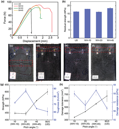
The typical load–displacement curves of uniaxial compression tests are shown in . For UD, although it showed the best compressive stiffness at the initial loading stage, its failure displacement and peak load were the lowest. Woven helicoidal configurations could withstand larger deformation and have higher peak load than UD configuration. WH-10 performed the best for having about twice the failure displacement of UD and maintaining high load level during compression. The residual compressive strengths are compared in . The residual compressive strength of WH-10 and WH-45 was 10.10% and 12.64% higher than that of the UD configuration. Referring to the results of three-point bending tests, the compression strength of undamaged UD configuration is supposed to be greater than that of helicoidal woven configurations, which highlighted the improvement in the damage tolerance introduced by helicoidal woven configuration.
3.4 Effects of the fiber architecture
3.4.1 Pitch angle
The pitch angle is a critical design factor for helicoidal structure, which affected the internal stiffness and failure mode. The pitch angle in plain-woven fabric ranged from 0° to 45° (pitch angle of the UD configuration could be considered as 0°). The relationship between flexural properties and pitch angle is shown in . Flexural strength and stiffness were related to the proportion of layer in the direction of 0° near the sample surface. As the pitch angle increased from 0° to 20°, the proportion of the 0° layer decreased, causing a decrease in bending strength and stiffness. When the pitch angle further increased to 45°, the proportion of the 0° layer increased, resulting in an increase in strength and stiffness. The energy absorption did not vary monotonously with pitch angle, and WH-20 exhibited the best energy absorption capacity, which was mainly related to the failure mode of laminates. The smaller the pitch angle, the greater the proportion of fiber breakage damage, with an increased stiffness and strength while decreased failure displacement. Conversely, a larger pitch angle led to a greater proportion of delamination failure, with a decreased stiffness and strength while increased failure displacement. For composite laminates, a combined failure modes of fiber breakage and delamination were an optimum mode for energy absorption, balancing the strength and failure displacement. Therefore, the energy absorption of WH-20 performed best.
The relationship between mechanical properties and pitch angle under low-velocity impact is shown in . The damage resistance was quantified in terms of the damaged area. Except for the UD configuration, with the increase in pitch angle (10° to 45°), the mechanical anisotropy of the laminates increased, and the damage resistance improved.
3.4.2 Woven features of fibers
Comparing the flexural properties of the woven helicoidal configuration with that of the non-woven helicoidal laminates and double-helicoidal laminates in our previous study [Citation35] (), it was observed that the failure displacements of the woven helicoidal configuration were much smaller resulting in a lower energy absorption capacity.
Table 2. Summary of the properties of non-woven (SH-10, SH-20, DH-10, and DH-20) and woven composites with helicoidal configurations.
The decrease in performance can be attributed to the difference in the way crack propagates. For non-woven helicoidal laminates, the primary toughening mechanisms introduced by helicoidal fibers are the twisting crack, where the crack tends to propagate through the breakage of the weaker part of the composites, which typically exhibits as the fracture of the matrix parallel to the fibers, and therefore is directed by the helicoidal ranked fibers. The consequent crack twisting significantly elongates the propagation path of the crack and enlarges the area of the crack, which effectively delays the catastrophic failure and increases the dissipated energy. In contrast, breakage parallel to the fibers is hindered by the vertical fibers in the woven helicoidal configuration. As a result, the crack cannot propagate in an ideal twisty manner, and the toughening introduced by the microstructure is therefore not comparable to that of the non-woven helicoidal laminates.
However, despite this fact, woven helicoidal configuration laminates still have better toughness than unidirectional laminates. The additional energy dissipation is considered to be brought by the damage caused by the shear of waft and weft fibers during the deformation. Taking advantage of the woven arrangement to manipulate the crack propagation could be the key factor to further improve the toughness, which will be the focus of our future research.
4. Conclusion
Inspired by the architecture of the impact region of the mantis shrimp’s dactyl club, composites with sinusoidal-helicoidal configuration were fabricated with CF/PA6 plain-woven prepreg possessing sinusoidal-shaped interweaving warp and weft yarns. The flexural properties were characterized by three-point bending tests, which showed that the failure displacement and energy absorption of the three helicoidal woven configurations were better than that of the unidirectional configuration. The pitch angle influenced the failure mode, with an increase in pitch angle resulting in a change from fiber breakage to delamination and a decrease in strength, but an increase in failure displacement. The best toughness was observed in the WH-20 configuration, with a mixture of fiber breakage and delamination failure modes.
Under low-velocity impact, the peak load and damaged area of the three helicoidal woven configurations were, respectively, higher and smaller than those of the unidirectional configuration, indicating excellent damage resistance. The residual compressive testing results showed that the failure displacement and residual compressive strength of helicoidal woven configurations were better, and the damage tolerance was improved. The anisotropy of the in-plane mechanical properties gradually increased with pitch angle, resulting in an increased damaged area and damage resistance. These results provide insights for designing high-damage-tolerant composites and broaden the designability of advanced composite materials by employing architectures.
Acknowledgments
This work was supported by the Natural Science Foundation of China (Grant No. 12172025), the Science Foundation of National Key Laboratory of Science and Technology on Advanced Composites in Special Environments (No. 6142905222707), the Fundamental Research Funds for the Central Universities, Beihang University, and BUAA-CAIP Lightweight Research Institute supported by Jiangsu Changshu Automotive Trim Group Co., Ltd.
Disclosure statement
No potential conflict of interest was reported by the authors.
Additional information
Funding
References
- Ashby MF, Gibson L, Wegst U, et al. The mechanical properties of natural materials. I. Material property charts. Proc R Soc Lond A. 1995;450(1938):123–140. doi:10.1098/rspa.1995.0075.
- Espinosa HD, Rim JE, Barthelat F, et al. Merger of structure and material in nacre and bone–perspectives on de novo biomimetic materials. Prog Mater Sci. 2009;54(8):1059–1100. doi:10.1016/j.pmatsci.2009.05.001
- Gao W, Zhang Y, Ramanujan D, et al. The status, challenges, and future of additive manufacturing in engineering. Comput Aided Des. 2015;69:65–89. doi:10.1016/j.cad.2015.04.001
- Fratzl P, Gupta H, Paschalis E, et al. Structure and mechanical quality of the collagen–mineral nano-composite in bone. J Mater Chem. 2004;14(14):2115–2123. doi:10.1039/B402005G
- Rühle M, Evans AG. High toughness ceramics and ceramic composites. Prog Mater Sci. 1989;33(2):85–167. doi:10.1016/0079-6425(89)90005-4
- Ritchie RO. The conflicts between strength and toughness. Nat Mater. 2011;10(11):817–822. doi:10.1038/nmat3115
- Dunlop JW, Fratzl P. Biological composites. Ann Rev Mater Res. 2010;40(1):1–24. doi:10.1146/annurev-matsci-070909-104421
- Meyers MA, Chen P-Y, Lin A-M, et al. Biological materials: Structure and mechanical properties. Prog Mater Sci. 2008;53(1):1–206. doi:10.1016/j.pmatsci.2007.05.002
- Huang W, Restrepo D, Jung JY, et al. Multiscale toughening mechanisms in biological materials and bioinspired designs. Adv Mater. 2019;31(43):e1901561. doi:10.1002/adma.201901561
- Chen Q, Pugno NM. Bio-mimetic mechanisms of natural hierarchical materials: A review. J Mech Behav Biomed Mater. 2013;19:3–33. doi:10.1016/j.jmbbm.2012.10.012
- Zhang C, Mcadams DA, Grunlan JC. Nano/micro-manufacturing of bioinspired materials: A review of methods to mimic natural structures. Adv Mater. 2016;28(30):6292–6321. doi:10.1002/adma.201505555
- Ha NS, Lu G. A review of recent research on bio-inspired structures and materials for energy absorption applications. Compos B Eng. 2019;181:107496. doi:10.1016/j.compositesb.2019.107496
- Maghsoudi-Ganjeh M, Lin L, Wang X, et al. Bioinspired design of hybrid composite materials. Int J Smart Nano Mat. 2018;10(1):90–105. doi:10.1080/19475411.2018.1541145
- Quan H, Yang W, Schaible E, et al. Novel defense mechanisms in the armor of the scales of the “living fossil” coelacanth fish. Adv Funct Mater. 2018;28(46):1804237. doi:10.1002/adfm.201804237
- Yin S, Yang R, Huang Y, et al. Toughening mechanism of coelacanth-fish-inspired double-helicoidal composites. Compos Sci Tech. 2021;205:108650. doi:10.1016/j.compscitech.2021.108650
- Yang W, Quan H, Meyers MA, et al. Arapaima fish scale: One of the toughest flexible biological materials. Matter. 2019;1(6):1557–1566. doi:10.1016/j.matt.2019.09.014
- Oaki Y, Imai H. The hierarchical architecture of nacre and its mimetic material. Angew Chem Int Ed Engl. 2005;44(40):6571–6575. doi:10.1002/anie.200500338
- Barthelat F, Espinosa HD. An experimental investigation of deformation and fracture of nacre–mother of pearl. Exp Mech. 2007;47(3):311–324. doi:10.1007/s11340-007-9040-1
- Rivera J, Hosseini MS, Restrepo D, et al. Toughening mechanisms of the elytra of the diabolical ironclad beetle. Nature. 2020;586(7830):543–548. doi:10.1038/s41586-020-2813-8
- Zaheri A, Fenner JS, Russell BP, et al. Revealing the mechanics of helicoidal composites through additive manufacturing and beetle developmental stage analysis. Adv Funct Mater. 2018;28(33):1803073. doi:10.1002/adfm.201803073
- Li L, Ortiz C. Pervasive nanoscale deformation twinning as a catalyst for efficient energy dissipation in a bioceramic armour. Nat Mater. 2014;13(5):501–507. doi:10.1038/nmat3920
- Wegst UG, Bai H, Saiz E, et al. Bioinspired structural materials. Nat Mater. 2015;14(1):23–36. doi:10.1038/nmat4089
- Yaraghi NA, Guarin-Zapata N, Grunenfelder LK, et al. A sinusoidally architected helicoidal biocomposite. Adv Mater. 2016;28(32):6835–6844. doi:10.1002/adma.201600786
- Patek SN, Korff W, Caldwell RL. Deadly strike mechanism of a mantis shrimp. Nature. 2004;428(6985):819–820. doi:10.1038/428819a
- Patek SN, Caldwell RL. Extreme impact and cavitation forces of a biological hammer: Strike forces of the peacock mantis shrimp odontodactylus scyllarus. J Exp Biol. 2005;208(Pt 19):3655–3664. doi:10.1242/jeb.01831
- Weaver JC, Milliron GW, Miserez A, et al. The stomatopod dactyl club: A formidable damage-tolerant biological hammer. Science. 2012;336(6086):1275–1280. doi:10.1126/science.1218764
- Huang W, Shishehbor M, Guarin-Zapata N, et al. A natural impact-resistant bicontinuous composite nanoparticle coating. Nat Mater. 2020;19(11):1236–1243. doi:10.1038/s41563-020-0768-7
- Amini S, Tadayon M, Idapalapati S, et al. The role of quasi-plasticity in the extreme contact damage tolerance of the stomatopod dactyl club. Nat Mater. 2015;14(9):943–950. doi:10.1038/nmat4309
- Wang K, Wu X, An L, et al. Crack modes and toughening mechanism of a bioinspired helicoidal recursive composite with nonlinear recursive rotation angle-based layups. J Mech Behav Biomed Mater. 2023;142:105866. doi:10.1016/j.jmbbm.2023.105866
- Luo H, Wang H, Zhao Z, et al. Experimental and numerical investigation on the failure behavior of bouligand laminates under off-axis open-hole tensile loading. Compos Struct. 2023;313:313. doi:10.1016/j.compstruct.2023.116932
- Yang X, Ma J, Shi Y, et al. Crashworthiness investigation of the bio-inspired bi-directionally corrugated core sandwich panel under quasi-static crushing load. Mater Des. 2017;135:275–290. doi:10.1016/j.matdes.2017.09.040
- Yao Y, Dou H, Liu T, et al. Micro- and nano-scale mechanisms of enzymatic treatment on the interfacial behaviors of sisal fiber reinforced bio-based epoxy resin. Ind Crop Prod. 2023;194:116319. doi:10.1016/j.indcrop.2023.116319
- Kang J, Liu T, Lu Y, et al. Polyvinylidene fluoride piezoelectric yarn for real-time damage monitoring of advanced 3d textile composites. Compos B Eng. 2022; 245:110229. doi:10.1016/j.compositesb.2022.110229
- Li H, Chen W, Hao H. Factors influencing impact force profile and measurement accuracy in drop weight impact tests. Int J Impact Eng. 2020;145:145. doi:10.1016/j.ijimpeng.2020.103688
- Yin S, Yang R, Huang Y, et al. Toughening mechanism of coelacanth-fish-inspired double-helicoidal composites. Compos Sci Technol. 2021;205:108650. doi:10.1016/j.compscitech.2021.108650