ABSTRACT
We present a methodology to use a UAV (unmanned aerial vehicle) to perform photogrammetric surveys and detailed geological mapping in mountain areas. This work is specially related to the presented case study with the aim to realize geomorphological maps from UAVs, since they can house different types of sensors and acquire data more rapidly and cheaply than traditional geological surveys directly obtained with field observations. This work explains how UAVs can obtain digital terrain models, orthophotos and 3D models in order to create slope and aspect maps for geological purposes. By integrating data from UAVs with geological surveys made on the field, geological maps can be produced where many of the geological elements are presented. This paper presents the integration of geomatics and geological techniques.
Starting from UAV slope map and orthophotos, a new geological map was created in a faster and more detailed way compared to traditional geological survey on the ground. The application of this method regards a sector of the Western Alps (NW Italy), formed by glaciers and deep-seated gravitational slope deformations.
1. Introduction
Geological mapping is a complex and time-consuming activity, especially when carried out in mountain areas, where there are high slopes (Fischer et al. Citation2012; Joyce et al. Citation2014). Although expert geologists can carry out ground mapping, they do not always achieve a complete overview of the area. Moreover, such ‘traditional mapping’ (geological survey: lithological formation, structural and geomorphological elements, etc.) does not investigate all the properties of the terrain, such as any water content.
On the other hand, by covering a large area in very short time (ca. 60 ha/h), unmanned aerial vehicles (UAVs) can acquire data more rapidly and less expensively than typical airborne surveys. Commercial UAVs (Sadeghipoor et al. Citation2015) typically acquire RGB (Endres et al. Citation2014) and near-infrared (NIR) images (Chen et al. Citation2015). Using a photogrammetric approach, digital surface models (DSMs), digital terrain models (DTMs) (Dabove et al. Citation2015) and orthophotos (Guarnieri et al. Citation2015) can be generated automatically. Slope and aspect maps can also be extracted from DTMs, which are useful for examining the area and extracting the geological map.
The final products provide geologists with a more complete and extended point of view, which can then be used to verify the quality and validity of data collected in the field using traditional surveys.
The geological information collected by traditional geological mapping obtained in the field is used to compare the same information which is identified by these maps. Currently, many cartographic geological products are obtained by coupling satellite images (often with low resolution) and field surveys, which is time-consuming and requires very accurate knowledge of the land area.
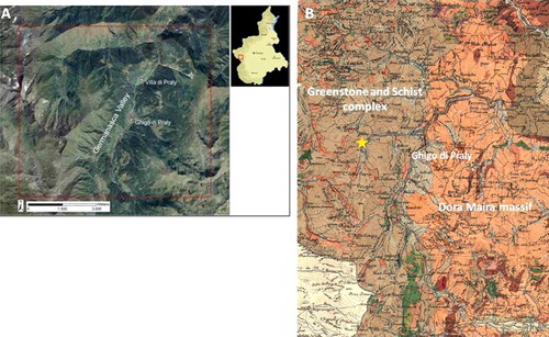
Geological research with UAVs is carried out all over the world, and exploiting UAVs for geological applications is common. In fact, UAVs have reduced the time of geological surveys, while maintaining the quality of details (Bemis et al. Citation2014). UAVs are often used for regional research such as territory analysis (Farfaglia et al. Citation2015), landslide monitoring (Torrero et al. Citation2015), deformation analysis (Shi & Liu Citation2015), mapping geological structures at a small scale (Vasuki et al. Citation2014), and also for monitoring geothermal environments (Nishar et al. Citation2016). However, to the best of our knowledge, UAVs have not been employed for detailed geological surveys. We used a UAV to map a sector of the Rodoretto Valley, a left tributary of the Germanasca Valley, located in the Western Alps (NW Italy) on the Greenstone and Schist (GS) Complex of the Penninic Domain (). The area investigated was formed by glaciers and deep-seated gravitational slope deformations.
Figure 1. Aerial image of the study area (A) and western geological map modified by Mattirolo et al. (Citation1913) (B), where the star represents the study area.
2. Geological setting
A sector of the Rodoretto Valley, a tributary of the Germanasca Valley, NW Alps, Italy, was analyzed and a detailed morphological definition of the glacial and gravitational sediments and landforms via remote sensing was produced (Taddia et al. Citation2015).
The Rodoretto Valley is located in the GS Complex of the Penninic Domain, near the N–S tectonic discontinuity with the Dora Maira Massif (DM) (). This area is crossed by the Cenischia-Nizza system, a N–S regional system of fractures.
The distribution of the Quaternary glacial sediments and landforms indicates the presence of a glacier, marked by different advance and retreat stages (Forno et al. Citation2011). The entire Rodoretto Valley is also involved in deep-seated gravitational slope deformation (DSGSD), developed after and during the glacial shaping (Forno et al. Citation2011, Citation2013). The main elements of the landscape, preserved on the valley floor and on the mountain sides, are many glacial valley relicts and moraines, both with glacial sediments, minor scarps, trenches and landslide niches and accumulations connected to DSGSD. There are also more recent alluvial and avalanche scarps connected to incisions.
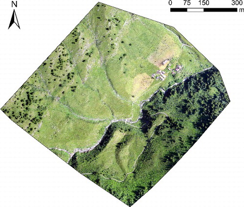
Various geomatics techniques were considered in order to investigate a sector of the Rodoretto Valley and to produce a detailed morphological definition of the glacial and gravitational sediments and landforms. A UAV was used to generate the DSM, and some terrestrial surveys with total station and GNSS instruments were performed for georeferencing images.
3. Description of the procedure and geomatics activities
As described in Eisenbeiss (Citation2009), two aspects must be considered before carrying out an aerial acquisition using UAV: the choice of the acquisition system and the data-processing strategy, which are fundamental for the image overlap and the expected ground sample distance (GSD).
The choice of the acquisition system (fixed-winged or multi-rotor UAV) depends on the type of activity that will be made, since they have different performances in terms of payload, flight time and stability in data acquisition. For example, for photogrammetric purposes, a fixed-wing UAV is preferable in wide areas (1.5 km radius), while multi-rotor UAVs are more suitable for smaller areas (400 × 400m) or where vertical flight is required (Giordan et al. Citation2015).
The data-processing strategy should take into account planning the flight, defining the survey area, the number of lines and the relative flight altitude.
Data acquisition is key because it includes not only flights but also measuring the vertex of the reference network through a topographic (total station or GNSS) survey and the determination of ground control points (which are used for the georeferencing – Chiabrando et al. Citation2013). The final stage is data processing, which includes photogrammetric triangulation (image alignment for the 3D point cloud generation), 3D model reconstruction, the DSM and orthophotos extraction, and data integration.
Before starting the flight procedures, first, the ground surveys need to be analyzed. In order to define the coordinates of the ground control points that were used to georeference the orthophotos and DSM, we created and measured a geodetic network by using both GNSS and traditional topographic (total station) surveys.
The GNSS campaign was conducted using double frequency and multi-constellation receivers and considering both a post-processing (Dabove et al. Citation2014) and an RTK (real-time kinematic, with radio connection for real-time corrections) approaches, due to the lack of the GSM signal. Thus, a master station was set up (for a session length of more than four hours) on a point that was named GPS1 in order to have a known point with millimetrical precision. This point was then used to adjust the other markers.
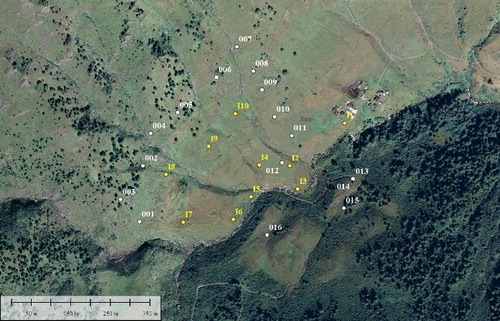
The coordinates of this station were determined by a post-processing approach, considering a single-base solution (obtained with the Leica Geo Office v.8.4, Leica Geosystems®) with a Virtual RINEX created by the continuous operating reference stations (CORSs) of the Piedmont regional government (Dabove & Manzino Citation2014). An RTK survey with radio connection was then made in order to estimate markers with no leaf coverage (prefix 0 in ), considering a session length of about 10 s for each point. The coordinates were estimated with a centimetre accuracy (σ = 3 cm) with fixed-phase ambiguities for all points, which ensured a high level of precision for the georeferencing process. In some cases, where the leaf coverage was extremely high, target points were measured by traditional topographic instruments (prefix I in ). In this case, the total station was set on the tripod of the GNSS master station (point GPS1) in order to measure all the remaining markers, thanks to a reflector. All the measurements were subsequently adjusted (following the minimum constraints approach) with MicroSurvey StarNet v.7.0, in order to obtain the final coordinates of the GCPs (ground control points): the root mean square (RMS) obtained with StarNet is less than 1 cm.
Figure 2. Points acquired by GNSS (with prefix 0) and total station (with prefix I) instruments obtained after the post-processing.
The ellipsoidal heights measured with GNSS instruments were converted into orthometric heights using a local geoid model (ITALGEO2005) provided by the Italian Military Geographical Institute. To do this, the .GK2 grids and CartLab software were used (Dabove et al. Citation2014).
These points were then used to georeference the 3D model which was obtained considering the photogrammetric solution.
3.1. UAV flight with RGB camera
The resolution of the model or the data update sometimes entails integrating the map with additional data, both aerial and terrestrial. UAVs can be now used to acquire aerial information (RGB, multispectral, NIR images) in order to create 3D models and to make a land classification.
It is essential to choose the best solution in relation to the specific case study (Boccardo et al. Citation2015). For this application, due to the large area involved and the ground shape, we use an eBee, which is a commercial fixed-wings solution made by Sensefly. An eBee can fly for up to 40 minutes, with a coverage of 35–40 ha and it does not require a runway or expert users, because take-off and landing are completely automatic.
The main technical and operational characteristics of this system are reported in
Table 1. Main characteristics of the fixed-wing UAV employed.
The photogrammetric acquisitions with the eBee were carried out through an RGB Canon IXUS 110 (12.1 Mp, 1.33 µm of pixel size).
Using eMotion software, the flight was planned considering a photogrammetric overlap between images of 80% in the lateral and longitudinal direction, and a coverage of about 37 ha of ground.
To have a constant ground resolution of 4 cm, the RGB flight was made at an altitude of 130 m (21 strips, 276 images and 22 minutes of flight), and it was planned using a DTM that the software uses (Google Satellite) to navigate along the altitude. It is also possible to use one's own DTM or orthophoto in the planning stage.
The take-off and landing settings are crucial since the UAV lands by itself. Our tests showed that, thanks to the internal GNSS and ultrasound proximity sensors, the eBee can land in the defined area with an accuracy of about 5 m. In the specific case of the Rodoretto Valley, due to a changing GNSS coverage during the flights, some landing problems were found that were solved by using remote control.
The eBee has its own navigation sensors that perform the flight through the waypoints generated during the planning phase. Using these sensors, during the flight, the eBee also records the position of acquisition of each photo, which can then be used to geotag the images.
4. 3D model generation and data integration
The aim of the photogrammetric acquisition was to produce an orthophoto and a dense DSM (DDSM) with a high resolution (4 cm) in order to integrate the existing spatial data to perform geological mapping.
All the acquired images were post-processed using a structure from motion (SFM) approach (Turner et al. Citation2012) to rapidly and accurately extract a 3D model from images (Westoby et al. Citation2012). In this case, the processing was performed using two different commercial solutions (Mendes et al. Citation2015):
Menci APS (Automatic Photogrammetric Station): which is an image processing software application for mapping and modelling, and which comes with the eBee (http://www.menci.com/photogrammetry-software/aps-3d-maps-software);
Agisoft PhotoScan: this is one of the most popular commercial solutions for 3D reconstructions starting from digital images (http://www.agisoft.com/).
Both these software applications follow a specific workflow for generating the model (Remondino et al. Citation2014):
image alignment and point cloud generation: this defines the position of the image in a local coordinates system starting from the tie points extraction (usually through the SIFT operator). It generates a sparse point cloud (Aicardi et al. Citation2014);
3D coloured model: starting from the point cloud, a triangulated irregular network (TIN) mesh is generated;
model georeferencing: with both applications, the model can be georeferenced in a chosen reference system; this is possible through the use of approximate external orientation parameters acquired by the UAV during the flight or through targets (GCPs) to improve the accuracy. In this case, we use the second method, in which some points were used also for the model validation. In particular, five of them were used as control points showing a final accuracy of about 5 cm;
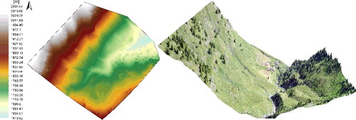
generation of photogrammetric products: a DDSM () and an orthophoto () are generated. They are coloured, georeferenced and with a resolution of 4 cm (Teeravech Citation2015).
In , the shape of the area was highlighted using the ArcGis scene exaggeration tool (factor 2), which gives a 3D display of the tree elevation.
The photogrammetric acquisitions are used to create a surface model that includes trees and buildings. In order to perform analyses regarding the ground conformation, it is essential to filter this information and obtain a DTM. PhotoScan is then used to classify the ground points, and APS performs a filtering using preselected scenarios.
The classification can be performed in PhotoScan with a manual or an automatic approach. With the manual approach, the user can select points and assign to them a specific class. Otherwise, the automatic classification procedure consists of two steps:
- first, the dense cloud is divided into cells and the lowest point is detected. Triangulation of these points gives the first approximation of the terrain model;
- then, new point is added to the ground class, providing that it satisfies two conditions: it lies within a certain distance from the terrain model and that the angle between the terrain model and the line to connect this new point with a point from a ground class is less than a certain angle. The second step is repeated while there are still points to be checked.
Instead, the APS solution uses the automatic filtering which allows to remove elevation points according to pre-defined scenarios (country, suburban, urban and metropolitan) and a curvature threshold that defines if the point can be considered ground or not.
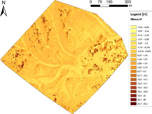
Both approaches were tested and APS gave the best results, since PhotoScan did not filter out all the trees. highlights the differences between the DSM and the DTM, where all the trees were filtered.
Figure 5. Differences between the DSM and the DTM of Prali: the DTM was generated by filtering the DSM in the APS software.
For the environmental analysis, several products were generated in order to integrate the 3D model information with the new geological surveys.
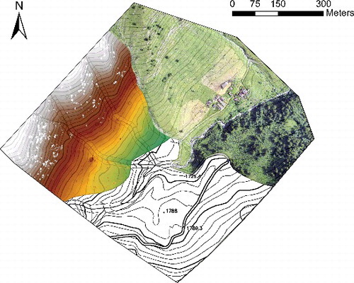
In addition to the DSM, the DTM, the orthophoto and the technical map (), the slopes and the contour were extracted. On the basis of the DTM, the Spatial Analyst toolbox of ArcGis was used to generate the slopes and contours.
The main part of the processing is the integration of this information into the geological mapping. Geological mapping involves many types of information, from analytical data to subjective observations, for example, in this case, various geological elements as glacial landforms (moraines, cirques and glacial limbs), gravitative landforms (landslides, minor scarps, trenches, fractures, detachment niches and landslide accumulations), structural elements (minor scarps, and faults), torrential and avalanche incisions collected and synthesized by a researcher. The geologists generally develop effective personal styles of relatively efficient mapping during field experience (Athey et al. Citation2008). Each geological map, regardless of scale, requires a certain level of field mapping, where data are recorded on a topographic plot, on aerial photographs and in a field book. Traditionally, geological elements are hand-transferred to a topographic base, on which the final map is prepared for publication using known cartographic techniques (Brown & Sprinkel Citation2008; Forno et al. Citation2013). In particular, to better understand the geological mapping, it can be combined with:
- the behaviour of the slope;
- a technical map ();
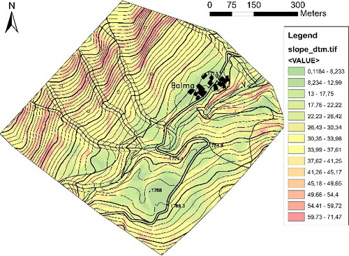
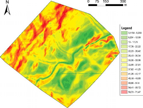
- the slope map ().
Figure 8. Slope map of the area: different inclinations are shown in gray as reported in the legend.
Finally, the use of a solid (true) Orthophoto (Forno et al. Citation2012) provides a complete 3-D land data interface and a correct aerial photographic perspective in a geo-referenced form, which on site, during the survey, were very useful (Forno et al. Citation2011).
Geologists unskilled in geomatics have efficiently used these new instruments during field surveys. The 3-D visualization facilitated the immediate interpretation of relict landforms with:
time savings during acquisition and loading into GIS software;
fewer errors thus obviating the need for repeated reconnaissance and which also speeds up map productions;
better understanding of the morphological evidence with the availability of 3D geometric information integrated with 2D views similar to what the surveyor sees.
5. Analysis of the models and results
The described methodology with UAV was applied in the investigated area to evaluate whether this approach could help the geological survey, thus allowing us to build a wider application model.
The slope map can furnish information for representing morphological and geological evidence. The possibility of using this representation is strictly conditioned by previous geological surveys of the area, which means that the various slope changes can be referred to a typical geological context. Most of the geological interpretations are also supported by the observations of orthophoto and DSM derived from aerial photos taken during the flight and also slope maps generated from them. This means that the recognized slope changes can be read, which is particularly useful in the largely inaccessible areas.
The case study was a glacial valley with steep rocky mountain sides and a wide flat valley floor covered with subglacial and supraglacial sediments. The gravitational phenomena involving this area are clear from many gravitational elements, such as fractures, minor scarps and trenches (Forno et al. Citation2012). The produced slope map covers a sector of the left slope (northern area in ) and the wide valley floor (southern area in ). The detailed geologic knowledge of the area allowed us to univocally read the slope map.
An overall interpretation of the slope map helps to understand the distribution of the bedrock and Quaternary sediments. Steep sectors visible in this map () correspond to rock outcrops on the left side, because only the bedrock creates sharp walls. The flat sectors () correspond to the areas covered by glacial sediments, on the wide valley floor. The medium slope sectors () correspond to the mountain side and valley floor areas without bedrock outcrops but covered by thin colluvium.
A more detailed interpretation of the slope map can, in addition to overall observations, help to map the linear geological elements showing an immediate morphological response ().
Figure 9. Morphological and Quaternary geological map of the Rodoretto Valley. 1: minor scarp; 2: trench; 3: scarp connected to torrential incision; 4: torrential incision reused by avalanche phenomena; 5: avalanche fan; 6: detachment niche; 7: landslide accumulation limit; 8: moraine axis; 9: outwash incision.
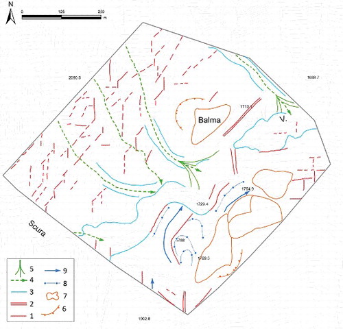
In detail, the steep sectors highlighted in the slope map indicate the occurrence of minor scarps (1 in ), which stand out from the other morphological elements. The scarps observed on the left side of the mountain, around two main directions N50° and N–S, form typical rock walls with an articulated setting, resulting from the intersection of the two systems. The N50° fractures prevalently cut the other surfaces. The scarps observed in the valley floor, most of which are oriented N50°, involve the bedrock and the Quaternary cover. These gravitational landforms are clear from the vertical dislocation of the glacial valley floor relicts. Some relatively flat sectors, generally narrow and elongated following the main fracture (N50° and N–S), sometimes indicate trenches (2 in ). The trenches located in the valley floor appear to have been enlarged by glacier or a watercourse.
The slope map shows some very steep sectors located along the watercourses, which are connected to the torrential incisions, formed in the bedrock and in the overlying glacial cover (3 in ), locally developed along previous minor scarps linked to DSGSD. The elongated depressions along the lateral watercourses are, instead, partially connected to the reuse of the previous torrential incisions by avalanches (4 in ). The flat sectors along the lateral watercourses, at the confluence with the main valley floor, are correlated with avalanche fans (5 in ).
The slope map also highlights arched steep sectors and downward flat fans in the two mountain sides, which correspond to landslide detachment niches and landslide accumulation, respectively (6 and 7 in ). On the main valley floor, this map also shows other arched sectors and elongated reliefs, formed by supraglacial sediments as suggested by the field survey. These morphological elements correspond to frontal and lateral moraine axes, respectively (8 in ).
The elongated depressions located in the valley floor along the lateral moraines correspond to outwash incisions, usually formed by spillways (9 in ). Other elongated depressions on the valley floor, formed in the bedrock, could be read as trenches (2 in ). The different reading of these similar landforms is linked to the different geological contexts observed in the field.
Our geological interpretations of the slope map are, therefore, in good agreement with the results of the geological map derived by field survey. In a more general way, it is possible to define some metrics regarding pros and cons in the use of the proposed technique in relation to on-the-ground geological surveys. summarizes our evaluations.
Table 2. Metrics about the adopted methodology.
6. Conclusions
The results of this research highlight the usefulness of the UAV system in the generation of 3D aerial information for geological purposes. UAVs can be used to map the area of interest rapidly and at a relatively low cost, and provide high-resolution results. In addition, the possibility to use these high-resolution data to create slopes map means that the ground dynamics observed on the field can be identified and assessed.
The slope map gives useful information for the geological mapping of a glacial valley, provided the morphological response of the geological elements is known through the geological survey. UAVs coupled with consolidated geomatics techniques can help in the detailed mapping of the various elements in the largely inaccessible areas. Furthermore, these systems can acquire different kinds of data, which can then be combined in order to highlight hidden geological details.
Aerial photos taken from UAVs and slope maps are particularly useful for identifying the main linear geological elements (minor scarps, trenches, torrential and avalanche incisions, detachment niches and accumulations, moraine axis and glacial incisions). These photos enabled us to create a new detailed geomorphological survey of the Rodoretto Valley Quaternary. The investigation recorded various types of different geological elements which in a traditional geological survey are very difficult to identify due to the presence of vegetation or slope sides which are very difficult to access (fractures, trenches, minor scarps). The mapping of the aerial geological elements, with the distribution of bedrock and Quaternary sediments, needs, instead, more detailed geological field observations and the use of other maps, such as NIR images.
From a geomatics point of view, it is important to take into account flight planning, since in this kind of valley, a DTM must be used to consider the height behaviour. Finally, when the valley is very narrow, a possible gap in the GNSS coverage must be evaluated and a specialized pilot is required to manually lead the UAV to the ground in cases where there is no GNSS signal. Surely, the possibility to work with an UAV supported by RTK positioning can help to reduce the time, working with direct photogrammetry, and some commercial solutions are now available.
Disclosure statement
No potential conflict of interest was reported by the authors.
References
- Aicardi I, Dabove P, Lingua A, Piras M. 2014. Sensors integration for smartphone navigation: performances and future challenges. Int Arch Photogramm Remote Sens Spatial Inf Sci. XL-3:9–16. doi:10.5194/isprsarchives-XL-3-9-2014
- Athey JE, Freeman LK, Woods KA. 2008. The transition from traditional to digital mapping: maintaining data quality while increasing geologic mapping efficiency in Alaska. Alaska GeoSurvey News. 11:1–11.
- Bemis SP, Micklethwaite S, Turner D, James MR, Akciz S, Thiele ST, Bangash HA. 2014. Ground-based and UAV-based photogrammetry: a multi-scale, high-resolution mapping tool for structural geology and paleoseismology. J Struct Geol. 69:163–178.
- Boccardo P, Chiabrando F, Dutto F, Giulio Tonolo F, Lingua A. 2015. UAV deployment exercise for mapping purposes: evaluation of emergency response applications. Sensors. 15:15717–15737. doi:10.3390/s150715717
- Brown KD, Sprinkel DA. 2008. Geologic field mapping using a rugged tablet computer. U.S. Geological Survey Open-File Report. 1385:53–58.
- Chen SC, Hsiao YS, Chung TH. 2015. Determination of landslide and driftwood potentials by fixed-wing UAV-borne RGB and NIR images: a case study of Shenmu Area in Taiwan. In: EGU General Assembly Conference Abstracts (Vol. 17); p. 2491.
- Chiabrando F, Lingua A, Piras M. 2013. Direct photogrammetry using UAV: tests and first results. Int Arch Photogramm Remote Sens Spatial Inf Sci. XL-1/W2:81–86. doi:10.5194/isprsarchives-XL-1-W2-81-2013
- Dabove P, Manzino AM. 2014. GPS & GLONASS mass-market receivers: positioning performances and peculiarities. Sensors. 14:22159–22179.
- Dabove P, Manzino AM, Taglioretti C. 2014. GNSS network products for post-processing positioning: limitations and peculiarities. Appl Geomatics. 6:27–36.
- Dabove P, Manzino AM, Taglioretti C. 2015. The DTM accuracy for hydrological analysis. Geoingengeria Ambientale e Mineraria. 144:15–22.
- Eisenbeiss H. 2009. UAV photogrammetry. Zurich.
- Endres F, Hess J, Sturm J, Cremers D, Burgard W. 2014. 3-D mapping with an RGB-D camera. IEEE Trans Robotics. 30:177–187.
- Farfaglia S, Lollino G, Iaquinta M, Sale I, Catella P, Martino M, Chiesa S. 2015. The use of UAV to monitor and manage the territory: perspectives from the SMAT project. Eng Geol Soc Territory. 5:691–695.
- Fischer L, Purves RS, Huggel C, Noetzli J, Haeberli W. 2012. On the influence of topographic, geological and cryospheric factors on rock avalanches and rockfalls in high-mountain areas. Nat Hazards Earth Syst Sci. 12:241–254.
- Forno MG, Lingua A, Lo Russo S, Taddia G. 2011. Improving digital tools for quaternary field survey: a case study of the Rodoretto Valley (NW Italy). Environ Earth Sci. 64:1487–1495. doi:10.1007/s12665-011-0971-6
- Forno MG, Lingua A, Lo Russo S, Taddia G. 2012. Morphological features of Rodoretto Valley deep-seated gravitational slope deformations. Am J Environ Sci. 8:648–660. doi:10.3844/ajessp.2012.648.660
- Forno GM, Lingua A, Lo Russo S, Taddia G, Piras M. 2013. GSTOP: a new tool for 3D geomorphological survey and mapping. Eur J Remote Sens. 46:234–249. doi:10.5721/EuJRS20134613
- Giordan D, Manconi A, Tannant D, Allasia P. 2015. UAV: low-cost remote sensing for high-resolution investigation of landslides. 2015 IEEE International Geoscience and Remote Sensing Symposium (IGARSS); 2015 July 26--31; Milan: IEEE.
- Guarnieri A, Masiero A, Vettore A, Pirotti F. 2015. Evaluation of the dynamic processes of a landslide with laser scanners and Bayesian methods. Geomat Nat Hazards Risk. 6:614–634. doi:10.1080/19475705.2014.983553
- Joyce KE, Samsonov SV, Levick SR, Engelbrecht J, Belliss S. 2014. Mapping and monitoring geological hazards using optical, LiDAR, and synthetic aperture RADAR image data. Nat Hazards. 73:137–163.
- Mattirolo E, Novarese V, Franchi S, Stella A. 1913. Geological sheet n°67 “Pinerolo” of the Geological map of Italy at the scale 1:100.000. Torino: Serv. Geol. It.
- Mendes T, Henriques S, Catalao J, Redweik P, Vieira G. 2015. Photogrammetry with UAV's: quality assessment of open-source software for generation of ortophotos and digital surface models. VIII Conferencia Nacional De Cartografia e Geodesia; 2015 Oct 29–30, Lisboa.
- Nishar A, Richards S, Breen D, Robertson J, Breen B. 2016. Thermal infrared imaging of geothermal environments by UAV (unmanned aerial vehicles). J Unmanned Veh Syst. 4:136–145.
- Remondino F, Spera MG, Nocerino E, Menna F, Nex F. 2014. State of the art in high density image matching. Photogramm Rec. 29:144–166. doi:10.1111/phor.12063
- Sadeghipoor Kermani Z, Lu Y, Süsstrunk S. 2015. Gradient-based correction of chromatic aberration in the joint acquisition of color and near-infrared images. Proceedings of IS&T; SPIE EI: Digital Photography and Mobile Imaging XI (No. EPFL-CONF-204519); 2015 Feb 8--12, San Francisco, California, USA.
- Shi B, Liu C. 2015. UAV for landslide mapping and deformation analysis. In: International Conference on Intelligent Earth Observing and Applications. Guilin: International Society for Optics and Photonics; p. 98080P.
- Taddia G, Gnavi L, Piras M, Forno MG, Lingua A, Lo Russo S. 2015. Landslide susceptibility zoning using GIS tools: an application in the Germanasca valley (NW Italy). In: Engineering geology for society and territory – Vol. 2: Landslide processes. Switzerland: Springer International Publishing; p. 177–181.
- Teeravech K. 2015. Generating orthophotos using SfM technique. PowerPoint presentation. Remote Sensing and Geographic Information Systems, School of Engineering and Technology. Thailand: AIT.
- Torrero L, Seoli L, Molino A, Giordan D, Manconi A, Allasia P, Baldo M. 2015. The use of micro-UAV to monitor active landslide scenarios. Eng Geol Soc Territory. 5:701–704.
- Turner D, Lucieer A, Watson C. 2012. An automated technique for generating georectified mosaics from ultrahigh resolution unmanned aerial vehicle (UAV) imagery, structure from motion (SfM) point clouds. Remote Sens. 4:1392–1410. doi:10.3390/rs4051392
- Vasuki Y, Holden EJ, Kovesi P, Micklethwaite S. 2014. Semi-automatic mapping of geological structures using UAV-based photogrammetric data: an image analysis approach. Comput Geosci. 69:22–32.
- Westoby MJ, Brasington J, Glasser NF, Hambrey MJ, Reynolds JM. 2012. ‘Structure-from-Motion’ photogrammetry: a low-cost, effective tool for geoscience applications. Geomorphology. 179:300–314.

