
 ?Mathematical formulae have been encoded as MathML and are displayed in this HTML version using MathJax in order to improve their display. Uncheck the box to turn MathJax off. This feature requires Javascript. Click on a formula to zoom.
Abstract
In this study, based on a high-speed railway tunnel project undercrossing slope, model tests and numerical simulation methods were carried out to study the interaction law of tunnel excavation and slope stability. Firstly, the numerical model of finite element analysis and the numerical model of excavation tunnel under the slope were established. The influence mechanism of tunnel excavation on the stability of the slope was studied. Then the physical simulation for the typical working conditions was carried out in the model test. The test results showed that the tunnel excavation is prone to cause disturbance to the displacement field of the slope. The monitoring data of the slope displacement caused by the tunnel excavation were in good agreement with the numerical analysis. The influence area of tunnel excavation on the deformation of the slope range from 1.5 times the tunnel span, which should be well strengthened and monitored. The conclusion can provide reference for the overall stability of tunnels and slopes in mountain tunnel construction.
1. Introduction
Silk Road Economic Belt and the twenty-first century Maritime Silk Road, also known as the One Belt and One Road Initiative, (OBOR), The Belt and Road, (B&R) and The Belt and Road Initiative, (BRI, official translation) is a development strategy proposed by the Chinese government that focuses on connectivity and cooperation between Eurasian countries, primarily the People's Republic of China (PRC), the land-based Silk Road Economic Belt (SREB) and the ocean-going Maritime Silk Road (MSR). At present, the focuses are mainly on infrastructure investment, construction materials, railway and highway, automobile, real estate, power grid, and iron and steel. By various estimates, the BRI is one of the largest infrastructure and investment mega-projects in history, covering more than 68 countries, equivalent to 65% of the world's population and 40% of the global GDP as of 2017.
When the high-speed railway tunnel passes through adverse geological sections such as fracture zones and slopes, accidents such as slump, gushing water and roof fall are prone to occur during excavation (Wang et al. Citation2017; Zhang et al. Citation2017; Vlachopoulos et al. Citation2018). Especially in recent years, more and more landslides have been caused by tunnel excavation all over the world. Therefore, it is of great theoretical and practical significance to study the effects of tunnel excavation on slope.
Some slopes have ancient landslide or mountain cracks. If a tunnel is built in such a slope, it is necessary to study the stability of the slope when the tunnel is excavated. (Gao et al. Citation2010; Jia Citation2017; Ma et al. Citation2017). For example, during the construction of Dongrong River Tunnel in Cheng-Kun Railway, due to the landslide surface already existing in the slope where the tunnel is located, under the disturbance of excavation, the tunnel suffered severe deformation and even overall movement. In this case, the research on the mechanical characteristics of tunnels penetrating slopes under excavation has important theoretical significance and practical application significance for ensuring the safety of construction workers and the completion quality of construction projects (Ma and Wu Citation2011).
To build infrastructures in complex terrain all over the world, we will face the problem of slope stability during the construction(Matsui and San Citation1992; Gupta et al. Citation2016; Kaya et al. Citation2016; Wang et al. Citation2017). Tunnels are the best way to solve the problem of over-long distances, especially in route selection. Tunnel engineering is underground engineering, occupying less land area. Tunnel construction can effectively reduce the impact on the ground, and protect the original system of the ground from being damaged.
Wang et al. (Citation2006) conducted three-dimensional monitoring and cave deformation monitoring for the induced landslides in multi-arch tunnels and found that the three-dimensional deformation characteristics of tunnels must be taken into account when adopting measures to stabilize tunnel slopes. Combined with the various diseases in the Xiaomansa Tunnel of the Yunnan Yuanmo expressway, Zhu (Citation2007) studied the interaction mechanism of the slope and the tunnel and established a complete deformation theory of the tunnel. Based on the finite element program, Liu (Citation2014) established a plane strain numerical model of slope tunnel, compared and analyzed the influence of different excavation locations on slope stability and determined the reasonable range of tunnel excavation position. Li (Citation2014) combined with a mountain highway tunnel entrance construction, the stability of the tunnel entrance slope analysis, the different treatment programs for numerical simulation analysis and study, through the analysis and comparison to obtain the optimal treatment plan. Golestanifar et al. (Citation2011) evaluated the method of tunnel excavation using a combination of multi-attribute decision making techniques and fuzzy set theory. British scientist Zienkiewicz et al. (Citation1975) proposed to calculate the ultimate load and safety factor of geotechnical engineering by adopting the method of increasing load or reducing the strength of rock and soil in the finite element method. And from 1980s to 1990s, this method has been applied to the stability analysis of slope and foundation.
Based on a typical engineering of tunnel undercrossing slope, the influence of tunnel excavation on slope stability was studied in this article. And the experimental model and numerical model were established to reveal the influence law of the stability of the tunnel and slope.
2. Numerical analysis
2.1. Project overview
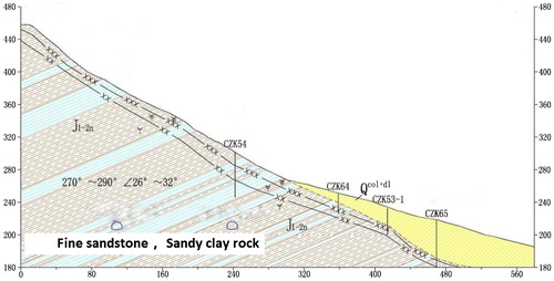
A landslide zone is developed along the reservoir side of the lateral reservoir of the mountain through the tunnel. The distance between the tunnel and the slide bed of landslide bedrock is about 80 m, and the nearest horizontal distance is about 160 m (as shown in ). It has a serious impact on the safety of the project.
Figure 1. The schematic diagram of the landslide at the tunnel.
2.2. Numerical model
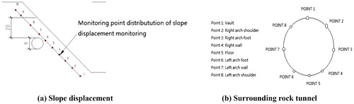
An ABAQUS tunnel excavation simulation model is established, which is simulated by the new Austrian tunneling method. Excavation of the specific methods and processes are embodied in the analysis step. See relevant wall rock parameters and the lining of the request based on the establishment of surrounding rock supporting structures and lining to simulate the tunnel excavation and construction. There are four main steps in the numerical simulation: loading the stress, stress release, supporting and removing the excavation unit, and then analyzing the changes of the displacement, stress and strain of the slope and surrounding rock in each step. Monitoring measurement point shown in .
Figure 2. Monitoring control point.
2.3. Surrounding rock and slope displacement analysis
Horizontal displacement of each stage cloud map
① Stress release
The method of changing surrounding rock parameters is used to simulate the dynamic excavation status of tunnels dynamically.
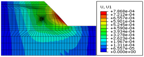
Analysis of stress release horizontal displacement of the cloud after the slope displacement, the slope from the foot to the slope, showing a large circular arc displacement. The displacement occurred about from 0.5901 to 0.7868 mm, upper part of the slope is more stable. For the surrounding rock, a displacement of about 0.200 mm appears around the entire tunnel. The surrounding rock on the left of the tunnel is relatively stable with the right side under the perturbation of excavation.
Figure 3. Horizontal displacement cloud after stress release (m).
② Activate the lining unit.
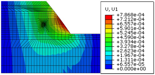
According to the actual construction steps, the corresponding support should be applied every time the completion of a full section excavation cycle footage. Activation of the lining components in the model is the process of applying lining in the construction. As can be seen from the displacement cloud in , after the lining is activated, the displacement of the slope tends to be stable. The area of the orange arc surface decreases, and the entire upper part of the slope is relatively stable. The displacement of each part of the slope ranges from 0.327 to 0.786 mm. The surrounding rock near the tunnel also stabilized.
Figure 4. Horizontal line after activation lining unit cloud (m).
③ Remove excavation unit
The excavation unit is removed, indicating the completion of a complete construction cycle footage. The displacement cloud is shown in . After activating the lining unit, the displacement of the whole tunnel and the slope has stabilized, and there is no further displacement. After activating the lining unit, the displacement near the entire tunnel and the slope have stabilized no more further displacement. The maximum displacement of the slope is reduced to 0.7712 mm. The plastic deformation zone on the left and right sides of the tunnel still shows a small amount of expansion, and the horizontal displacement of the side wall has also reached the maximum.
Figure 5. Horizontal displacement after removal of excavation cloud (m).
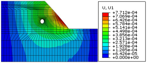
By analyzing the monitoring data of each horizontal displacement cloud and on the monitoring points of the slope displacement, the disturbance to the slope is the greatest when the tunnel has just been excavated. But the time of the disturbance is very short. When the lining is activated, the whole slope is gradually stabilized. It can also be seen from the various displacement images that the impact of tunnel excavation on the slope is also related to the position of the tunnel in the slope
Table 1. Slope control points of each displacement measurement/mm.
According to , after each construction cycle is completed, the horizontal displacement of the vault and floor has a smaller change, 0.005 and 0.004 mm respectively. This phenomenon may be in the process of geostress balance, the left side is the slope, the earth stress on the left side of the tunnel is greater than the right side, and the tunnel moves to the right.
Table 2. Surrounding rock tunnel control measurement point displacement/mm.
In the numerical simulation model, the horizontal displacement of the left shoulder of the tunnel is −0.226 mm, and the horizontal displacement of the right shoulder is 0.224 mm. The horizontal displacement of the left and right arch feet are −0.230 and 0.229 mm, respectively, and its horizontal displacement is at the displacement of the spandrel and side wall. It can be known that the lateral displacement near the side wall of the tunnel is greatly affected by the excavation of the tunnel. The side slope near the side wall will also have obvious displacement under the influence of the side wall of the tunnel. In the vertical displacement, the arch at the top of the vertical displacement of the largest value, the maximum value is −3.975 mm, and the left and right arch shoulders are comparatively slight, which are −1.180 and −1.001, respectively. There are also slight displacements at the left and right side walls of 0.001 and −0.002 mm, respectively; the displacement is 2.322 and 3.762 mm, respectively. While the maximum value of the bottom rebound is 2.781 mm. From the overall trend, the displacement of surrounding rock changes during tunnel excavation, and the displacements are different at different stages of excavation. During the initial stress release of the tunnel, the vertical displacement of the tunnel shows obvious changes, as the construction progresses, the amount of displacement change will be reduced, but as the tunnel is fully excavated, the tunneling displacement will accelerate rapidly. After each cycle footage excavation is completed, tunnel support is immediately carried out, which can effectively change the stress, strain, and displacement of the enclosure, and strengthen the stability of the surrounding rock and slope.
(2) Surrounding rock and slope stress analysis
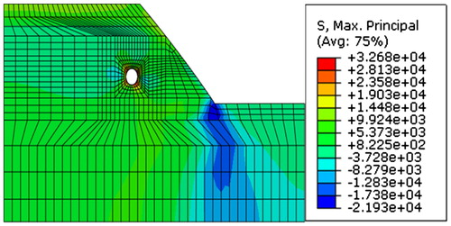
From to , it can be seen that the stress distribution of the entire simulated excavation process is under the condition of four types of simulation. After the stress is released, the entire stress distribution cloud is butterfly-shaped, and the negative stress, the maximum principal stress is mainly distributed in the tunnel vault and tunnel bottom. With the excavation of the tunnel, the rock slope appears loosening and the stress also appears negative. In , after the lining unit is activated, the stress value at the upper part of the slope becomes larger, and the stress value at the foot of the slope becomes smaller. The stress is mainly distributed around the side walls of the tunnel and the arc and inner arch on the vault. After activating the lining unit, the surrounding rock pressure decreases.
Figure 6. Maximum principal stress after stress release (Pa).
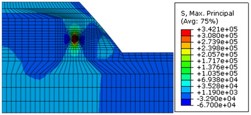
Figure 7. Maximum principal stress diagram after activation of lining unit (Pa).
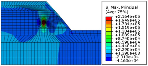
Figure 8. Maximum principal stress diagram after removing excavation unit (Pa).
3. Model test of tunnel excavation at lower side of slope
The experimental model is based on the actual engineering slope shape and engineering geology of a certain tunnel section of a high-speed railway tunnel. The comparison between the actually chosen tunnel slope and the model is as shown in . Under the condition of fully simulating the field environment, the test material can be reused many times, optimizing the monitoring scheme, controlling the cost and improving the cost performance of the model test. The contents of model test and monitoring are as follows: (1) the stress characteristics of the slope during tunnel excavation. (2) Tunnel excavation is the displacement caused by the slope.
Table 3. Actually selected test area and the model comparison.
3.1. Model similar materials
For the physical phenomenon reappeared on the model should be similar to the prototype, the model material, shape and load must follow the similarity principle of the geomechanical model test rules. It can be defined that the weight similarity ratio of the prototype and model is Cγ, the geometric similarity ratio is CL, the stress similarity ratio is Cσ, the strain similarity ratio is Cε, the displacement similarity ratio is Cδ, and the elastic modulus similar ratio CE, the similarity ratio for Poisson's ratio is Cμ, the cohesion ratio is Cc, the internal friction ratio is Cφ. All the similarity ratio follows the similar criteria:
(1)
(1)
Material composition
Based on the typical tunnel underpass slope project in the high-speed railway tunnel project, this experiment selects one section of the tunnel under passing slope project as the simulation object of the model test.
The similar material used in the model test is made of medium-fine sand, gypsum powder and rosin alcohol solution in which taking medium fine sand as aggregate, gypsum powder as gap sealant, rosin alcohol solution as binder (shown in ). All the above raw materials were uniformly mixed and compacted according to the specified ratio. This kind of similar material has the advantages of a high bulk density, a wide range of mechanical parameters, stable performance, low price, fast drying, simple and non-toxic harmless, which could be used to simulate most of the rock material from soft to hard.
In order to understand the performance of various raw materials under different conditions of different proportions, a plurality of test specimens were prepared, each with 2 to 3 specimens. Stir well with a mixer and mix well into a mold (similar material specimen Making and testing were shown in ), compaction, and then release label and place at room temperature for drying.
Mechanical parameters
In order to study whether the materials used can well show the characteristics of rock strata in practical engineering, a great deal of tests were carried out to study the variation rules of physical parameters and mechanical characteristic parameters of the raw materials in the process of compounding. The variation of compressive strength, elastic modulus of similar material with the components was shown in . It can be obtained from the graph that the higher the fine sand content is, the higher the strength and elastic modulus of the sample are. However, when the volume ratio of fine sand to barite powder is greater than 0.3, the maximum value of this type of formulation is basically obtained. For the increase of fine and fine sand aggregate content increases the density of the sample, the compressive strength and elastic modulus of the sample will increase.
Prototype parameters were measured by indoor rock triaxial tests of field sampling (shown in ). By adjusting the proportions of the compositional components of the similar material, the matching ratio for the slope-tunnel model material can be obtained (shown in ).
Figure 9. The main components of similar materials.
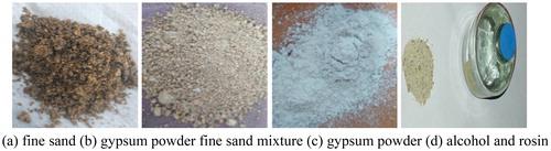
Figure 10. Similar material specimen making and testing.
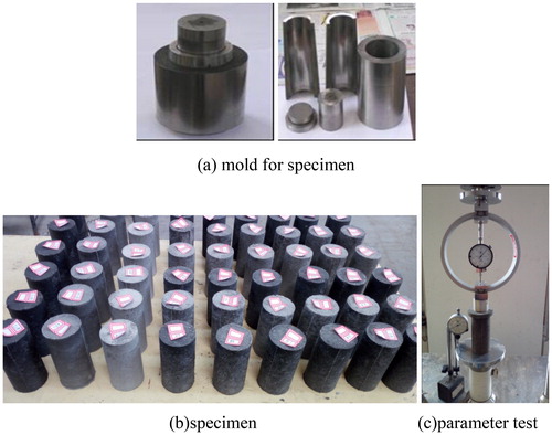
Figure 11. Similar material composition of the mechanical parameters of the curve.
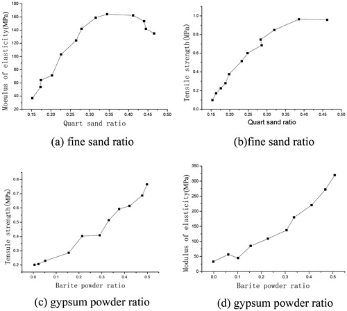
Table 4. Stratum physical and mechanical parameters.
Table 5. Mechanical parameters of prototype and model similar material.
3.2. Monitoring system
Multi-point displacement meter test system
The multipoint displacement meter test system consists of measuring points, bushing, wire rope, positioning frame, grating ruler (Vernier caliper) and so on. The main advantages of this system are high sensitivity and good stability. But its shortcoming is very easy to damage, so the requirement for test is high. It is mainly used for embedded and real-time displacement display, displacement measuring point as shown in .
Figure 12. Grating ruler multi-point displacement measurement points.
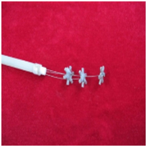
Grating ruler multi-point displacement meter consists of: grating ruler, rigid fixed point, flexible steel wire, conduit and tube support frame, so on. After the converter converts the electrical signal into a digital signal and transmits it to the computer, the data processing is completed by the data acquisition program.
DH3818 static strain test data acquisition system
DH3818 static strain test data acquisition system to support the connection with the computer, enabling rapid stress and strain measurements. The system has a built-in resistance, and has the function of automatic balance. It is easy to realize full bridge and half bridge connection. It has extensive application in the soil mechanics model test. In the test process, combined with the computer control software, you can achieve the entire data collection, management of documents, setting parameters, balance operations, sampling control and other functions. Monitoring steps to open the already installed software, the software will automatically find the chassis has been connected, then the parameters are set, set the parameters to be tested. Balance the instrument, set the sampling method. After the test is completed, the sampling operation of the measuring point is carried out. Finally, the data collected will be summarized and processed.
3.3. Slope model production
To determine the model body size
Based on the typical tunnel underpass slope project in a high-speed railway tunnel project, this experiment selects a section of the tunnel under the slope project as a model test simulation object. With medium fine sand as aggregate, alcohol rosin solution and gypsum powder as cementing agent, a slope model is made according to a certain proportion. Fine sand as aggregate, with alcohol rosin solution and gypsum powder as binder mixed through the model test using gypsum powder, fine sand according to a certain proportion of the slope model. The unit is cm. The basic edge parameters as shown below. The height of the tunnel slope is changed to 0.5 m and the slope foot is 45°. The axial direction of the tunnel to be excavated is perpendicular to the sliding direction of the slope. The maximum span of the tunnel is 9 cm. The vertical distance from the roof to the slope is 0.2 m.
(2) Components buried
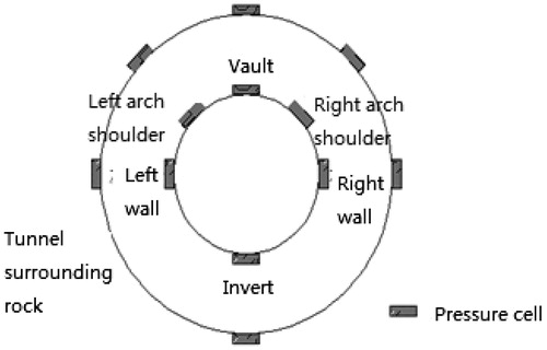
In this model test, the pressure box is arranged by selecting the middle section of the model tunnel as the cross section.
Since this model test also monitors the stability of the slope during excavation of the tunnel, five pressure boxes are arranged on the upper part of the tunnel and five pressure boxes are arranged diagonally on the right shoulder. The left side of the wall outward layout of 5, the tunnel placed four, the right side of the wall layout of two, a total of 21 pressure box layout (). A data collection for every excavation of 3 cm.
Figure 13. Model tunnel around the pressure box location layout.
The grating multi-point displacement meter is used to monitor the displacement of the slope surface during excavation. The displacement measuring point is embedded near the slope.
3.4. Tunnel excavation simulation test model as a step
The production of models is a crucial part of model testing. The accuracy of data acquisition depends largely on it. The experimental model using layered compaction fill production method, the basic production process as shown in the following steps:
Purchase the material needed for the test.
Accurate proportioning of gypsum powder, medium fine sand and other raw materials can be made by a certain proportion.
Mix the materials well with a blender and stir with water.
The evenly stirred material was transported to the test bench and the material was layered and filled from the bottom to the top. Every layer should be compacted before filling the next layer.
According to the test plan, the pressure box is buried in selected sections in different layers, and multi-point displacement meters and grating sensors are buried. In the process of embedding the pressure box, pay attention to leveling the model material of the contact surface of the pressure box first.
In the process of model filling, special attention should be paid to the control of the model density, that is, the number of times the rubber hammer is hit during compaction. When the density of the model is proportional to the density of the actual project, the accuracy of the test can be guaranteed.
3.5. Slope excavation simulation model excavation process
The simulation test is to study the stress–strain displacement simulation analysis of the excavation of full-face excavation tunnel and slope stability. During excavation, no support is needed, and the length of the model tunnel to be excavated is 100 cm. According to the actual working condition of the tunnel, full face excavation method was used and the cycle of excavation footage was 3 cm shows the stress release data collection.
Table 6. Radial load release rate (%).
3.6. Results analysis
3.6.1. Analysis of stress release results
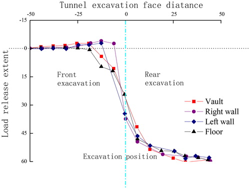
In the experiment, the pressure box was placed in the monitoring section to monitor the pressure change of the tunnel and slope. When the tunnel is excavated, the pressure value of the pressure box at each monitoring point begins to change due to the closer distance between the monitoring surfacing and the free surface. In order to conduct a comprehensive study of the monitored data and stress release process, the data obtained from monitoring were normalized. The monitored end faces are located in the middle of the model and are excavated on both sides for data collection. When the monitoring surface is not excavated, the distance between the tunnel face and the monitoring surface is negative. When excavated, the distance is positive. is the degree of stress release during the full face tunnel excavation. Through the analysis of the data in the figure, it can be seen that the stress release of the tunnel surrounding rock during the excavation is mainly influenced by the surrounding rock disturbance of the tunnel excavation, and the stress changes are more obvious. After crossing the monitoring section, the degree of stress release is accelerated due to the free surface of the tunnel.
Figure 14. Stress release of tunnel wall.
3.6.2. Slope displacement results analysis
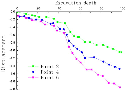
The data of slope displacement were recorded in every 10 cm of tunnel excavation. After processing, the displacement curve is drawn by even number of measuring points, as shown in . Analysis of grating displacement system monitoring data obtained, the slope of the total surface displacement is increasing, and the maximum displacement reached 1.28 mm. When the tunnel face is excavated to 50 cm distance, the displacement velocity of the slope suddenly increases, which is caused by the continuous excavation of the tunnel and the increasing of the free surface. Compared the final displacement of the slope in the model test with the numerical simulation, it is showed that the result of the final displacement of the slope surface in the model test is in good agreement with the numerical results.
Figure 15. Slope displacement curve.
4. Conclusion
In the simulation, the stability of slope and tunnel surrounding rock were mostly affected in two stages–in the beginning of excavation and after the excavation is completed. After the lining unit was activated, the slope and the surrounding rock were rapidly stabilized. Therefore, the in-time lining after excavation could enhance the whole stability of the slope and tunnel.
Combined with indoor model test and ABAQUS numerical simulation, the disturbance of tunnel excavation to the surrounding rock and slope is the largest. Longitudinal displacement of surrounding rock and slope near the tunnel are obvious, while the maximum principal stress is proportional to the depth of the soil, under the influence of slope bias, the tunnel lining pressure closed to the slope surface was lower.
Tunnel excavation tends to cause disturbance to the displacement field of slope, and the monitoring data of slope displacement caused by tunnel excavation are in good agreement with the numerical analysis. The impact area of tunnel excavation under the slope range from 1.5 times the tunnel span. Therefore, the surface of the slope and the tunnel support should be well strengthened and monitored. Based on the construction of the surrounding rock-slope interaction system of the tunnel, aiming at the geological conditions of the landslide in the slope where the tunnel was located, it is suggested to stabilize the slope first before tunnel construction. The conclusion could provide reference for the overall stability of tunnels and slopes in mountain tunnel construction.
Acknowledgement
Great appreciation goes to the editorial board and the reviewers of this article. This work was supported by the National Natural Science Foundation of China (Grant No. 51609138, 51909157, 41472294), China Postdoctoral Science Foundation ( Grant No. 2018M630780, 2018M641671 ), Natural Science Foundation of Hebei Province (Grant No. E2017210147), Collaborative Innovation Center for Disaster Prevention & Mitigation of large basic infrastructure in Hebei Province.
Additional information
Funding
References
- Gao WX, Zhuo ZC, Hou BH, Chen N. 2010. Road high cutting slope stability analysis under the influence of blasting for excavation. Chin J Rock Mech Eng. 250–253:3163–3167.
- Golestanifar M, Goshtasbi K, Jafarian M, Adnani S. 2011. A multi-dimensional approach to the assessment of tunnel excavation methods. Int J Rock Mech Mining Sci. 48(7):1077–1085.
- Gupta V, Bhasin RK, Kaynia AM, Kumar V, Saini AS, Tandon RS, Pabst T. 2016. Finite element analysis of failed slope by shear strength reduction technique: a case study for Surabhi Resort Landslide, Mussoorie township, Garhwal Himalaya. Geomat Nat Hazards Risk. 7(5):1–14.
- Jia DY. 2017. Numerical analysis for effect of tunnel excavation by blasting on slope stability of portal section. Mining Metall Eng. 37(1):25-28.
- Kaya A, Akgün A, Karaman K, Bulut F. 2016. Understanding the mechanism of slope failure on a nearby highway tunnel route by different slope stability analysis methods: a case from NE Turkey. Bull Eng Geol Environ. 75(3):945–958.
- Li H. 2014. Stability analysis of slope in tunnel portal. Munic Eng Technol. 32(01):103–105.
- Liu Z. 2014. Study on the influence of tunnel excavation position on slope stability. J Geotech Eng. 28(05):79–82.
- Ma K, Tang CA, Liang ZZ, Zhuang DY, Zhang QB. 2017. Stability analysis and reinforcement evaluation of high-steep rock slope by micro seismic monitoring. Eng Geol. 218: 22–28.
- Ma HM, Wu HG. 2011. Practice of prevention and treatment of diseases of high slope in mountainous expressway. J Railw Eng Soc. 154(7):34–41.
- Matsui T, San K-C. 1992. Finite element slope stability analysis by shear strength reduction technique. Soils Found. 32(1):59–70.
- Vlachopoulos N, Vazaios I, Madjdabadi B. 2018. Investigation into the influence of excavation of twin bored tunnels within weak rock masses adjacent to slopes. Can Geotech J. 55: 1533–1551.
- Wang M, Liu K, Yang G, Xie J. 2017. Three-dimensional slope stability analysis using laser scanning and numerical simulation. Geomat Nat Hazards Risk. 8: 997–1011.
- Wang JX, Tang YQ, Zhou Nianqing ZH, Wang Hongxia LY. 2006. Three-dimensional monitoring analysis of slope deformation in multi-arch tunnel. Chin J Rock Mech Eng. 11:2226–2232.
- Wang J, Zeng Y, Xu Y, Feng K. 2017. Analysis of the influence of tunnel portal section construction on slope stability. Geol Ecol Landsc 1(1):56–65.
- Zhang Q, Wang JC, Zhang HX. 2017. Attribute recognition model and its application of risk assessment for slope stability at tunnel portal. J Vibroeng. 19(4):2726–2738.
- Zhu Z. 2007. Slope and tunnel interaction analysis and mathematical quadratic programming application. Tongji University.
- Zienkiewicz OC, Humpheson C, Lewis RW. 1975. Associated and non-associated visco-plasticity and plasticity in soil mechanics. Geo. Tech. 25(4):671–689.