
 ?Mathematical formulae have been encoded as MathML and are displayed in this HTML version using MathJax in order to improve their display. Uncheck the box to turn MathJax off. This feature requires Javascript. Click on a formula to zoom.
Abstract
Stability of the slopes along the rock cut on hilly roads are a major concern because slope failures lead to disruption of traffic and loss of property/life. The Markundi hill near Chopan, District Sonbhadra is characterized by moderate strength and highly jointed rock with rugged topographic features has experienced several episodes of rockfall activities. This geological phenomenon disturbs the traffic on SH-5 which is lifeline to eastern U.P., parts of M.P., Bihar and Jharkhand States of India. An attempt has been made to assess the present geotechnical condition of the rock mass and demarcate the nature and locations of possible failure using rock mass characterization techniques and kinematic analysis. On the basis of RMR values, section-1 and section-2 having poor to fair quality rock mass while on the basis of SMR investigation, section-1 and section-2 falls in partially stable to unstable class, respectively. Kinematic analysis suggests that slopes are unstable and wedge failures are commonly observed along both left and right slope sections.
1. Introduction
Disaster caused by any natural hazards such as floods, landslides, cloudburst are common and the risk can be accepted. Rockfall and rockslides are very common among landslides and are mostly caused by inadequate geological investigations or improper design selection (Singh et al. Citation2013; Kainthola et al. Citation2015). Transportation corridors are often susceptible to rockfall hazards and in particular, mountainous regions experiences rockfall almost on a daily basis. The unpredictability associated with the frequency and magnitude of a rockfall event potentially endangers people and infrastructure (Dorren Citation2003). Therefore, it is very important to assess the geological and geotechnical details of the cut slopes and demarcate the probable failure zones in order to prevent/reduce the potential damage.
Rockfall refers to the movement of loose blocks along the slopes under the influence of gravity (Keskin Citation2013; Singh et al. Citation2013). The movement of blocks can be through free fall, roll, slide, bounce or a combination of these and the entire activity is controlled by the surface profile of the slope face and the rock material involved. On a vertical slope, movement of loose blocks is mainly by free fall but with gradual decrease in slope angle, the movement of the blocks transforms to roll, bounce and slide. However, sliding of a block is generally observed in the initial and final stages of a typical rockfall event and if the slope gradient does not change, the sliding block will lose all its kinetic energy due to friction and finally stop (Bozzolo and Pamini Citation1986; Dorren Citation2003).
Markundi hills are a common attraction point in an otherwise flat plains of Uttar Pradesh, India. Road widening activities have exposed a continuous stretch of several miles of highly jointed rock mass along the treacherous roads. In addition to this, the blocks have become loose along the joint planes due to blasting and mechanical excavation and a number of block failure have been observed now and then. However, in majority of the cases, a large slope failure has not been observed rather block (of varying size) detachment from the slope face is more common.
Among various available rock mass classification techniques, rock mass rating (RMR) is undoubtedly a helpful tool for rock mass characterization, planning and design in engineering applications, but with due consideration of the limits and applicability in each geological setting in relation to different engineering geological problems. RMR technique is based on detailed field and laboratory study which involves collection of data at site slopes, strength of rock exposed on slope face, spacing of discontinuities, orientation of discontinuities, and ground water condition. Despite several benefits of RMR, the technique itself does not provide much information about the failure mode and direction off movement. In addition, rock quality designation, a parameter used in RMR, gives poor results for highly jointed and weak rock mass. Slope mass rating (SMR) developed using basic RMR is a much better tool to study slopes and have been applied worldwide to understand the stability and probability of failure for natural and engineered slopes (Romana Citation1985; Romana et al. Citation2003; Umrao et al. Citation2011). The SMR method for slope stability analysis has all the basic parameters of RMR as well as it also includes some adjustment factors of the slope-joint interaction and the impact of method of excavation (Sujatha and Thirukumaran Citation2018). In the present study, RQD has been calculated using Volumetric joint of rock mass (Palmstrom Citation1974).
A block detachment can take place by any of the failure modes such as plane, wedge and topple. It has been noted that most rockfall activities are a result of plane and wedge type of failure (Mavrouli et al. Citation2009; Singh et al. Citation2016). Plane and wedges are formed on a variety of scales and therefore the block size, volume and intensity can vary significantly. The kinematic stability of blocks can be studied by kinematic analysis, a very useful method to determine the possible failure mode in jointed rock masses and has been used by several researchers (Markland Citation1972; Lucas Citation1980; Hudson and Harrison Citation2000; Yoon et al. Citation2002; Lisle and Leyshon Citation2004).
The idea of this article is to characterize the rock mass and employ various available tools and techniques to identify the loose blocks, the type of movement and finally demarcate the probable failure zones.
2. Study area
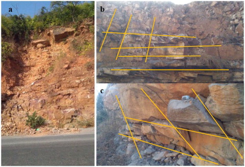
The area under investigation is a part of Markundi Hill lying in between longitudes of 83°2'30"–83°3′04" E and latitudes of 24°37'05"–24°37'30" N under Survey of India toposheet no. 63 P/2. The major eleven locations (S-1-1, S- 1-2, S-1-3, S-1-4, S-2-1, S-2-2, S-2-3, S-2-4, S-2-5, S-2-6 and S-2-7) under two sections were chosen for the study area. The rocks in general belong to Kaimur group of Upper Vindhyan super group and can be classified under Dhandraul Quartzite and Scarp Sandstone formations. Topographically, the area is characterized by rugged and undulating hills which have been cut haphazardly leading to the increased incidence of block failures intermittently. The cut slopes are on the top of Markundi fault which separates Kaimur sandstone from the Bijawars basement. The signatures of deformation can be very well observed along the cut slope in the form of variation in block size. There is a minor shear zone of approximately 4–6 m in width where the jointing is intricate resulting in significant decrease in block size (). In the entire stretch, the block size is highly variable leading to sporadic rockfall activities (). The persistence of rock joints is significantly less, even the bedding parallel joints have lost their continuity either due mechanical excavation and blasting process or probably due to its occurrence in fault terrane. Due to blasting and mechanical excavation, rock joints have opened significantly which can be observed in the form of increased joint apertures (). The low persistence, intricate joint pattern and variable block size has caused regular block failures along the entire stretch. The cut slope face has a very steep gradient which removes the possibility of slide related failure, even most wedges that are formed are detached not by sliding along the line of intersection but by free fall under the gravity. The average annual rainfall is 1100 mm during monsoon period. Rockfall, in the form of block detachment of variable size, has been observed for the past two years mainly during the months of August to November and this has been verified during regular field visits post monsoon (http://hydro.imd.gov.in/hydrometweb/(S(xvrclguzjqtozl55wu4yls45))/DistrictRaifall.aspx).
Figure 1. Slope sections of Markundi area showing (a) minor shear zone, (b) variable block size, and (c) opening of joint aperture due to uncontrolled blasting.
3. Methodology
The purpose of this study is to identify the probable failure zones along the investigated stretch which is done by following three-fold steps. First step involves rock mass characterization according to rock mass rating technique. This step is followed by analyzing the joint data (persistence, spacing, aperture, infilling, orientation) simultaneously in order to identify the loose blocks and later to assess the type of movement by which blocks fail. Third step is the application of RMR and failure mode of blocks in establishing SMR values for the investigated zones. These techniques require rigorous field investigations to record various parameters like rock quality designation (RQD), weathering conditions, groundwater conditions, the attitude of rock beds and joint parameters along with slope face direction apart from sample collection. Therefore, field investigation was carried out along SH-5 and eleven locations were selected for further detailed analysis. The selection of locations was primarily on the basis of RQD and weathering conditions. The methods for each step are discussed below.
3.1. Rock mass rating (RMR)
Bieniawski (Citation1976) published the details of a rock mass classification called the Geomechanics Classification or the Rock Mass Rating (RMR) system. Although, the modified RMR (Bieniawski Citation1979) is used in the study to classify the rock mass which uses only first five parameters viz. strength of intact rock, RQD, spacing of discontinuities, condition of discontinuities and groundwater conditions (Roghanchi et al. Citation2013). The equivalent I.S. code for obtaining the value of RMR is IS:13365 part 3 (1997) (IS: 13365 Citation1997). While most parameters can be determined in the field itself, strength is determined in laboratory. Therefore, laboratory experiments were conducted to determine the strength of the samples by unconfined compression test as per IS: 9143-Citation1979 (IS: 9143 Citation1979). RQD has been estimated from joint spacing or volumetric joint count. The approximate relationship between RQD and joint volume (Jv) (ISRM Citation1978) is given by following equation;
(1)
(1)
where Jv is defined as the number of joints intersecting a volume of 1 m³, where the jointing occurs mainly as joint sets. The volumetric joint (Jv) count was introduced by Palmstrom (Citation1974)
(2)
(2)
where S1, S2, and S3 are the average spacing for the joint sets.
3.2. Slope mass rating
Slope mass rating (SMR) is a modification of Bieniawiski’s rock mass rating and is particularly designed for assessing the stability of slopes. The advantage of this method is that it incorporates the orientation of joints with respect to slope face and is able to delineate the possibility of failure. So, it is an important approach to assess the engineering behavior of a rock slope. Romana (Citation1993) introduced SMR system to cater for the limitation of the RMR by adding some adjustment factors (F1, F2, F3 and F4) in RMRB. SMR can finally be calculated using EquationEquation (3)(3)
(3) (Romana Citation1985, Citation1993; Romana et al. Citation2003).
(3)
(3)
where RMRBis the basic RMR index resulting from rock mass classification of Bieniawski without any correction; F1 is the parallelism between discontinuity dip direction and slope dip; F2 is the discontinuity dip; F3 is the relationship between slope and discontinuity and F4 is the correction factor that depends on the excavation method used.
The effectiveness of SMR has been shown by several researchers around the world in different geological conditions and the value has been used to design and increase the engineering life of the slope (Romana Citation1985, Citation1993; Palmstrom Citation1974; Umrao et al. Citation2011; Roghanchi et al. Citation2013).
3.3. Kinematic analysis
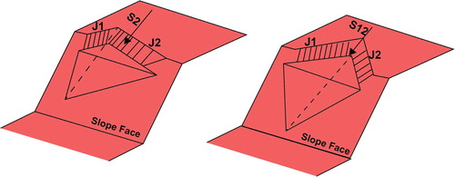
The identification of different mode of slope failure is an important criterion to analyze the stability of slopes for rock mass characterization. Kinematic analysis is a process to identify the probable failure mode which depends on structural relationship between the orientation of discontinuities and slope face (Wyllie and Mah Citation2005). The analysis is a purely geometric technique allowing to visualize the possible mode of failure in a jointed rock mass. Slope failure can take place by plane failure or more commonly by wedge failure. Markland (Citation1972) proposed that the wedges are formed by the intersection of the two joint planes and these intersection lines must through the light on the slope face and at the same time the plunge of intersection must be also greater than the friction angle of the joint planes (Markland Citation1972). Hocking (Citation1976) and Cruden (1978) later modified wedge failure on the basis of sliding plane of wedges (Hocking Citation1976; Cruden Citation1978; Yoon et al. Citation2002]. A single plane sliding (plane failure) would result from sliding on a single joint plane whereas double plane sliding would result from sliding along the intersection of two planes similar to wedge failure (). An important criterion was later proposed by Hoek and Bray (Citation1981) that the strike of sliding plane must be in the range of ±20° to the slope face for single plane sliding and becomes meaningless for wedge failure as the sliding direction is defined by the intersecting line between the two planes (Hoek and Bray Citation1981). Failure envelope is uniquely defined by friction angle and slope face which for both the cases are different and helps to identify all those planes that might lead to plane or wedge failure.
Figure 2. Structural relation of joints (J1 and J2) with slope face leading to single and double plane sliding. S2 and S12 denotes sliding along only J2 joint and along the line of intersection of J1 and J2, respectively (modified after Yoon et al. (Citation2002)).
4. Results and discussion
The results of this rigorous study have helped to highlight some common problems along the entire stretch and this has been presented in terms of rock mass characterization and kinematic analysis. Field investigation along the cut slopes in the study area has highlighted the present geotechnical condition of the exposed rock mass. The outcrops are mainly of sandstone and quartzite which have near horizontal bedding along with several joint sets. The structural disposition of joints in relation to slope face are such that they form a series of wedges of varying size leading to sporadic block failure.
Among several rock joint parameter, joint persistence is important while assessing the problems of detachment and subsequent movement of blocks (Einstein et al. Citation1983; Mahanta et al. Citation2016). In engineered slopes, excavation and blasting processes continuously disturb the rock masses and exposes the fully persistent discontinuities enabling kinematic release of blocks (). However, natural slopes do not experience such rapid changes in kinematic state of blocks and therefore, the slope is stable for considerably longer periods of time (Eberhardt et al. Citation2001). In massive rocks, joints may be fully persistent or they may be connected through rock bridges which are intact rocks. For a slope to fail in a material where rock joints are connected through intact rock bridges, progressive degradation along with destruction of rock bridges would be required. Progressive failure in massive rock would mean that shear strength of intact rocks has been exceeded which is significantly higher than rock joint shear strength (Eberhardt et al. Citation2004). Weathering along the bedding joints are very prominent which can be observed in S-1-2, S-2-4 and S-2-7 and at several places, degradation of entire rock mass to soil can be observed as can be observed in S-1-1 ().
Rock mass characterization was done by employing RMR technique. The rating values of each parameter for the studied slope sections are given in and which shows significant variation for even a very small stretch. Ratings were given according to the average values of mean discontinuity spacing (mm), roughness, separation, continuity and groundwater condition of joints. RQD values were obtained by field survey using volumetric joint count. This parameter itself is able to demonstrate the present condition of rock mass. Wide variation in RQD is an indication of varying block size and is also responsible for irregular RMR values along the entire stretch.
Table 1. RMRB rating values of rock mass along the SH-5 and rock mass class of section-1.
Table 2. RMRB rating values of rock mass along the SH-5 and rock mass class of section-2.
RMR shows the present geotechnical condition of the rock mass but sheds almost no light on the stability of slopes. Slope mass rating based on RMR provides more useful information in terms of stability of slopes by taking orientation of joint into consideration. On the basis of RMR values and field observations, the following data has been collected to assess SMR ( and ).
Table 3. Calculation of slope mass rating (SMR) and description of stability classes of Section-1.
Table 4. Calculation of slope mass rating (SMR) and description of stability classes of Section-2.
SMR values for all the sections fall under partially stable or unstable condition suggesting failure of blocks at all the studied locations. This highlights the immediate need to strengthen the cut slopes as the roadways is very busy throughout the year owing to its scenic view and connecting link to other states. An added problem is introduced in the form of opening of joint apertures and creation of loose blocks due to improper blasting (). The surficial joints have opened up leading to almost negligible shear resistance offered by them allowing the blocks to detach from the slope face very easily. A slight trigger due to vibration or rainfall can lead to detachment of such blocks and can cause series of rockfall activity along the entire stretch. This has also been confirmed during the field visits as several blocks were found on the sides of the roadways mostly on the left slope section.
Among all the techniques, kinematic analysis provides reliable information related to movement direction of the wedges or blocks. Kinematic analysis has been performed in section-1 and section-2 using stereographic projection in the study area. The equal area method under stereographic projection has been applied.
The right slope in section-1 has slope facing towards NW direction similar to bedding planes but dipping at much steeper angle than bedding. The bedding has gentle dip of 10–15°. The other two joint planes are common but are difficult to identify sometimes mainly because of uncontrolled blasting.
The intersection of the two joints (W1) falls in the failure envelop (pink zone) in marked by slope face and friction angle which is directed towards northerly direction. Similar case is observed along left slope in section-2 where joint intersection (W1) falls in the failure envelop and failure direction is southerly in . Three joint patterns form number of wedges of different sizes and sliding surface formed by the joints is also be observed ().
Figure 3. (a and b) Stereographic projection of Section-1 and Section-2 slope sections under investigation at Markundi, Sonbhadra (U.P.).
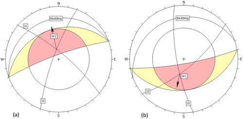
Figure 4. Complex joint pattern observed along cut slopes at Markundi Hill, Sonbhadra (U. P.). The bedding parallel joint along with two other joints forms wedge of varying sizes leading to rock fall along the entire cut slope.
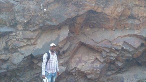
While the failure pattern is mostly structurally controlled, a number of failures can also be observed due to intense weathering along bedding planes (). The rock mass has graded to soil type material at several places and in such zones, failure is governed by mixed mode or possibly circular failure at a later stage. The opening of joint apertures has further increased the intensity of weathering by allowing free flow of water to deeper level in the slopes.
5. Preventive measures
Uncontrolled blasting has exposed several loose blocks of variable size along the entire stretch. The first step would be to either stitch the unstable blocks wherever possible through bolting otherwise larger unstable blocks may also be removed from the slopes to prevent future failures. Systematic rock bolts may be applied throughout the studied section to stabilize the entire mass. Application of steel wire mesh is advisable in order to withstand the accumulated force of falling blocks and to prevent the blocks to fall on roadways. Since the environment in the study area is aggressive, protection of wire mesh for long term corrosion is feasible. The wire mesh should also be installed few meters above the crest of the slope face so that the mesh does not fail entirely due to block failures from the crest of the slope. A 50 mm thick layer of shotcrete is also suggested before the installation of wire mesh. This will seal the cracks and provide a cover on the exposed surface and at the same time it will also help to decrease the rebound characteristics of the slope surface.
6. Conclusion
The present study area has not been attempted for such study till date; however, it is quite susceptible for rock fall. The present study/research reveals about the character of entire rock mass in the form of RMR and SMR while kinematic analysis has been performed using dip and strike of rock beds and their discontinuities. Synthesis of these analyses conclude that the wedge failure is common in section-1 following NNW and section-2 SSW direction.
The study was conducted to identify the vulnerability of rock cut slopes for their stability at eleven most vulnerable locations of two sections (section-1and section-2). RMRB, SMR, and kinematic analysis were determined for both sections. UCS of intact rock mass ranges from 6.25 MPa to 26.53 MPa and 13.25 MPa to 37.18 MPa for section-1 and section-2, respectively indicating that the rock is very weak and weak strength. RMRB is an essential parameter for determination of SMR. RMR value ranges from 30 to 45 and 35 to 58 for section-1 and section-2, respectively which indicate that this rock mass lies under poor to fair quality. SMR value varies from 30 to 45 and 35 to 58 for section -1 and section-2, respectively indicating that rock mass is in unstable and partially stable. Kinematic analysis of both sections corroborates about the wedge failure. Therefore, the rock mass along the SH-5 at Markundi Hill particularly in section-1 and section-2 in study area, District Sonbhadra, U.P. falls under unstable and partially stable condition, respectively. These findings indicate about the immediate attention for preventive measures.
Disclosure statement
No potential conflict of interest was reported by the author(s).
Related Research Data
References
- Anbalagan R, Singh B, Chakraborthy D, Kohli A. 2007. A field manual for landslide investigations. A Publication of Department of Science and Technology Government of India; p. 1–153.
- Basahel H, Mitri H. 2017. Application of rock mass classification systems to rock slope stability assessment: A case study. J Rock Mech Geotech Eng. 9(6):993–1009.
- Bieniawski ZT. 1976. Rock mass classification in rock engineering. In: Bieniawski ZT, editor. Exploration for rock engineering, proceedings of the symposium. Cape Town: Balkema; p. 97–106.
- Bieniawski ZT. 1979. The geomechanics classification in rock engineering applications. In: Proceedings of the 4th Congress of the International Society of Rock Mechanics, Montreux, Switzerland. Rotterdam: AA. Balkema; Vol. 2, p. 41–80.
- Bozzolo D, Pamini R. 1986. Simulation of rock falls down a valley side. Acta Mech. 63(1–4):113–130.
- Cruden DM. 1978. A method of distinguishing between single and double plane sliding of tetrahedral wedges. Int J Rock Mech Mining Sci Geomech Abstr. 15(4):217–217.
- Dorren L. 2003. A review of rockfall mechanics and modelling approaches. Prog Phys Geogr. 27(1):69–87.
- Eberhardt E, Stead D, Coggan JS. 2004. Numerical analysis of initiation and progressive failure in natural rock slopes—the 1991 Randa rockslide. Int J Rock Mech Min Sci. 41:69–87.
- Eberhardt E, Willenberg H, Loew S, Maurer H. 2001. Active rockslides in Switzerland—understanding mechanisms and processes. In: International Conference on Landslides—Causes, Impacts and Countermeasures, Davos; p. 25–34.
- Einstein HH, Veneziano D, Baecher GB, O'Reilly KJ. 1983. The effect of discontinuity persistence on rock slope stability. Int J Rock Mech Min Sci Geomech Abstr. 20(5):227–236.
- Hocking G. 1976. A method for distinguishing between single and double plane sliding of tetrahedral wedges. Int J Rock Mech Min Sci Geomech Abstr. 13(7):225–226. v
- Hoek E, Bray JW. 1981. Rock slope engineering. London: Institution of Mining and Metallurgy.
- Hudson JA, Brown ET, Fairhurst C, Hoek E. 1993. Comprehensive rock engineering: Principles, practice, and projects. London: Imperial College of Science, Technology & Medicine; p. 1–45.
- Hudson JA, Harrison JP. 2000. Engineering rock mechanics – an Introduction to the principles. Oxford, UK: Pergamon Press.
- IS: 13365. 1997. Quantitative classification system of rock mass-guidelines. Part-3: Determination of slope mass rating. New Delhi: Bureau of India Standards.
- IS: 9143. 1979. Method for determination of unconfined compressive strength of rock materials (BIS). New Delhi: Bureau of India Standards.
- ISRM. 1978. Suggested methods for quantitative description of discontinuities of rock mass. Int J Rock Mech Min Sci. 15:319–368.
- Kainthola A, Singh PK, Singh TN. 2015. Stability investigation of road cut slope in basaltic rockmass. Mahabaleshwar, India. Geosci Front. 6(6):837–845.
- Keskin I. 2013. Evaluation of rock falls in an urban area: the case of Boðaziçi (Erzincan/Turkey). Environ Earth Sci. 70(4):1619–1628.
- Lisle JR, Leyshon PR. 2004. Stereographic projection techniques for geologists and civil engineers. Cambridge, UK: Cambridge University Press.
- Lucas JM. 1980. A general stereographic method for determining the possible modes of failure of tetrahedral rock wedge. Int J Rock Mech Min Sci Geomech Abstr. 17(1):57–61.
- Mahanta B, Singh HO, Singh PK, Kainthola A, Singh TN. 2016. Stability analysis of potential failure zones along NH-305, India. Nat Hazards 83(3):1341–1357.
- Markland JT. 1972. A useful technique for estimating the stability of rock slopes when the rigid wedge slide type of failure is excepted. Ann Arbor, MI: University Microfilms.
- Mavrouli O, Corominas J, Wartman J. 2009. Methodology to evaluate rock slope stability under seismic conditions at Sola de Santa Coloma, Andorra. Nat Hazards Earth Syst Sci. 9(6):1763–1773.
- Palmstrom A. 1974. Characterization of jointing density and the quality of rock masses (in Norwegian). Internal Report. A.B. Berdal, Norway; p. 26.
- Roghanchi P, Kallu R, Thareja R. 2013. A new expression of three adjustment factors of slope mass rating (SMR) classification. Int J Earth Sci Eng. 6, 7–17.
- Romana M, Serón JB, Montalar E. 2003. SMR geomechanics classification: application, experience and validation. In: Merwe JN, editor. Proceedings of the 10th Congress of the International Society for Rock Mechanics, ISRM 2003—Technology Roadmap for Rock Mechanics. South African Institute of Mining and Metallurgy; p. 1–4.
- Romana M. 1985. New adjustment ratings for application of Bieniawski classification of slopes. In: Proceedings of the International Symposium on Role of Rock Mechanics, Zacatecas, Mexico; p. 49–53.
- Romana M. 1993. SMR classification: Romana M, Proceeding of the 7th ISRM International Congress on Rock Mechanics, Aachen, 16–20 September 1991, V2, P955-960. Rotterdam: A. A. Balkema; 1991. Int J Rock Mech Mining Sci Geomech Abstr. 30: A231–A231.
- Singh B, Goel RK. 2011. Engineering rock mass classification. Amsterdam: Elsevier, Inc. Publication; p. 364.
- Singh PK, Kainthola A, Panthee S, Singh TN. 2016. Rockfall analysis along transportation corridors in high hill slopes. Environ Earth Sci. 75(5):441.
- Singh PK, Kainthola A, Prasad S, Singh TN. 2015. Protection measures on the failed cut-slope along the free expressway, Chembur, Mumbai, India. J Geol Soc India 86(6):687–695.
- Singh PK, Kainthola A, Singh TN. 2015. Rock mass assessment along the right bank of river Sutlej, Luhri, Himachal Pradesh, India. Geomatics Nat Hazards Risk 6(3):212–223.
- Singh PK, Wasnik AB, Kainthola A, Sazid M, Singh TN. 2013. The stability of road cut cliff face along SH-121: A case study. Nat Hazards 68(2):497–507.
- Sujatha ER, Thirukumaran V. 2018. Rock slope stability assessment using geomechanical classification and its application for specific slopes along Kodaikkanal-Palani Hill Road, Western Ghats, India. J Geol Soc India 91(4):489–495.
- Umrao RK, Singh R, Ahmad M, Singh TN. 2011. Stability analysis of cut slopes using continuous slope mass rating and kinematic analysis in Rudraprayag District, Uttarakhand. GM 01(03):79–87.
- Wyllie DC, Mah CW. 2005. Rock slope engineering. London: Spon Press.
- Yoon WS, Jeong UJ, Kim JH. 2002. Kinematic analysis for sliding failure of multi-faced rock slopes. Eng Geol. 67(1/2):51–61.