
 ?Mathematical formulae have been encoded as MathML and are displayed in this HTML version using MathJax in order to improve their display. Uncheck the box to turn MathJax off. This feature requires Javascript. Click on a formula to zoom.
Abstract
Piled foundations are commonly employed to reduce settlements of artificial earth embankments on soft soil strata and geosynthetic reinforcements are installed at the embankment base to increase pile spacing and reduce construction costs. Despite the well-documented effectiveness of this technique, the mechanical processes, developing during the construction in the different elements constituting the ‘geo-structure’, are not fully understood and the design approaches are based on very simplified assumptions. They disregard the deformability of the various elements constituting the system and cannot be employed to estimate settlements. With the aim of introducing a displacement-based design approach to optimise the use of reinforcements and piles, in this article, the mechanical response of the system during the embankment construction is studied by means of large displacement non-linear finite difference numerical analyses, in which the geosynthetic reinforcement is modelled as an elastic membrane. The arching effect developing within the embankment body is described and the evolution of the process zone, where shear strains localise, is discussed. The global system response is described in terms of (i) average, (ii) differential settlements at the top of the embankment and (iii) maximum tensile force within the geosynthetic reinforcement.
1. Introduction
A very popular strategy to reduce settlements of artificial earth embankments founded on soft soil strata consists in employing regularly spaced piles and, to improve piles effectiveness, the use of geosynthetic reinforcements laid at the base of the embankment is very common. According to the actual state of the art, the mechanical behaviour of geosynthetic-reinforced pile-supported (GRPS) embankments is governed by the vertical stress transfer to piles mechanism (arching effect), associated with the arising of a plane of equal settlements defined as the plane above which differential settlement increments are negligible.
As was experimentally shown by many authors by performing small-scale centrifuge model tests and trapdoor tests (Terzaghi, Citation1936; Ladanyi & Hoyaux, Citation1969; Vardoulakis et al., Citation1981; Iglesia, Citation1991; Wang et al., Citation1996; Dewoolkar et al., Citation2007; Girout et al., Citation2016, Citation2018; Fagundes et al., Citation2017; Rui et al., Citation2019; Almeida et al., Citation2020; Reshma et al., Citation2020), and full-scale field tests (Hoppe & Hite, Citation2006; De Souza Soares De Almeida et al., Citation2007; Liu et al., Citation2007; Van Duijnen et al., 2010; Sloan, Citation2011; Nunez et al., Citation2013; Zhang et al., Citation2016; Lai et al., Citation2018; Van Eekelen et al., Citation2020), the vertical stress transfer to piles mechanism (arching effect) is strongly affected by both geometry and materials mechanical properties. For instance, in case of trapdoor tests, the experimental results put in evidence that the stresses acting on the foundation soil significantly depend on the differential displacements imposed at the base, suggesting the crucial role played by the material deformability.
Although the mechanical response of GRPS embankments was studied numerically by performing either finite element (FE) or finite difference (FD) analyses by many authors (Han & Gabr, Citation2002; Stewart & Filz, Citation2005; Yan et al., Citation2006; Han et al., Citation2007; Abdullah & Edil, Citation2007; Liu et al., Citation2007; Zheng et al., Citation2009; Potts & Zdravkovic, Citation2010; Huang & Han, Citation2010; Jennings & Naughton, Citation2012; Ariyarathne et al., Citation2013; Yapage & Liyanapathirana, Citation2014; Rowe & Liu, Citation2015; Zheng et al., Citation2019; Wijerathna & Liyanapathirana, Citation2020; di Prisco et al., Citation2020a), in all the cases, with the exception of (Han et al., Citation2007; Huang & Han, Citation2009), small displacement approaches were used and the membrane effect of the geosynthetics disregarded.
All the authors adopted simple constitutive models: the geosynthetic reinforcement has been modelled as an elastic inclusion and embankment and foundation soils as elastic-perfectly plastic materials. In few cases (Stewart & Filz, Citation2005; Liu et al., Citation2007; Ariyarathne et al., Citation2013), the foundation soil has been modelled by means of modified Cam-clay (Roscoe & Burland, Citation1968) constitutive relationships.
Nowadays, the models used for the design of GPRS embankments completely disregard the deformability of the various elements constituting the system and, therefore, cannot be employed in a displacement-based design perspective. According to Van Eekelen et al. (Citation2013), they may be classified as (i) rigid arch models (Carlsson, Citation1987; Rogbeck et al., Citation1998; Svanø et al., Citation2000; Van Eekelen et al., Citation2003), (ii) limit equilibrium models (Hewlett and Randolph, Citation1988; Low et al., Citation1994; Zaeske, Citation2001; Raithel et al., Citation2008; Van Eekelen et al., Citation2013) and (iii) frictional models (Marston, Citation1913; Terzaghi, Citation1943; McKelvey, Citation1994; Russell & Pierpoint, Citation1997; Naughton, Citation2007; Y. M. Chen, Chen, et al., Citation2008; Chen, Cao, et al., Citation2008; McGuire, Citation2011).
Only very recently, some authors (King et al., Citation2017) stated that the assessment of average and differential settlements to ensure the serviceability of the infrastructure over its all lifetime is mandatory and a first noteworthy attempt of introducing a simplified numerical tool dealing with stresses and settlements, although referred to the classical trapdoor problem, has been done (Filz & Smith, Citation2006 and Filz et al., Citation2012, Citation2019).
With the goal of introducing a displacement-based design approach for Conventional Pile-Supported (CPS) embankments, di Prisco et al. (Citation2020a) proposed a generalised constitutive relationship, based on the results of a series of FD numerical analyses, to evaluate, under drained conditions, both differential and average settlements at the top of the embankment induced by construction. This approach is a very convenient tool for designing geometry (pile diameter and spacing) and assessing the costs, once the system performance (e.g. displacements at the embankment top) is assigned (Flessati, Citation2021 Mangraviti, Citation2022).
di Prisco et al. (Citation2020a) have shown that: (i) the position of the plane of equal settlements evolves during construction; (ii) shear strains accumulate only in a narrow crown (process height) close to the pile upper edge and (iii) the dimension of process zone increases during construction.
With the aim of extending the approach of di Prisco et al. (Citation2020a) to the case of GRPS embankments (Mangraviti et al. Citation2021, Citation2022), in this article, the authors discuss the results of a series of FD numerical analyses in terms of evolution of process height, by considering the development of the arching effect and by accounting for the membranal mechanical behaviour of the geosynthetic layer. The considered problem is ideal, since it assumes the pile shaft to be smooth, the piles to be founded on a rigid bedrock and the embankment construction to take place under drained conditions. The numerical results obtained in this study are very useful to: (i) design a proper experimental setup, in terms of both geometry and materials mechanical properties; (ii) individuate the most strategic points where measuring deformations and stresses and (iii) interpret the experimental data.
The article is structured as it follows: in Section 2, the geometry of the problem numerically analysed in this article is described and the mechanical processes developing in CPS embankments during construction, already described in di Prisco et al. (Citation2020a), are briefly illustrated. In Section 3, the FD numerical model used for GRPS embankments is described, in Section 4, the numerical results relative to a reference case are discussed and critically compared with current design standards and, finally, in Section 5, the results of a parametric study are illustrated.
2. Approaching the mechanical behaviour of piled embankments
The comprehension of the mechanical processes governing GRPS embankments response during construction cannot disregard the three-dimensionality of the problem, but in the preliminary design stages, focused on the choice of both pile diameter and spacing, flank effects are commonly disregarded and axisymmetric unit cells, reproducing the response of the central part of the embankment, are considered to be representative for the overall system response (Han & Gabr, Citation2002; Chen, et al., Citation2008a; Chen, et al., Citation2008b; Plaut & Filz, Citation2010; van Eekelen et al., Citation2011; di Prisco et al., Citation2020a, Citation2020b; Mangraviti et al., Citation2021; Flessati et al., Citation2022).
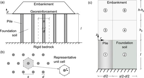
In this article, the authors considered the construction of GRPS embankments, and the problem schematised in is reduced to the analysis of one central axisymmetric cell (). The unit cell of diameter s, assumed to be equal to the pile spacing (different values can be considered in case of different pile dispositions) includes: (i) one pile of diameter d and length l, (ii) a homogeneous soft soil stratum of thickness l resting on a rigid bedrock, (iii) an embankment whose height h evolves during the construction process and (iv) the geosynthetic reinforcement laid at the embankment base. In this article, the pile shaft is assumed to be smooth and the construction process to take place under drained conditions.
Figure 1. GRPS embankment: (a) problem geometry and (b) representative unit cell. (c) Substructuring for both CPS and GRPS embankments.
As observed by di Prisco et al. (Citation2020a), during the construction of CPS embankments, due to the difference in stiffness between pile and foundation soil, differential displacements accumulate at the embankment base. Consequently, (i) strains localize in the proximity of the pile edge, (ii) differential settlements are expected to develop at the embankment top and (iii) stresses tend to migrate towards the piles (‘arching effect’). In more detail:
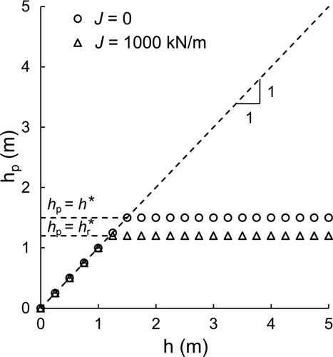
due to the progressive evolution of the embankment height (geometric non-linearity), shear strains localize in a cylindrical narrow crown close to the pile edge (process zone), whose height (hp), initially equal to the embankment height (hp = h), stops evolving when the embankment height becomes sufficiently large (h = hp = h*);
differential settlements at the embankment top develop for h < h*, whereas for h > h* their increments due to embankment construction nullify. Therefore, h* can be assumed to coincide with the position of the plane of equal settlements (Terzaghi, Citation1943; McKelvey, Citation1994; Naughton, Citation2007; McGuire, Citation2011; di Prisco et al., Citation2020a);
vertical stresses at the embankment base are not uniform, for r < d/2 (being r the radial coordinate defined in ) they are significantly larger than the ones for r > d/2. This difference markedly decreases within the embankment body towards the top and nullifies for z = h* (being z the vertical coordinate defined in ), where vertical stresses practically coincide with the geostatic ones.
According to the numerical results obtained by di Prisco et al. (Citation2020a) for CPS embankments, h* depends on geometry (s and d) and materials properties (i.e. embankment and foundation soil stiffness, and embankment soil friction and dilatancy angle values). The evolution of h* and all mechanical processes taking place in the embankment body are severely affected by the construction process. For this reason, all the theoretical approaches, experimental tests and numerical analyses results obtained by assuming a non-evolving embankment geometry (Terzaghi, Citation1936; Iglesia, Citation1991; Zaeske, Citation2001; Han & Gabr, Citation2002; Stewart & Filz, Citation2005; Yan et al., Citation2006; Dewoolkar et al., Citation2007; Chen, et al., Citation2008a; Chen et al., Citation2008b; Van Eekelen et al., Citation2012b, Citation2012a; Iglesia et al., Citation2014; Rui et al., Citation2019; Almeida et al., Citation2020) cannot be considered to be representative for the problem discussed in this article.
To simplify the interpretation of the mechanical processes taking place in the system, by following a substructuring approach, di Prisco et al. (Citation2020a) introduced for CPS embankments a subdivision of the system in six subdomains (): 1) the pile; 2) the foundation soil; 3) the embankment for 0 < r < d/2 and 0 < z < hp; 4) the embankment for d/2 < r < s/2 and 0 < z < hp, where the arching effect develops; 5) the embankment for 0 < r < d/2 and hp < z < h; 6) the embankment for d/2 < r < s/2 and hp < z < h. This substructuring is the same as for GRPS embankments, as it will be discussed in Section 4.1.The height of subdomains representing the embankment (subdomains 3 to 6) evolves during construction with both h and hp, introducing a geometrical non-linearity in the problem. This substructuring procedure is particularly convenient since it can simply be extended to take into account floating piles, hydromechanical coupling and rough pile shafts (Flessati et al., Citation2022).
The geosynthetic layers positioned at the embankment base, behaving as membranes (i.e. their flexural stiffness is negligible) under large displacements, are expected to reduce both settlements (at the embankment base and top) and h*. This reduction is expected to be governed by the geosynthetic-foundation soil relative stiffness ratio: by increasing this ratio smaller both displacements and h* are expected. During the embankment construction, tensile stresses are expected to develop in the reinforcement, influenced by both system geometry and material mechanical properties (embankment and foundation soil stiffness, embankment soil friction and dilatancy angle values and reinforcement stiffness).
In this article, the authors, by discussing the results of a series of large-displacement FD numerical analyses and by interpreting them with the use of the previously mentioned substructuring approach, intend to highlight the influence of geosynthetic reinforcements on the evolution of (i) stress redistribution in the embankment body, (ii) displacement field, (iii) process height and (iv) reinforcement tensile force.
3. Numerical model
The unit cell of has been numerically modelled () by means of a FD numerical code (FLAC3D version 6.0, Itasca, Citation2017). A large displacement approach has been chosen and the spatial discretisation has been optimised with the aim of improving the results accuracy.
Figure 2. Numerical model and spatial discretization.
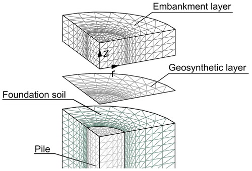
Pile, foundation soil and embankment layers have been discretised by means of 2400, 5120 and 480 brick-type zones, respectively. Normal displacements are not allowed along both lateral boundaries and base. The pile is assumed to be elastic and analogously to what often done by many other authors (Han & Gabr, Citation2002; Stewart & Filz, Citation2005; Yan et al., Citation2006; Liu et al., Citation2007; Chen, et al., Citation2008a; Chen et al., Citation2008b; Ariyarathne et al., Citation2013; Lehn et al., Citation2016; Zheng et al., Citation2019; Zhuang et al., Citation2020), the soil behaviour has been modelled by means of a non-associated elastic-perfectly plastic constitutive relationship with a Mohr-Coulomb failure criterion. According to the authors, this constitutive relationship, despite of its simplicity, can capture the main aspects of the mechanical processes taking place in the domain. Therefore, the results obtained by employing more sophisticated constitutive relationships, for instance strain hardening elastic-plastic constitutive models (di Prisco et al., Citation1993; Manzari & Dafalias, Citation1997; Dafalias & Manzari, Citation2004; Marveggio et al., Citation2022), are not expected to be qualitatively different. It is also worth mentioning that, for practical applications, sophisticated constitutive relationships, although more reliable in reproducing the material response, very often cannot be properly calibrated owing to the lack of a sufficient number of laboratory/in situ tests data.
As done by other authors (Han & Gabr, Citation2002; Stewart & Filz, Citation2005; Yan et al., Citation2006; Han et al., Citation2007; Liu et al., Citation2007; Huang & Han, Citation2010; van Eekelen et al., Citation2011; Yapage & Liyanapathirana, Citation2014; Lehn et al., Citation2016; Zhuang et al., Citation2020; Wijerathna & Liyanapathirana, Citation2020) the geosynthetic reinforcement has been modelled as an elastic isotropic membrane (the flexural stiffness is therefore neglected) of axial tensile stiffness J. This choice is justified by the presence of the underneath (isotropic) soil and to the transversal loads applied to the reinforcements (Boschi et al., Citation2020, Citation2021).
Between pile and foundation soil, smooth interface elements are introduced. Along normal direction, under compression, the interface elements are ‘quasi rigid’ (the elastic stiffness is sufficiently larger than the soil one, equal to 4e5 kN/m3), whereas under tension perfectly fragile.
Between the geosynthetic and the surrounding soil, frictional interface elements quasi-rigid along the normal direction are introduced. The interface friction angle is imposed to be equal to the soil one (in agreement with the experimental findings of Liu et al., Citation2009a; Liu et al., Citation2009b); Moraci et al. (Citation2014)).
In contrast with what already done by Han and Gabr (Citation2002) and Jennings and Naughton (Citation2012), who analysed the embankment mechanical response to additional vertical loads after the embankment construction for different embankment heights, in this study, the embankment construction process is numerically simulated. This implies that a comparison of the numerical results illustrated here in the following with what obtained by the previously mentioned authors is possible only by considering the incremental response of the system (see Section 4.2). The layer-by-layer embankment construction is subdivided in single stages, each one corresponding with the deposition of 25 cm of compacted granular material (for the sake of simplicity, the ground surface levelling is not reproduced). At each construction stage, a new stratum of elements is added on the current position of the embankment top. This allows to reproduce although in a simplified way, the real loading path followed by the system during the embankment construction.
4. Reference case
To highlight the mechanical processes taking place during the embankment construction, the authors performed a parametric study. However, for the sake of clarity, in this section, the main aspects of the system response are discussed by comparing a reference case of GRPS embankment (with J = 1000 kN/m), with the corresponding CPS one (J = 0) from di Prisco et al. (Citation2020a) . The results of the parametric study are presented in Section 5.
The system geometry and the materials mechanical properties for the reference case are reported in and , respectively.
Table 1. Reference case geometry for both GRPS and CPS embankments.
Table 2. Reference case mechanical properties for both GRPS and CPS embankments.
In the variation, during the embankment construction, of vertical stress (σv) along the radial coordinate r at z = 0 is reported: refers to the reinforced case below the membrane, whereas to the unreinforced one.
Figure 3. Variation of vertical stress along the radial coordinate for z = 0: (a) GRPS embankment, below the geosynthetic reinforcement and (b) CPS embankment.
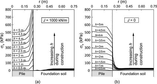
As was expected, in both unreinforced and reinforced case the arching mechanism, deviating vertical stresses towards the pile, develops during the embankment construction and, for a fixed embankment height, it is more effective in the reinforced case (see also Section 4.2). As already observed in Han and Gabr (Citation2002), the presence of the membrane severely also affects the shape of the stress profile: both an increase in vertical stress at the edge of the pile and a decrease in the foundation soil crown adjacent to the pile are evident in the reinforced case (). This is due to a reduction in the differential settlement at the embankment base, as is discussed in the following, and to the transfer mechanism of vertical stresses from the reinforcement ().
Figure 4. Numerical results of GRPS reference embankment in terms of: (a) vertical stress acting above the membrane and (b) net vertical stress acting on the membrane along the radius for different values of embankment height.
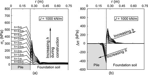
In fact, the presence of the membrane severely influences the shape of the vertical stress profiles above the membrane (z = 0 ): the σv curves for d/2 < r < s/2 are characterised by a well-pronounced peak in the proximity of the pile edge, absent in the unreinforced case (). This peak depends on the reinforcement stiffness, but the corresponding results are here omitted for the sake of brevity. The difference in vertical stresses above and below the membrane (Δσ), representing the ‘net’ vertical stress acting on the membrane, is characterised by two opposite peaks (one external and the other internal to the pile) and is practically nil for both small (r < 0.3d) and large (r > d) r values (). This net distribution is very similar to the one experimentally observed by Briançon and Simon (Citation2012).
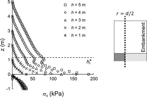
The large values of Δσ of in the proximity of the pile edge (r > d/2) cause a discontinuity for z = 0 in the distribution of σv along z ().
Figure 5. Reinforced reference case: distribution for r = d/2 of vertical stress for different h values.
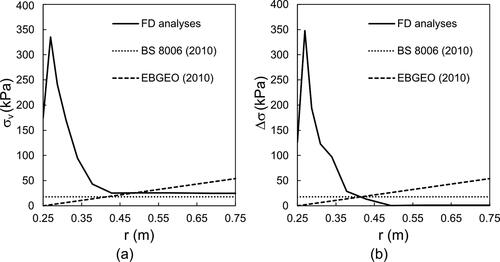
For the sake of completeness, in the numerical stress distribution above the membrane () and the Δσ distribution () for h = 5 m are compared with the ones calculated by employing the approaches suggested in the most popular design standards (BS8006-1, Citation2010; EBGEO, Citation2010). According to these approaches, for the sake of simplicity: (i) σv = Δσ, since, under the reinforcement, the presence of the soil is disregarded and (ii) the relative stiffness of the various elements of the geo-structure (embankment, foundation soil, geosynthetic and pile) is not accounted for. As is evident from , the numerically calculated spatial distribution of vertical stresses on geosynthetic is not captured by the distributions assumed by the standards neither in amplitude nor in shape.
Figure 6. Comparison for the reference case between the current standards and the FD analyses of GRPS embankment in FLAC3D for h = 5 m in terms of both (a) σv acting above the geosynthetic reinforcement and (b) net vertical stress, Δσ, against the radial coordinate.
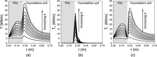
The distribution in the membrane of the tensile force per unit length T along r, corresponding to the vertical stress distribution in , is plotted for different embankment height values in . The trend of T with r is very similar to the one already obtained by Han and Gabr (Citation2002). However, Han and Gabr (Citation2002) used fully bonded interfaces between piles and soil and geosynthetics and soil. As a consequence, the T trend for r < d/2 is slightly different from the one obtained in this study, where a smooth interface between the pile shaft and the soil is considered, as well as a geosynthetic – embankment soil frictional interface. The maximum T value (Tmax) is reached close to r = d/2 and, after the peak, T rapidly decreases. Consistently with the vertical distribution of Δσ (), for r > d/2, the spatial distribution of the vertical component of T (Tz in ) is characterised by a peak in the proximity of the pile, whereas rapidly decreases for r > d/2, where the horizontal component of T (Tr in ) governs the T trend of .
Figure 7. Variation of the tensile force (a) T in the geosynthetic reinforcement and of its (b) vertical and (c) horizontal components along the radius for different embankment height values.
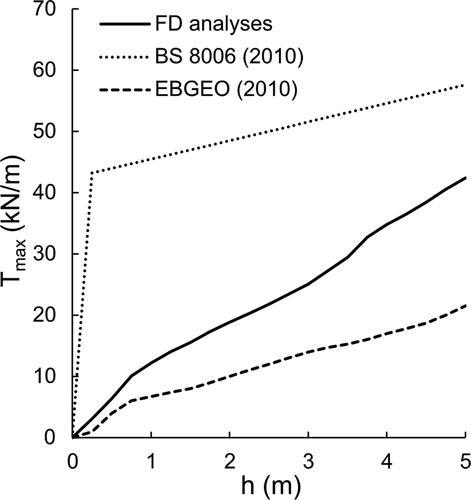
The corresponding evolution of Tmax with h is plotted in (solid line). The change in the curve inclination (‘knee’ of the curve) testifies the arch effect formation, as it will be discussed here in the following. Again, very instructive is the comparison with the curves obtained by employing the equations suggested by both BS8006-1 (Citation2010) and EBGEO (Citation2010). The BS8006-1 curve, obtained by choosing a design strain of 5% (Pham & Dias (Citation2021)) markedly overestimates the tensile force for any h values. In contrast, the EBGEO curve seems to capture the numerical results for very small values of h, but underestimate them for h > 0.5 m.
Figure 8. Comparison between different standards and FD analyses results in terms of maximum tensile force in the geosynthetic against height of the embankment.
The presence of the membrane also severely influences the shape of the settlement (ub) profile at the embankment base if compared to the unreinforced case (, referring to reinforced and unreinforced case, respectively). In the reinforced case, the ub profile, coincident with the membrane-deformed shape, is continuous and characterised by an upward concavity and is almost constant for r > 0.9d. This ub profile is due to the distribution of net vertical stresses Δσ illustrated in and does not coincide with the parabolic profile that would be obtained by employing BS8006-1 (2010), assuming a uniform pressure distribution along r ().
Figure 9. Settlement profile at the embankment base for both (a) the reinforced and (b) the unreinforced reference case.
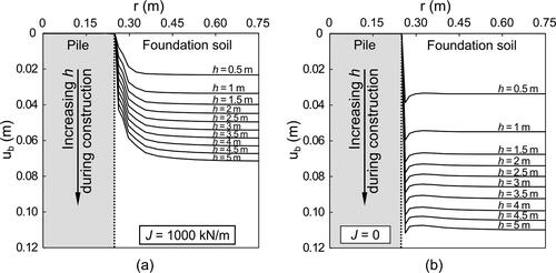
The settlements at the embankment top (ut) are reported in for both reinforced and unreinforced cases (, respectively). Since geometry is evolving during the embankment construction, settlements at the embankment top are calculated as:
where zt (r) is the position of ground surface, evolving (like h) during the embankment construction. In , the dashed lines represent different h values, whereas the solid lines
are not the settlement induced by each loading step (that is the positioning of each soil stratum), but represents the cumulative settlement at ground surface evolving during construction.
Figure 10. Settlement profile at the embankment top for (a) the reinforced and (b) the unreinforced reference case.
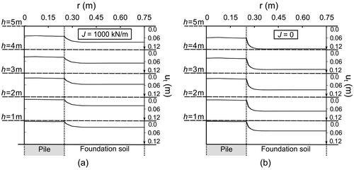
As was expected, the reinforcement reduces both the mean and differential settlement values.
For the reinforced case, both vertical stress and displacement (u) profiles along r are reported in for different z values at the end of construction (h = 5 m).
Figure 11. Numerical results of GRPS reference embankment in terms of: profiles of (a) vertical stress and (b) vertical displacement for different values of z; contour plot of both (c) vertical stress and (d) settlements in z = 0.
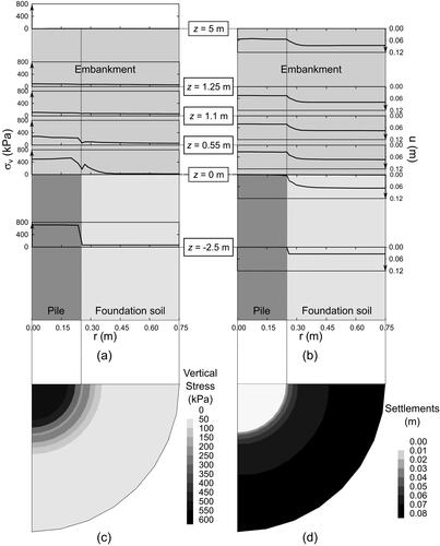
For negative z values (for the sake of clarity in only z = − 2.5 m is reported), both σv and u are uniform within both pile (0 < r < d/2) and foundation soil (d/2 < r < s/2). In contrast, for 0 < z < 1.1 m and 0.5 < r/d < 0.6 (that is, close to the pile edge), the arching effect makes both σv and u not uniform. This variation is clearly shown for z = 0 in .
For z > 1.1 m, σv is almost constant with r, and u does not change with z, since the thickness of 1.1 m is sufficient for the formation of the arching effect.
The evolution of irreversible deviatoric strain contours with h for the reinforced case is illustrated in . In both reinforced and unreinforced case (for the sake of brevity the results relative to the unreinforced case are omitted, but can be found in di Prisco et al., Citation2020a), deviatoric strains are localised in a cylindrical crown (defined in di Prisco et al., Citation2020a as ‘process zone’) close to the pile edge, while in the rest of the spatial domain deviatoric strains are negligible, implying the remaining spatial domain to be under pseudo-oedometric conditions and, therefore, according to the employed constitutive relationship, the soil to behave elastically.
Figure 12. Progressive evolution of deviatoric strains in the GRPS reference embankment during construction.
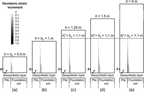
For small h values, the height of the process zone (hp) coincides with the embankment height, but, when the embankment height gets a threshold value (hp = hr* = 1.1 m), hp stops evolving. For both reinforced and unreinforced cases, the evolution of hp with h is plotted in : the trend is very similar, but the final value of hp for the unreinforced case (h*) is larger than hr*. According to di Prisco et al., Citation2020a, h* is a function of geometry (s, d and l), soil friction and dilatancy angle and the relative stiffness between pile, foundation soil and embankment soil. In the reinforced case, as it will be shown in Section 5, it also depends on J.
Figure 13. Evolution of the height of the process zone (process height) during construction.
4.1. Discussion of the arching effect
As is well-known, the response of GRPS embankments is dominated by the arching effect, that, according to the interpretation/substructuring suggested by the authors, develops progressively during the embankment construction in subdomain 4 of . In this subdomain vertical stresses are not uniform (see results in for h = 5 m, i.e. hp = hr*). In particular, at the base of the embankment, i.e. for z = 0 (solid line of ), vertical stresses are significantly larger close to the pile edge r = d/2 with respect to the ones for r = s/2. This difference markedly decreases for larger z values (dotted line of ) and nullifies for z = hr*, that is at the plane of equal settlement. At this depth, which is the boundary between subdomain 4 and 6 in , the vertical stress value practically coincides with the geostatic one (equal to γ(h-z), being γ the unit weight of the embankment soil).
Figure 14. Numerical results of GRPS reference embankment, for h = 5 m, in terms of: (a) contour plot of vertical stresses in subdomain 4 of the embankment, (b) vertical stress profiles for z = 0, z = hr*/2 and z = hr*, (c) contour plot of shear stresses in subdomain 4 of the embankment, (d) shear stress profiles for z = 0, z = hr*/2 and z = hr*.
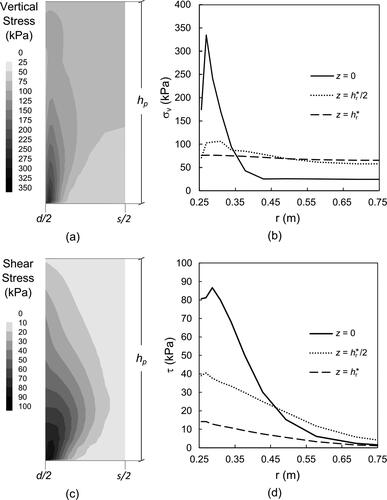
As is expected, the redistribution of vertical stresses is associated with the arising of shear stresses (τ) in the z - r plane in subdomain 4 (). For any z value, τ gets its maximum value close to r = d/2 (). Even if for z = hr* vertical stresses are almost uniform, shear stresses are not nil but their value is negligible with respect to the correspondent vertical stresses.
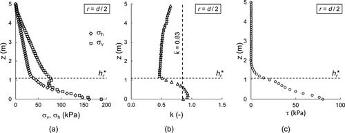
The arching effect mainly develops in subdomain 4, that is for z < hr*. This is also evident by the trend along z for r = d/2 of
(horizontal stresses),
and τ (, respectively). For z > hr*, the vertical stress distribution is linear and practically coincident with the geostatic one, whereas τ practically negligible. For z slightly larger than hr*, τ starts increasing due to the previously mentioned localisation of shear strains taking place in the process zone. For 0 < z < hr*, that is in the process zone, (i) both
and
stop increasing linearly with depth, (ii)
starts increasing and (iii) τ gets very large values.
Figure 15. Numerical results of GRPS reference embankment, for h = 5 m, in terms of (a) vertical and horizontal stress; (b) k ratio and (c) tangential stresses within the embankment for r = d/2.
The role of the geometrical evolution of the embankment, described by the progressive increase in h, has been already mentioned in Section 2. Hereafter, the development of the arching effect within the embankment is illustrated, for
and
(, respectively), by plotting against
the vertical stress, normalised with respect to
In this non-dimensional plane, geostatic conditions coincide with a vertical straight line
For 0 < z/d < hr*/d, due to the development of the arching effect, vertical stresses significantly differ from the geostatic ones. In this zone, all the curves corresponding to h > hr* (only the curve with asterisks in is not in this range, since for the reference case hr* = 1.1 m, see ) are practically coincident, testifying that the arching effect is mature.
Figure 16. Numerical results of GRPS reference embankment in terms of variation of vertical stresses along z for: a) r = 0, b) r = (s-d)/2 and c) r = s/2.
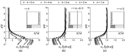
The numerical results demonstrate that, for h > hr*, that is when the arching effect is mature, vertical stresses on the foundation soil linearly increase with h and, in fact, data of are not coincident for −2 < z/d < 0. This testifies that, due to the embankment deformability , a "full arching" mechanism, totally transferring vertical stresses to the piles (van Eekelen et al. Citation2011), does not develop (di Prisco et al., 2020a).
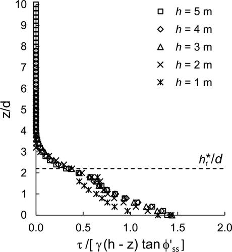
Particularly interesting is the evolution during construction of the distribution along z/d of normalised shear stresses being
the embankment soil friction angle under simple shear (Vermeer, Citation1990; Drescher & Detournay, Citation1993; di Prisco & Pisano, Citation2011; Pisanò et al., Citation2016; di Prisco et al., Citation2020a; di Prisco & Flessati, Citation2021). In the non-dimensional plane (), for h > hr* that is when the arching effect is mature, all the curves superimpose, and the normalised shear distribution reaches a sort of steady condition. In , three branches are evident: (i) for 0 < z/d < hr*/d (where irreversible strains develop) tangential stresses almost linearly increase with depth; (ii) for hr*/d < z/d < 4 (where the material behaves elastically, according to ) parabolically increase with depth and (iii) for z/d > 4 are practically nil.
Figure 17. Numerical results of GRPS reference embankment in terms of distribution of normalised tangential stresses within the embankment for r = d/2 during construction (different values of embankment height are considered).
4.2. Interpretation of the system response by means of non-dimensional variables
From an engineering point of view, with reference to , the system response may be described by means of: differential and average settlements at the top of the embankment, average vertical displacement at the base of subdomain 4 (ub,f), average stresses at the base of subdomain 4, calculated above and below the membrane ( and
respectively), and average stresses at the base of subdomain 3 (
average vertical stress on the concrete pile head).
By following what proposed in di Prisco et al. (Citation2020a), the mechanical response of the system is studied by employing a non-dimensional expression of these variables:
(1)
(1)
(2)
(2)
(3)
(3)
(4)
(4)
(5)
(5)
(6)
(6)
being ut,c and ut,f, the average vertical displacements at the top of subdomains 5 and 6 respectively, whereas Eoed,f the foundation soil oedometric elastic modulus.
As is suggested in di Prisco et al. (Citation2020a), the employment of these non-dimensional variables is particularly convenient since, in the non-dimensional Ut,diff - H (being H = h/d) and Ut,av - H planes, the unreinforced embankment response is unique if the non-dimensional geometrical ratios (s/d, l/d), the non-dimensional stiffness ratio (Eoed,e/Eoed,f, being Eoed,e the embankment soil oedometric modulus) and the embankment soil failure parameters (friction and dilatancy angle values, and
respectively) are kept constant.
The numerical results, relative to both GRPS and CPS embankments, in terms of variation with H of the non-dimensional displacement (Ut,diff, Ut,av and Ub,f) and stress (Σf,a and Σf,b) variables, are reported in .
Figure 18. Numerical results for both CPS and GRPS reference embankments in the non-dimensional a) Ut,diff - H, b) Ut,av - H, c) Ub,f - H, d) the - H and
- H and e)
- H planes.
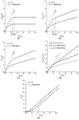
In both reinforced and unreinforced cases, the curves associated with differential settlements () are characterised by a downward concavity, testifying a progressive stiffening of the system. In the unreinforced case, this is due to the propagation of process zone (di Prisco et al., Citation2020a), whereas in the reinforced case to both the propagation of process zone and the progressive stiffening of the membrane (geometric non-linearity). At a certain H value, corresponding to the plane of equal settlements (Terzaghi, Citation1943; McKelvey, Citation1994; Naughton, Citation2007; McGuire, Citation2011; di Prisco et al., Citation2020a), differential settlements stop increasing. These two H values (Hr* and Hu*, for reinforced and unreinforced cases, respectively), coincide with the maximum height of the process zone (h*r/d and h*u/d of , respectively).
Initially, Ut,av and Ut,diff practically coincide () but for H > Hu* or Hr* the trend markedly differs since average settlements (Ut,av) continuously increase with H.
Ub,f in both reinforced and unreinforced cases continuously increase with H (), signature of a continuous increase in stresses () applied to the foundation soil and, as previously mentioned, of the absence of a ‘full arching mechanism’, totally deviating vertical stress increments towards the pile. For sufficiently high values of H, the curves tend to linearly increase, since stresses in the foundation soil tend to increase linearly with H, as is testified by .
In the unreinforced case whereas
in the reinforced case. Moreover,
in the reinforced case is smaller than
in the unreinforced case, although, owing to the increase in stiffness due to the presence of the membrane,
in the reinforced case is larger than in the unreinforced case (). The difference between
in the reinforced and in the unreinforced case () is a measure of the effectiveness of the reinforcement intervention in transferring stresses towards the pile. As was expected, the average vertical stress acting on the pile (
) is larger for the reinforced case, confirming that the geosynthetic reinforcement significantly contributes to transfer vertical stresses towards the pile ().
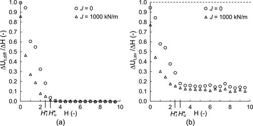
To further highlight the effectiveness of both piles and reinforcement to reduce the progressive accumulation of settlements during construction, the response of the embankment is illustrated in , in terms of increment of settlements (ΔUt,diff/ΔH and ΔUt,av/ΔH) vs H. The trend of ΔUt,diff/ΔH vs H, confirms the numerical results already obtained by other authors (Han & Gabr, Citation2002; Jennings & Naughton, Citation2012). In this study, the number of available data for different values of embankment height is quite large, if compared to the results by Han and Gabr (Citation2002) and Jennings and Naughton (Citation2012), since one numerical simulation (h = 5 m) provides 20 values (one for each 0.25 m thick layer). The final ΔUt,av/ΔH value for both CPS and GRPS reference embankments is of one order of magnitude smaller than the one corresponding to unreinforced embankment with no piles (dashed line in ). Such a reduction depends on geometry, materials stiffness and only slightly on soil embankment friction angle (as discussed in Section 5).
Figure 19. Numerical results for both CPS and GRPS reference embankments in terms of evolution of the increment of (a) differential settlements and (b) average settlements at the top of the embankment.
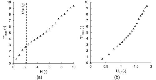
In the reinforced case, the non-dimensional maximum tensile force of the reinforcement:
(7)
(7)
is introduced. The evolution of T*max with H is plotted against both H and Ub,f (): T*max continuously increases with H and the H value associated with the inflection of the curve corresponds to Hr*.
Figure 20. Evolution of non-dimensional maximum tensile force in the geosynthetic reinforcement with a) non-dimensional embankment height and b) non-dimensional average settlement of the membrane, Ub,f.
5. Parametric study
In this section, the results of a parametric study are reported. In particular, the influence of (i) reinforcement stiffness; (ii) embankment soil mechanical properties (Young modulus Ee, ϕ’e and ψe; (iii) foundation soil mechanical properties (Young modulus Ef and friction angle ϕ’f) and (iv) geometry are discussed in , respectively.
Figure 21. Influence of reinforcement tensile axial stiffness, J, on non-dimensional: both a) differential and b) average settlements and c) maximum tensile force. d) Non-dimenisonal average settlement at the base of the embankment against non-dimensional geosynthetic axial stiffness for H = 10.
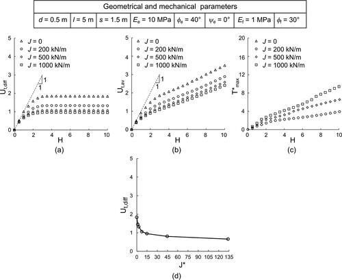
Figure 22. Influence of: embankment deformability on a) Ut,diff, b) Ut,ax, c) T*max; embankment soil friction angle on: d) Ut,diff, e) Ut,ax, f) T*max and embankment soil dilatancy angle on g) Ut,diff, h) Ut,ax, i) T*max.
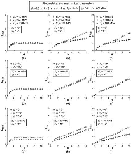
Figure 23. Influence of: foundation soil deformability on a) Ut,diff, b) Ut,ax, c) T*max and foundation soil friction angle on d) Ut,diff, e) Ut,ax, f) T*max.
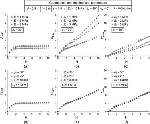
Figure 24. Influence of: foundation soil stratum thickness on a) Ut,diff, b) Ut,ax, c) T*max and influence of spacing on d) Ut,diff, e) Ut,ax, f) T*max.
As was expected, an increase in J, causes a decrease in both differential () and average settlements (), and an increment in the maximum tensile force in the membrane (). As already suggested by Han and Gabr (Citation2002), the effectiveness of the reinforcement is progressively decreasing with J. In fact, the reduction in differential settlements at the embankment base (above the foundation soil) associated with an increase in the reinforcement/foundation soil relative stiffness, defined as:
(8)
(8)
is progressively decreasing and is practically negligible for J* > 15 (, obtained for H = 10).
The embankment deformability slightly influences differential settlements (), but severely affects both Ut,av () and T*max (): stiffer embankments are associated with lower both average settlements and maximum tensile force values. The final slope of the linear branches of both Ut,av-H and T*max-H curves progressively decreases with the embankment stiffness. This confirms the observation referred to CPS embankments in di Prisco et al., Citation2020a, according to which, for sufficiently large Eoed,e values a full-arching mechanism develops and average vertical stress stops increasing.
The system response is very slightly affected by the embankment friction angle value (), as already observed by di Prisco et al. (Citation2020a), whereas, in contrast with what is commonly assumed by the simplified approaches mentioned in Section 1 (Marston, Citation1913; Terzaghi, Citation1936; Hewlett & Randolph, Citation1988; Russell & Pierpoint, Citation1997; van Eekelen et al., Citation2015), it is affected by the dilatancy angle value (): by increasing the dilatancy angle maximum tensile force in the reinforcement, differential and average displacements decrease.
In , the foundation soil mechanical properties are accounted for. T*max decreases by increasing Ef (); in an increase in the foundation soil stiffness, is associated with a decrease in Ut,diff and an increase in Ut,av. This unphysical result is only apparent, stemming from the non-dimensional variable definition: the corresponding dimensional average displacement ut,av value decreases by increasing Ef.
The influence of the foundation soil friction angle, ϕ'f, is plotted in , where for the sake of completeness the numerical results obtained by considering an elastic foundation soil are also reported. As is evident, the foundation soil friction angle value does not affect the system response, implying that irreversible strains do not develop in the foundation soil.
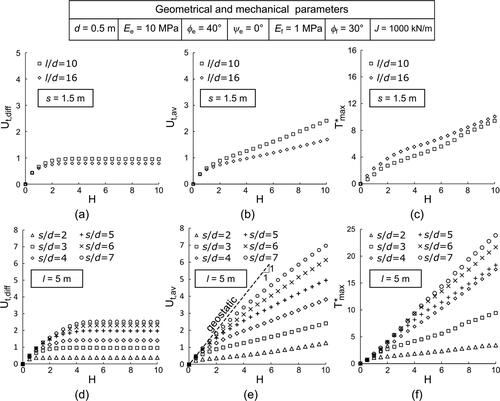
The thickness of the foundation soil stratum slightly affects the evolution of Ut,diff and T*max with H (). On the contrary, l influences the evolution of Ut,av but, due to the non-dimensional variable definitions, only for H > H*r (). H*r corresponds to the knees of the numerical results in the non-dimensional planes ().
As was expected, the pile spacing severely influences the system response (). By increasing s (i) both H*r and the final value of differential settlements increase (), (ii) average settlements increase and the curve associated with Ut,av becomes closer to the 1:1 inclined straight line () defining the geostatic case (i.e. when the arching effect is not taking place in the embankment) and (iii) the axial force in the geosynthetic reinforcement increases ().
6. Concluding remarks
In this article, the authors analysed the mechanical response of basal reinforced piled embankments by means of a series of 3D large displacement FD numerical analyses, simulating a layer-by-layer embankment construction under drained conditions, in which the geosynthetic reinforcement is modelled as an elastic membrane. The global mechanical response is described in terms of average/differential settlements at the top of the embankment and maximum tensile force in the geosynthetic reinforcement. The numerical results put in evidence that:
the presence of the membrane reduces settlements at both the embankment top and base;
the effectiveness of the reinforcement increases with the membrane/foundation soil relative stiffness;
for very large membrane/foundation soil relative stiffness an asymptotic value of effectiveness is reached. This implies that the use of very rigid membranes may become useless if not associated with a change in pile spacing;
the presence of the membrane increases the generalised stiffness of GRPS embankments after construction;
both stress and displacement distribution at the embankment base are affected by presence of the geosynthetic reinforcements, implying that, in contrast with the most popular design standards, the arching effect taking place in the embankment is significantly affected by the geosynthetic reinforcement stiffness;
the shape of the stress distribution acting on the membrane is significantly different with respect to that suggested in the current design standard;
the geosynthetic reinforcement mainly deforms close to the pile edge, whereas remains horizontal far from the piles;
the height of both process zone and plane of equal settlements varies according to the reinforcement tensile axial stiffness;
owing to the embankment deformability, a full-arching mechanism, deviating vertical stress increments towards the pile, does not develop;
the foundation soil is under pseudo-oedometric conditions and, according to the adopted constitutive relationship (without a ‘volumetric cap’), behaves elastically;
the system response is significantly influenced by the embankment soil dilatancy angle value, not considered in the simplified analytical models commonly employed to analyse the arching effect.
The numerical results obtained in this study (and the understanding of the mechanical processes occurring within the embankment, during embankment construction) are, according to the authors, very useful to: (i) design a proper experimental setup, in terms of both geometry and materials mechanical properties; (ii) individuate the most strategic points where measuring deformations and stresses and (iii) interpret the experimental data.
| List of symbols | ||
| CPS | = | conventional pile-supported |
| d | = | pile diameter |
| Eoed,e | = | embankment soil oedometric modulus |
| Eoed,f | = | foundation soil oedometric modulus |
| FD | = | finite difference |
| FE | = | finite elements |
| GRPS | = | geosynthetic-reinforcedand pile-supported |
| H | = | non-dimensional embankment height |
| h | = | embankment height |
| hp | = | height of the shear zone, process height |
| h* | = | dimensional critical embankment height for CPS embankments |
| H*u | = | non-dimensional critical embankment height for unreinforced (CPS) emabnkments |
| Hr* | = | non-dimensional critical embankment height for reinforced (GRPS) embankments |
| hr* | = | dimensional critical embankment height for GRPS embankments |
| J | = | geosynthetic tensile axial stiffness |
| J* | = | non-dimensional geosynthetic tensile axial stiffness or reinforcement/foundation soil relative stiffness |
| k | = | ratio between horizontal and vertical stresses |
| = | average value of k in the process zone () | |
| l | = | pile length and soft soil stratum thickness |
| s | = | pile spacing |
| r | = | radial coordinate () |
| T | = | tensile force (per unit length) within the geosynthetic |
| Tmax | = | maximum value of T |
| Tr | = | horizontal component of T |
| Tz | = | vertical component of T |
| T*max | = | non-dimensional maximum tensile force within the geosynthetic |
| u | = | vertical displacement |
| ub | = | embankment base settlement |
| Ub,f | = | non-dimensional average settlement of the base of the embankment over the foundation soil |
| ub,f | = | average settlement of the base of the embankment over the foundation soil |
| ut | = | cumulative settlement at the top of the embankment |
| Ut,av | = | non-dimensional embankment average settlement at the top of the embankment |
| ut,c | = | average displacement of the top of the embankment over the pile |
| Ut,diff | = | non-dimensional embankment top differential settlement |
| ut,f | = | average displacement of the top of the embankment over the foundation soil |
| z | = | vertical coordinate () |
| zt | = | vertical coordinates of the points representing the top of the embankment |
| γ | = | embankment soil unit weight |
| Δσ | = | net vertical stress transmitted to the geosynthetic reinforcement |
| Σc | = | non-dimensional average vertical stress above the concrete pile head |
| Σf,a | = | non-dimensional average vertical stress above the geosynthetic reinforcement |
| Σf,b | = | non-dimensional average vertical stress below the geosynthetic reinforcement |
| = | average vertical stress above the concrete pile head | |
| = | average vertical stress above the geosynthetic reinforcement | |
| = | average vertical stress below the geosynthetic reinforcement | |
| σh | = | horizontal stress |
| σv | = | vertical stress |
| τ | = | tangential stress |
| ϕ’e | = | embankment soil internal friction angle |
| ϕ’f | = | foundation soil internal friction angle |
| ϕ’ss | = | embankment soil friction angle under simple shear |
| = | embankment soil dilatancy angle | |
Acknowledgements
All the numerical results have been obtained by using the commercial code FLAC3D™ within the framework of the Itasca Education Partnership (IEP) program. The authors would like to acknowledge Itasca Consulting Group and Harpaceas, which collectively provide the software licence. Dr. Viviana Mangraviti gratefully acknowledges the support of the project #98335 NordicLink.
Disclosure Statement
No potential conflict of interest was reported by the authors.
Data availability statement
Some or all data, models or code that support the findings of this study are available from the corresponding author upon reasonable request.
References
- Abdullah, C. H., & Edil, T. B. (2007). Numerical analysis of catenary load transfer platform for geopier-supported embankment. Advances in Measurement and Modeling of Soil Behavior, Proceedings. DOI: 10.1061/40917(236)11
- Almeida, M. S. S., Fagundes, D. F., Thorel, L., & Blanc, M. (2020). Geosynthetic-reinforced pile-embankments: Numerical, analytical and centrifuge modelling. Geosynthetics International, 27, 301–314. DOI: 10.1680/jgein.19.00011
- Ariyarathne, P., Liyanapathirana, D. S., & Leo, C. J. (2013). Effect of geosynthetic creep on reinforced pile-supported embankment systems. Geosynthetics International, 20, 421–435. DOI: 10.1680/gein.13.00029
- Boschi, K., di Prisco, C., Flessati, L., Galli, A., & Tomasin, M. (2020). Punching tests on deformable Facing structures: Numerical analyses and mechanical interpretation. Lecture notes in civil engineering. Springer International Publishing. DOI: 10.1007/978-3-030-21359-6_45
- Boschi, K., di Prisco, C., Flessati, L., & Mazzon, N. (2021). Numerical analysis of the mechanical response of anchored wire meshes. Lecture notes in civil engineering. Springer International Publishing. DOI: 10.1007/978-3-030-64518-2_92
- Briançon, L., & Simon, B. (2012). Performance of pile-supported embankment over soft soil: Full-scale experiment. Journal of Geotechnical and Geoenvironmental Engineering, 138, 551–561. DOI: 10.1061/(ASCE)GT.1943-5606.0000561
- BS8006-1. (2010). Code of practice for strengthened/reinforced soils and other fills. Sect. 8 (pp. 160-209). British Standards Institution.
- Carlsson, B. (1987). Reinforced soil, principles for calculation. Terratema AB. (in Swedish).
- Chen, R. P., Chen, Y. M., Han, J., & Xu, Z. Z. (2008a). A theoretical solution for pile-supported embankments on soft soils under one-dimensional compression. Canadian Geotechnical Journal, 45, 611–623. DOI: 10.1139/T08-003
- Chen, Y. M., Cao, W. P., & Chen, R. P. (2008b). An experimental investigation of soil arching within basal reinforced and unreinforced piled embankments. Geotext Geomembranes, 26, 164–174. DOI: 10.1016/j.geotexmem.2007.05.004
- Dafalias, Y. F., & Manzari, M. T. (2004). Simple plasticity sand model accounting for fabric change effects. Journal of Engineering Mechanics. 130, 622–634. DOI: 10.1061/(ASCE)0733-9399(2004)130:6(622)
- Almeida, M. S.S., Ehrlich, M., Spotti, A. P., & Maroues, M. E. S. (2007). Embankment supported on piles with biaxial geogrids. Proceedings of the Institution of Civil Engineers: Geotechnical Engineering, 160, 185–192. DOI: 10.1680/geng.2007.160.4.185
- Dewoolkar, M. M., Santichaianant, K., & Ko, H. Y. (2007). Centrifuge modeling of granular soil response over active circular trapdoors. Soils Found, 47, 931–945. DOI: 10.3208/sandf.47.931
- di Prisco, C., & Flessati, L. (2021). Progressive failure in elastic-viscoplastic media: From theory to practice. Geotechnique, 71, 153–169. DOI: 10.1680/jgeot.19.P.045
- di Prisco, C., Flessati, L., Frigerio, G., & Galli, A. (2020a). Mathematical modelling of the mechanical response of earth embankments on piled foundations. Geotechnique, 70, 755–773. DOI: 10.1680/jgeot.18.P.127
- di Prisco, C., Flessati, L., Galli, A., & Mangraviti, V. (2020b). A simplified approach for the estimation of settlements of earth embankments on piled foundations. In: Calvetti, F., Cotecchia, F., Galli, A., Jommi, C. (Eds.), Lecture notes in civil engineering (pp. 640–648). Springer International Publishing. DOI: 10.1007/978-3-030-21359-6_68
- di Prisco, C., Nova, R., & Lanier, J. (1993). A mixed isotropic-kinematic hardening constitutive law for sand. Modern approaches to plasticity. Elsevier. DOI: 10.1016/B978-0-444-89970-5.50010-8
- di Prisco, C., & Pisano, F. (2011). An exercise on slope stability and perfect elastoplasticity. Geotechnique, 61, 923–934. DOI: 10.1680/geot.9.P.040
- Drescher, A., & Detournay, E. (1993). Limit load in translational failure mechanisms for associative and non-associative materials. Geotechnique, 43, 443–456. DOI: 10.1680/geot.1993.43.3.443
- EBGEO. (2010). Empfehlungen für den entwurf und die berechnung von erdkörpern mit bewehrungen aus geokunststoffen. EBGEO. DOI: 10.1002/9783433600597
- Fagundes, D. F., Almeida, M. S. S., Thorel, L., & Blanc, M. (2017). Load transfer mechanism and deformation of reinforced piled embankments. Geotext Geomembranes, 45, 1–10. DOI: 10.1016/j.geotexmem.2016.11.002
- Filz, G., Sloan, J., McGuire, M. P., Collin, J., & Smith, M. (2012). Column-supported embankments: Settlement and load transfer. In Proc.: GeoCongress 2012. Oakland, California, United States (pp. 54–77). American Society of Civil Engineers. DOI: 10.1061/9780784412138.0003
- Filz, G. M., Sloan, J. A., McGuire, M. P., Smith, M., & Collin, J. (2019). Settlement and vertical load transfer in column-supported embankments. Journal of Geotechnical and Geoenvironmental Engineering, 145. DOI: 10.1061/(ASCE)GT.1943-5606.0002130
- Filz, G. M., & Smith, M. E. (2006). Final contract report design of bridging layers in geosynthetic-reinforced, column-supported embankments. Report Prepared for Virginia Department of Transport. https://vtechworks.lib.vt.edu/handle/10919/46681
- Flessati, L. (2021). Application of an innovative displacement based design approach for earth embankments on piled foundations. In: Barla, M., Di Donna, A., Sterpi, D. (Eds.), Lecture notes in civil engineering (pp. 293–299). Springer International Publishing. DOI: 10.1007/978-3-030-64518-2_35
- Flessati, L., di Prisco, C., Corigliano, M., & Mangraviti, V. (2022). A simplified approach to estimate settlements of earth embankments on piled foundations: The role of pile shaft roughness. European Journal of Environmental and Civil Engineering, 27, 194–214. DOI: 10.1080/19648189.2022.2035259
- Girout, R., Blanc, M., Thorel, L., & Dias, D. (2018). Geosynthetic reinforcement of pile-supported embankments. Geosynthetics International, 25, 37–49. DOI: 10.1680/jgein.17.00032
- Girout, R., Blanc, M., Thorel, L., Fagundes, D. F., & Almeida, M. S. S. (2016). Arching and deformation in a piled embankment: Centrifuge tests compared to analytical calculations. Journal of Geotechnical and Geoenvironmental Engineering, 142, 04016069. DOI: 10.1061/(ASCE)GT.1943-5606.0001557
- Han, J., & Gabr, M. A. (2002). Numerical analysis of geosynthetic-reinforced and pile-supported earth platforms over soft soil. Journal of Geotechnical and Geoenvironmental Engineering, 128, 44–53. DOI: 10.1061/(ASCE)1090-0241(2002)128:1(44)
- Han, J., Oztoprak, S., Parsons, R. L., & Huang, J. (2007). Numerical analysis of foundation columns to support widening of embankments. Computers and Geotechnics, 34, 435–448. DOI: 10.1016/j.compgeo.2007.01.006
- Hewlett, B. W., & Randolph, M. (1988). Analysis of piled embankments. GR Engineering, 21, 3–7.
- Hoppe, E. J., & Hite, S. L. (2006). Performance of a pile-supported embankment. Research report. http:/www.virginiadot.org/vtrc/main/online_reports/pdf/06-r36.pdf
- Huang, J., & Han, J. (2009). 3D coupled mechanical and hydraulic modeling of a geosynthetic-reinforced deep mixed column-supported embankment. Geotext Geomembranes, 27, 272–280. DOI: 10.1016/j.geotexmem.2009.01.001
- Huang, J., & Han, J. (2010). Two-dimensional parametric study of geosynthetic-reinforced column-supported embankments by coupled hydraulic and mechanical modeling. Computers and Geotechnics, 37, 638–648. DOI: 10.1016/j.compgeo.2010.04.002
- Iglesia, G. R. (1991). Trapdoor experiments on the centrifuge–a study of arching in geomaterials and similitude in geotechnical models. Massachusetts Institute of Technology. http://hdl.handle.net/1721.1/113811
- Iglesia, G. R., Einstein, H. H., & Whitman, R. V. (2014). Investigation of soil arching with centrifuge tests. Journal of Geotechnical and Geoenvironmental Engineering, 140. DOI: 10.1061/(ASCE)GT.1943-5606.0000998
- Itasca. (2017). FLAC3D v.6.0—fast Lagrangian analysis of continua in three dimensions. User manual. Itasca Consulting Group, Inc. Minnesota, United States of America.
- Jennings, K., & Naughton, P. J. (2012). Similitude conditions modeling geosynthetic-reinforced piled embankments using FEM and FDM techniques. ISRN Civil Engineering, 2012, 1–16. DOI: 10.1061/(ASCE)GT.1943-5606.0000998
- King, D. J., Bouazza, A., Gniel, J. R., Rowe, R. K., & Bui, H. H. (2017). Serviceability design for geosynthetic reinforced column supported embankments. Geotext Geomembranes, 45, 261–279. DOI: 10.1016/j.geotexmem.2017.02.006
- Ladanyi, B., & Hoyaux, B. (1969). A study of the trap-door problem in a granular mass: Discussion. Canadian Geotechnical Journal, 6, 441–443. DOI: 10.1139/t69-044
- Lai, H. J., Zheng, J. J., Zhang, R. J., & Cui, M. J. (2018). Classification and characteristics of soil arching structures in pile-supported embankments. Computers and Geotechnics, 98, 153–171. DOI: 10.1016/j.compgeo.2018.02.007
- Lehn, J., Moormann, C., & Aschrafi, J. (2016). Numerical investigations on the load distribution over the geogrid of a basal reinforced piled embankment under cyclic loading. Procedia Engineering, 149, 435–444. DOI: 10.1016/j.proeng.2016.06.055
- Liu, C. N., Zornberg, J. G., Chen, T. C., Ho, Y. H., & Lin, B. H. (2009a). Behavior of geogrid-sand interface in direct shear mode. Journal of Geotechnical and Geoenvironmental Engineering, 135, 1863–1871. DOI: 10.1061/(asce)gt.1943-5606.0000150
- Liu, C. N., Ho, Y. H., & Huang, J. W. (2009b). Large scale direct shear tests of soil/PET-yarn geogrid interfaces. Geotext Geomembranes, 27, 19–30. DOI: 10.1016/j.geotexmem.2008.03.002
- Liu, H. L., Ng, C. W. W., & Fei, K. (2007). Performance of a geogrid-reinforced and pile-supported highway embankment over soft clay: Case study. Journal of Geotechnical and Geoenvironmental Engineering, 133, 1483–1493. DOI: 10.1061/(asce)1090-0241(2007)133:12(1483)
- Low, B. K., Tang, S. K., & Choa, V. (1994). Arching in piled embankments. Journal of Geotechnical Engineering, 120, 1917–1938. DOI: 10.1061/(ASCE)0733-9410(1994)120:11(1917)
- Mangraviti, V. (2021). Theoretical modelling of embankments based on piled foundations. PhD Thesis, Milano, 12 May, 2021,
- Mangraviti, V., Flessati, L., & Di Prisco, C. (2022). A rheological model for georeinforced embankments based on piled foundations. IOP Conference Series: Materials Science and Engineering, 1260(1), 012014 10.1088/1757-899X/1260/1/012014
- Mangraviti, V. (2022). Displacement-based design of Geosynthetic-Reinforced Pile-Supported embankments to increase sustainability. In: Civil and Environmental Engineering for Sustainable Development Goals: emerging issues. Antonelli, M., Della Vecchia, G. (Eds.). Springer International Publishing, Cham, pp. 83–96. DOI: 10.1007/978-3-030-99593-5_7
- Mangraviti, V., Flessati, L., & di Prisco, C. (2021). Modelling the development of settlements of earth embankments on piled foundations. In: Barla, M., Di Donna, A., Sterpi, D. (Eds.), Lecture notes in civil engineering (pp. 811–816). Springer International Publishing. DOI: 10.1007/978-3-030-64518-2_96
- Manzari, M. T., & Dafalias, Y. F. (1997). A critical state two-surface plasticity model for sands. Geotechnique, 47, 255–272. DOI: 10.1680/geot.1997.47.2.255
- Marston, A. (1913). The theory of loads on pipe in ditches and tests of cement and clay drain tile and sewer pipe. Iowa State College of Agriculture and Mechanic Arts.
- Marveggio, P., Redaelli, I., & di Prisco, C. (2022). Phase transition in monodisperse granular materials: How to model it by using a strain hardening visco-elastic-plastic constitutive relationship. International Journal for Numerical and Analytical Methods in Geomechanics, 46, 2415–2445.
- McGuire, M. P. (2011). Critical height and surface deformation of column-supported embankments. Virginia Polytechnic Institute and State University. https://theses.lib.vt.edu/theses/available/etd-11142011-113910/
- McKelvey, J. A. (1994). The anatomy of soil arching. Geotext Geomembranes, 13, 317–329. DOI: 10.1016/0266-1144(94)90026-4
- Moraci, N., Cardile, G., Gioffrè, D., Mandaglio, M. C., Calvarano, L. S., & Carbone, L. (2014). Soil geosynthetic interaction: Design parameters from experimental and theoretical analysis. Transp Infrastruct Geotechnol, 1, 165–227. DOI: 10.1007/s40515-014-0007-2
- Naughton, P. J. (2007). The significance of critical height in the design of piled embankments (pp. 1–10). American Society of Civil Engineers (ASCE). DOI: 10.1061/40916(235)3
- Nunez, M. A., Briançon, L., & Dias, D. (2013). Analyses of a pile-supported embankment over soft clay: Full-scale experiment, analytical and numerical approaches. Engineering Geology, 153, 53–67. DOI: 10.1016/j.enggeo.2012.11.006
- Pham, T. A., & Dias, D. (2021). Comparison and evaluation of analytical models for the design of geosynthetic-reinforced and pile-supported embankments. Geotext Geomembranes, 49, 528–549. DOI: 10.1016/j.geotexmem.2020.11.001
- Pisanò, F., Flessati, L., & di Prisco, C. (2016). A macroelement framework for shallow foundations including changes in configuration. Geotechnique, 66, 910–926. DOI: 10.1680/jgeot.16.P.014
- Plaut, R. H., & Filz, G. M. (2010). Analysis of geosynthetic reinforcement in pile-supported embankments. Part III: Axisymmetric model. Geosynthetics International, 17, 77–85. DOI: 10.1680/gein.2010.17.2.77
- Potts, V., & Zdravkovic, L. (2010). Finite-element study of arching behaviour in reinforced fills. Proceedings of the Institution of Civil Engineers: Ground Improvement, 163, 217–229. DOI: 10.1680/grim.2010.163.4.217
- Raithel, M., Kirchner, A., & Kempfert, H. G. (2008). German recommendations for reinforced embankments on pile-similar elements.Geosynthetics in Civil and Environmental Engineering - Geosynthetics Asia 2008: Proceedings of the 4th Asian Regional Conference on Geosynthetics (pp. 697–702). DOI: 10.1007/978-3-540-69313-0_128
- Reshma, B., Rajagopal, K., & Viswanadham, B. V. S. (2020). Centrifuge model studies on the settlement response of geosynthetic piled embankments. Geosynthetics International, 27, 170–181. DOI: 10.1680/jgein.19.00009
- Rogbeck, Y., Gustavsson, S., Sodergren, I., & Lindquist, D. (1998). Reinforced piled embankments in Sweden - design aspects. Proceedings, sixth international conference on geosynthetics (pp. 755–762). Rowe, R. K.
- Roscoe, K., & Burland, J. B. (1968). On the generalised stress-strain behaviour of “wet" clay. Engenneering plasticity (pp. 532–609). Heyman, J., Leckie, F. A.
- Rowe, R. K., & Liu, K. W. (2015). Three-dimensional finite element modelling of a full-scale geosynthetic-reinforced, pile-supported embankment. Canadian Geotechnical Journal, 52, 2041–2054. DOI: 10.1139/cgj-2014-0506
- Rui, R., Han, J., van Eekelen, S. J. M., & Wan, Y. (2019). Experimental investigation of soil-arching development in unreinforced and geosynthetic-reinforced pile-supported embankments. Journal of Geotechnical and Geoenvironmental Engineering, 145, 04018103. DOI: 10.1061/(asce)gt.1943-5606.0002000
- Russell, D., & Pierpoint, N. (1997). An assessment of design methods for piled embankments. GR Engineering, 30, 39–44.
- Sloan, J. A. (2011). Column-supported embankments: Full-scale tests and design recommendations [Doctoral dissertations]. University Libraries. DOI: 10.1088/1751-8113/44/8/085201
- Stewart, M. E., & Filz, G. M. (2005). Influence of clay compressibility on geosynthetic loads in bridging layers for column-supported embankments. Geotechnical Special Publication 156, 1–14. DOI: 10.1061/40777(156)8
- Svanø, G., Ilstad, T., Eiksund, G., & Want, A. (2000). Alternative calculation principle for design of piled embankments with base reinforcement. Proceedings of the 4th Ground Improvement Geosystems in Helsinki. Finnish Geotechnical Society.
- Terzaghi. (1936). Stress distribution in dry and in saturated sand above a yielding trap-door . International Society for Soil Mechanics and Geotechnical Engineering (pp. 536–537).
- Terzaghi, K. (1943). Theoretical soil mechanics. John Wiley & Sons, Inc. (66-76) DOI: 10.1002/9780470172766
- Van Duijnen, P. G., Van Eekelen, S. J. M., & Van Der Stoel, A. E. C. (2010). Monitoring of a railway piled embankment . 9th International Conference on Geosynthetics - Geosynthetics: Advanced Solutions for a Challenging World, ICG 2010 (pp. 1461–1464).
- Van Eekelen, S. J. M., Bezuijen, A., Lodder, H. J., & Van Tol, A. F. (2012a). Model experiments on piled embankments. Part I. Geotext Geomembranes, 32, 69–81. DOI: 10.1016/j.geotexmem.2011.11.002
- Van Eekelen, S. J. M., Bezuijen, A., Lodder, H. J., & Van Tol, A. F. (2012b). Model experiments on piled embankments. Part II. Geotext Geomembranes, 32, 82–94. DOI: 10.1016/j.geotexmem.2011.11.003
- Van Eekelen, S. J. M., Bezuijen, A., & Oung, O. (2003). Arching in piled embankments; experiments and design calculations. BGA International Conference On Foundations: Innovations, Observations Design And Practice (pp. 885–894).
- van Eekelen, S. J. M., Bezuijen, A., & van Tol, A. F. (2011). Analysis and modification of the British Standard BS8006 for the design of piled embankments. Geotext Geomembranes, 29, 345–359. DOI: 10.1016/j.geotexmem.2011.02.001
- van Eekelen, S. J. M., Bezuijen, A., & van Tol, A. F. (2015). Validation of analytical models for the design of basal reinforced piled embankments. Geotext Geomembranes, 43, 56–81. DOI: 10.1016/j.geotexmem.2014.10.002
- Van Eekelen, S. J. M., Bezuijen, A., & Van Tol, A. F. (2013). An analytical model for arching in piled embankments. Geotext Geomembranes, 39, 78–102. DOI: 10.1016/j.geotexmem.2013.07.005
- Van Eekelen, S. J. M., Venmans, A. A. M., Bezuijen, A., & Van Tol, A. F. (2020). Long term measurements in the Woerden geosynthetic-reinforced pile-supported embankment. Geosynthetics International, 27, 142–156. DOI: 10.1680/jgein.17.00022
- Vardoulakis, I., Graf, B., & Gudehus, G. (1981). Trap-door problem with dry sand: A statical approach based upon model test kinematics. International Journal for Numerical and Analytical Methods in Geomechanics, 5, 57–78. DOI: 10.1002/nag.1610050106
- Vermeer, P. A. (1990). The orientation of shear bands in biaxial tests. Geotechnique, 40, 223–236. DOI: 10.1680/geot.1990.40.2.223
- Wang, M. C., Feng, Y. X., & Jao, M. (1996). Stability of geosynthetic-reinforced soil above a cavity. Geotext Geomembranes, 14, 95–109. DOI: 10.1016/0266-1144(96)84939-9
- Wijerathna, M., & Liyanapathirana, D. S. (2020). Load transfer mechanism in geosynthetic reinforced column-supported embankments. Geosynthetics International, 27, 236–248. DOI: 10.1680/jgein.19.00022
- Yan, L., Yang, J. S., & Han, J. (2006). Parametric study on geosynthetic-reinforced pile-supported embankments. Advances in Earth Structures Proceedings. American Society of Civil Engineers.
- Yapage, N. N. S., & Liyanapathirana, D. S. (2014). A parametric study of geosynthetic-reinforced column-supported embankments. Geosynthetics International, 21, 213–232. DOI: 10.1680/gein.14.00010
- Zaeske, D. (2001). Zur Wirkungsweise von unbewehrten und bewehrten mineralischen Tragschichten über pfahlartigen Gründungselementen. University Department of Geotechnics.
- Zhang, C., Jiang, G., Liu, X., & Buzzi, O. (2016). Arching in geogrid-reinforced pile-supported embankments over silty clay of medium compressibility: Field data and analytical solution. Computers and Geotechnics, 77, 11–25. DOI: 10.1016/j.compgeo.2016.03.007
- Zheng, G., Yang, X., Zhou, H., & Chai, J. (2019). Numerical modeling of progressive failure of rigid piles under embankment load. Canadian Geotechnical Journal, 56, 23–34. DOI: 10.1139/cgj-2017-0613
- Zheng, J. J., Chen, B. G., Lu, Y. E., Abusharar, S. W., & Yin, J. H. (2009). The performance of an embankment on soft ground reinforced with geosynthetics and pile walls. Geosynthetics International, 16, 173–182. DOI: 10.1680/gein.2009.16.3.173
- Zhuang, Y., Cheng, X., & Wang, K. (2020). Analytical solution for geogrid-reinforced piled embankments under traffic loads. Geosynthetics International, 27, 249–260. DOI: 10.1680/jgein.19.00023