ABSTRACT
A weakly compressible moving particle semi-implicit (WC-MPS) method is utilized to simulate non-Newtonian free surface flows due to the advantages of particle methods with respect to handling large deformation and fragmentation. The Cross rheology equation was selected in order to capture the viscous features of the mixture flows. To numerically implement the Cross equation, an experiment-based method was proposed to determine the four rheology parameters in the equation. The method of using a WC-MPS model to study non-Newtonian dam break flow problems was then adopted. The capabilities of the proposed method were tested by simulating different materials with the proposed method in modeling non-Newtonian free surface flows. Significant viscous features were reproduced by the proposed model.
1. Introduction
In engineering applications, the computation of free surface deformation is often challenging, especially for non-Newtonian flows. As a significant example, the failure of a non-Newtonian material column, or dam break, is not only an important issue in understanding debris flows but also a popular topic in fluid mechanics. The deposition of debris flows and runout distance becomes a critical issue (Whipple, Citation1997), and is crucial for predicting debris behavior in terms of hazard assessment and mitigation (Roche, Montserrat, Nino, & Tamburrino, Citation2008).
Dam break problems with different kinds of non-Newtonian materials have been widely studied, both experimentally and numerically. For example, Major and Pierson (Citation2010) analyzed debris flow rheology in their experiments for fine-grained slurries; Komatina and Jovanovic (Citation1997) investigated a dam-break-type flow of a set of water-clay mixtures with different solid volume concentrations; Wang, Morgenstern, and Chan (Citation2010) developed a Lagrangian finite difference model to numerically study flow slides and debris flows; Lube, Herbert, Sparks, and Freundt (Citation2011) performed an experimental study for sand column collapses onto a rough inclined channel; Lai and Khan (Citation2012) used one-dimensional shallow water equations to numerically study dam break flows on wet and dry beds; Spinewine and Capart (Citation2013) studied a sheet flow over an erodible granular bed due to a thick and rapidly sheared layer of water and grains that is driven by water; and Pu, Shao, Huang, and Hussain (Citation2013) adopted an improved shallow water equation with a surface gradient upwind method in their incompressible smoothed particle hydrodynamics model to investigate dam break flows along both wet and dry channels.
As an alternative to mesh-based simulation methods, mesh-free methods have been flourishing since their emergence a few decades ago and are expected to be very practical in engineering applications. The core idea and development of mesh-free methods is to establish an alternative for solving numerical equations with accurate and stable solutions. Particles methods offer an easier way to acquire the solutions to problems with free surface, deformable boundaries, and large deformation, to which the conventional grid-based methods are difficult to apply.
The moving particle semi-implicit (MPS) method is one of the mesh-free methods and was first developed by Koshizuka, Tamako, and Oka (Citation1995). It utilizes a set of arbitrarily distributed particles (or nodes) to represent the problem domain without introducing any mesh or grid which requires connectivity between nodal points. The MPS method was originally designed to model fluid flow problems, and it provides approximations of the partial differential flow equations on the basis of integral interpolations. In short, the MPS method offers a set of simple models for the derivatives in the flow equations according to a local weighted averaging algorithm. In the past decade, the MPS method has been applied to a wide range of practical problems related to fluid flows (Gotoh, Ikari, Memita, & Sakai, Citation2005; Gotoh & Sakai, Citation2006; Shakibaeina & Jin, Citation2010; Shibata & Koshizuka, Citation2007; Sueyoshi, Kashiwagi, & Naito, Citation2008). The MPS method has also been applied to other engineering problems. For example, Koshizuka and Oka (Citation2001) implemented the MPS method in simulating thermal fragmentation processes, which are common in nuclear engineering problems; Heo, Koshizuka, and Oka (Citation2002) studied shear transfers numerically in mechanical engineering problems; Z. Sun, Xi, and Chen (Citation2009) studied the coalescence and separation mechanisms for the binary collision of liquids, which are related to both mechanical engineering and chemical engineering; and Tsubota et al. (Citation2006) investigated the bioengineering problems associated with the flow of red blood cells and platelets in blood flows.
On the other hand, the MPS method has been further investigated and improved by researchers since its introduction, such as in the investigation of the behaviors of different kernel functions (Ataie-Ashtiani & Farhadi, Citation2006), momentum conservation studies (Khayyer & Gotoh, Citation2008), artificial pressure fluctuation analysis (Gotoh & Sakai, Citation2006), the sub-particle scale (SPS) turbulence model (Gotoh, Shibahara, & Sakai, Citation2001), and the hybrid particle-mesh method multiphase fluid flows (J. Liu, Koshizuka, & Oka, Citation2005). More recently, Li, Sun, Chen, Xi, and Liu (Citation2015) developed an improved surface recognition method and collision model for avoiding particle clustering, Q. R. Wu, Tan, and Xing (Citation2014) developed a new fluid-wall interface to replace traditional solid boundary definitions in MPS; and Chen, Xi, and Sun (Citation2014) introduced new surface detection techniques for surface particles.
Recently, Fu and Jin's (Citation2014) study on water dam break flows indicated the advantage of a weakly compressible MPS (WC-MPS) method in tracking the flow profiles and transient flow features. To the current knowledge of the authors, little attention in the MPS model was given to the non-Newtonian flows. To improve the accuracy in the discretization of the divergence of the shear stress tensor, Xiang and Chen (Citation2015) used an SPH (Smoother Particle Hydrodynamics) kernel to simulate non-Newtonian flows in MPS. There are several examples of using SPH to study non-Newtonian flows: Fan, Tanner, and Zhang (Citation2010) studied an implicit SPH model for non-Newtonian flows; Tao, Ren, Lei, and Lu (Citation2014) used a corrected kernel derivative scheme for non-isothermal, non-Newtonian viscous fluid; Pan, Tartakovsky, and Monaghan (Citation2013) studied coupled ice-sheet and ice-shelf dynamics with a non-Newtonian SPH model; Martys, George, Chun, and Lootens (Citation2010) modeled a non-Newtonian fluid with a spatially varying viscosity; Riviere, Khelladi, Farzaneh, Bakir, and Tcharkhtchi (Citation2013) simulated polymer behaviors as non-Newtonian fluid on the mold surface; H. Sun and Han (Citation2010) improved the model for elastic and plastic parameter values; and Basu, Das, Jenetzke, and Green (Citation2011) used Bingham rheology model for mud material to simulate deformable landslide on a mild slope. Since the non-Newtonian materials show very different flow patterns compared to those of Newtonian materials, rheology equations (or constitutive equations) are usually introduced to study their flows. The current study aims at facilitating a rheology model, i.e., the Cross rheology equation, into the WC-MPS model to capture the viscosity changes of the non-Newtonian materials due to the shear stress variation. Moreover, an experiment-based method is proposed to determine the four parameters required in the Cross rheology equation. The method is validated by the measured rheological relations of three different non-Newtonian materials, and the determined parameters together with the Cross equation are then incorporated into the WC-MPS model and validated by experimental tests for different non-Newtonian flows. The simulation results using the parameters determined by the proposed method are compared with measurements as well. The advantage of using WC-MPS with parameters determination technique for Cross model are shown through the comparisons between the numerical and experimental results.
2. Governing equations and MPS theory
The mass and momentum conservation laws are considered in the current WC-MPS method. The corresponding equations are the continuity equation and the Navier–Stokes momentum equation:
(1)
(2) where ρ is the material density, u is the velocity vector, t is the time, p is the pressure, τ is the shear stress, and f is the external forces. It should be noted that the convection term is directly included in the governing equations since the Lagrangian form of the momentum equation is used. The numerical error induced by the convection term is minimized since the fluid movement is tracked in the Lagrangian particle method.
2.1. Particle interaction
Particle methods pose another computational regime in the flow of materials without the use of a mesh or grid system. The problem domain is discretized and represented by numerous unique and independent particles with pre-determined sizes – thus, the flow process can then be studied by tracking the movement of these particles. These particles carry certain properties of interest, of which velocity and pressure are those which are most commonly examined. In the MPS method, the properties of each particle are influenced by others, and the assessment of the influence can be monitored by a kernel function. In this study, a third-order polynomial spiky function is used as follows:
(3) where Rij=|rj-ri| and is the distance between particles i and j, and re is the interaction radius surrounding particle i. Obviously, the interaction area surrounding particle i is dominated by the interaction radius re, within which all the other particles will be considered as affecting particle i. In other words, all the particles falling in the interaction area of i contribute to the property computation of particle i through the kernel function while considering their distances in relation to particle i. The kernel function is a measurement of the influence which the surrounding particles have on the target particle, and the kernel function is actually a weighted average function to approximate and smooth the physical quantity of a particle through its surroundings. Koshizuka et al. (Citation1995) studied the influence of various re values and found that the simulation results are in good agreement with the analytical solution as long as re is greater than three times the particle size Δl. Therefore, re = 3Δl is employed in the current study.
2.2. MPS discretization
In order to simulate the whole flow process, the governing equations need to be solved over time. Therefore, the differential terms in the governing equations have to be approximated and solved. In the current study, using the MPS method, the approximation of these differential terms is referred to as MPS discretization or MPS differential modeling. The MPS model uses a smoothed quantity to approximate the gradient and divergence term in the governing equation; and the second-order derivative (or the Laplacian term) was approximated through the study of a diffusion model (Koshizuka et al., Citation1995). The MPS method was originally designed for Computational Fluid Dynamics (CFD), and the discretization model includes an approximation of the first- and second-order derivatives in the governing equations.
The first-order derivative (Koshizuka et al., Citation1995) is computed as:
(4) where φ is a physical property possessed by a particle, d is the dimension, and n0 is the initial particle number density.
The second-order derivative, or Laplacian term, is defined as:
(5) where λ is the correction and is defined as:
(6)
2.3. Weak compressibility
In the MPS method, the real fluid density is expressed by the particle number density and defined as:
(7)
The particle number density is used to identify the number of neighboring particles (the particles in the interaction area of the particle of interest) and it is related to the real fluid density as follows:
(8) where m is the mass of the fluid particle. In this study, the weak compressibility model is used to handle particle number density (or density). The use of such a model dramatically decreases the computation time of the whole simulation, since it introduces an equation of state for the pressure calculation in an explicit form (Shakibaeinia & Jin, Citation2010). The equation of state is defined as:
(9) where c0 is the sound speed in the reference medium, ψ is the polytrophic constant 1 < ψ < 7 (a typical value of 7 is used in the current study; see Crespo, Citation2008; Narayanaswamy, Citation2008), <N*>i is the temporary particle number density, and n0 is the initial particle number before the flow starts.
In practical simulations, a smaller artificial sound speed is used to avoid small time steps (Shakibaeinia & Jin, Citation2010). Since the fluid is assumed to be weakly compressible, a temporary change of the particle number density variation is allowed in the simulation. However, the particle number density variation should not be greater than 1%, and c0 was assigned to be 10 times greater than the maximum fluid velocity (Dalrymple & Roger, Citation2006).
2.4. MPS solution algorithm
The WC-MPS method used in the current study employs a prediction-correction method for one complete step of time marching.
In order to implement the prediction-correction method, the velocity at the next time step ut+Δt is split into two parts, i.e., the predicted velocity u* and the velocity correction u'. Then from the finite difference discretization and mathematical transformation Du/Dt in the momentum, Equation (1) can be rewritten as
(10) where ut is the velocity at the current time step. By substituting the above into Equation (1), the following is obtained:
(11)
Consequently, the discretization of the momentum equation is then divided into two steps: the prediction step and the correction step, respectively:
(12)
(13)
The Courant–Friedrichs–Lewy (CFL) stability condition should be satisfied due to an explicit time-splitting algorithm used in the present model. The CFL condition is a relation between the average particle distance Δl and the time step Δt :
(14) where CCFL is the Courant number with 0 < CCFL ≤ 1, and c0 is the sound speed as described in the equation of state. The viscous diffusion (Shao & Lo, Citation2003) should also be considered in the time step determination since the viscosity is larger in the non-Newtonian flows. However, the sound speed is employed in the calculation instead of the flow velocity normally used in the mesh-based method, the diffusion number factor is not included in the calculation in this study, and time steps are decided through Equation (14) and numerical trials.
2.5. Boundary conditions
Near the solid boundary or the free surface boundary, the particle number density of a given particle will decrease, as there are no particles outside the boundaries. Hence, the specific boundary conditions are required when computation approaches the solid boundary and the free surface boundary. Obviously, they cannot be treated in the same manner since the flow patterns are different between the solid boundary and free surface boundary.
2.5.1. Solid boundary
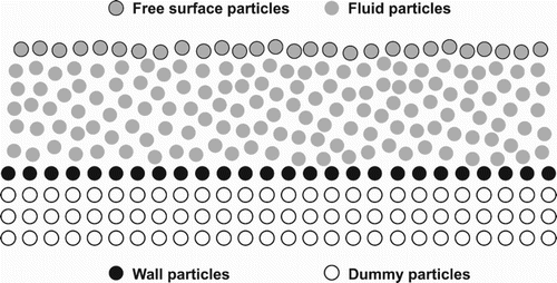
Close to the solid boundaries, such as the side walls and channel beds, the boundary conditions will influence the flows. As discussed previously, the particle number density decreases near the solid boundary, therefore dummy particles are generated outside the solid boundaries to compensate for the particle deficiency. These dummy particles ensure the correct neighbor search near the solid boundary and contribute to the computation of the properties for the fluid particles near the boundary. However, the dummy particles do not move and remain in their preset locations throughout the simulation. Several layers of dummy particles are defined according to the neighbor search radius, with the number of layers is usually set as the same as the neighbor search radius. The neighbor search radius re = 3Δl is used in the present study and therefore three layers of dummy particles are required outside the solid boundary. It should be noted that the pressure of the first layer of dummy particles is computed and then copied to the remaining two layers of dummy particles.
Practical boundary effects can be reflected by employing the dummy particles and assigning the corresponding properties to the dummy particles, such as the commonly used free-slip and no-slip boundary conditions.
2.5.2. Free surface boundary
Similar to the solid boundary, there is no particle outside the free surface boundary. However, the free surface boundary cannot be treated the same as the solid boundary. In MPS, the free surface particles are recognized by a critical particle number density defined as a certain percentage of the initial particle number density. The model is controlled to calculate the particle number density at every time step of the simulation for every particle movement, and the critical particle number density is defined as
(15) where β is the threshold coefficient. Obviously, β ranges between 0 and 1. In general, the value of β is between 0.8 and 0.99 (Koshizuka, Nobe, & Oka, Citation1998), and in the current study, β = 0.96 is used. shows the typical setup of the fluid particles, free surface particles, and solid boundary particles. As previously stated, wall particles are the first layer of dummy particles in .
3. Rheology model
Most non-Newtonian fluids show abrupt transformations in flow regimes over a relatively narrow range of the stress they undergo. In other words, these fluids will not show liquid-like behaviors when the stresses are not large enough (i.e., to generate continued deformations). In short, the viscosity of non-Newtonian fluids is shear rate dependent.
Those non-Newtonian fluids that exhibit a decreased viscosity with increasing shear rate are defined as shear-thinning fluids, which account for the majority of non-Newtonian fluid flows. The behaviors of shear-thinning materials have drawn attention over the last few decades due to their common presence in everyday activities and industries (Barnes, Citation1999). The flows of shear-thinning fluids are usually referred to as pseudoplastic flows.
To study the relationship between deformation and stress, rheology equations are commonly used. In the current WC-MPS study, the Cross rheology equation is used to investigate the non-Newtonian behaviors. In theory, an ideal rheology equation to relate viscosity and shear rate should provide an accurate fit for most experimental measurements over a wide range of the shear rate change (Cross, Citation1965). Moreover, the equation should include a minimum number of independent constants as well, since these constants will have real physical meaning and must be firmly evaluated accordingly. At least four parameters are required to predict the general flow behaviors of non-Newtonian fluids.
3.1. Cross equation
The Cross rheology equation (Cross, Citation1965) for non-Newtonian fluids was developed based on the assumption that the pseudoplastic flow is related to the formation and rupture of structural linkages of the materials:
(16) where γ is the shear rate, μ0 is the viscosity when the shear rate is close to zero, μ∞ is the viscosity when the shear rate is infinity, n is the flow behavior index, and α is the consistency index with the dimension of sn. For shear-thinning materials, the value of n is between 0 and 1.
Under the Bingham model (Shao & Lo, Citation2003), the fluid at rest can resist the shear stress less than yield stress without deformation. If the shear stress exceeds the yield stress, the fluid starts to flow and behaves as a Newtonian fluid. With the condition of αγn >> 1, n = 1, and using Bingham's theory to acquire the relationship of μ∞ = μB, τB = μ0/K, Shao and Lo (Citation2003) obtained a simplified Cross equation as:
(17) where μ0 = 1000μ∞, K can be determined by their method and μ∞ can be experimentally measured according to Bingham's theory. By certain approximations of the Cross equation, several other popular and rheology models can be obtained, such as the power law model, the Sisko model, and the Bingham's model (Barnes, Hutton, & Walters, Citation1989). However, to implement the Cross equation, the above-mentioned parameters need to be pre-determined before the implementation of the equation. In the current study, an experimental method is proposed to determine these parameters.
3.2. Parameter determination for the Cross equation
As indicated by Cross (Citation1965), the flow behavior index n needs to be determined first. The following section introduces a hybrid method with four steps to determine the four required parameters in the Cross equation. To demonstrate the proposed method for determining the parameters for the Cross equation, water-kaolinite mixtures with a solid volume concentration of 20% are used.
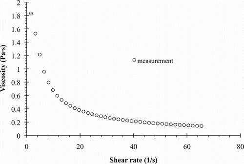
To determine the four parameters, a measured viscosity and shear rate relationship () is required, which can be usually measured using rheometers. A shear stress and shear rate relationship can also be measured by the rheometers and used to check the accuracy of the parameter estimates.
The first step is to determine the flow behavior index n, which is determined at first by a variation of the graphical method proposed by Cross (Citation1965). At a high shear rate αγn >> 1, therefore the Cross equation can be reduced to:
(18)
Converting Equation (18) into logarithmic form, the following relationship can be obtained:
(19)
Since μ∞ is the viscosity at a very high shear rate, it is extremely small compared to the effective viscosity. The material property changes dramatically; hence, the relationship of μ >> μ∞ can be used, and μ∞ on the left-hand side of Equation (19) can be ignored:
(20)
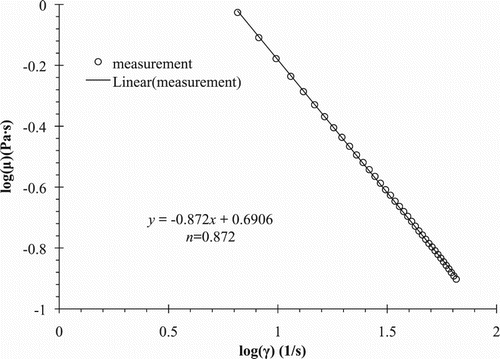
Then, the relationship between log μ and log γ can be drawn from the measurement. It should be noted that log μ is linear with log γ (), and n can be obtained as the slope of the linear relationship of log (u) and log (γ).
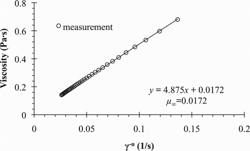
The second step is to determine the viscosity at the very high shear rate μ∞ by the graphical method. After the flow behavior index n is determined, μ∞ can then be determined. Converting Equation (16) into the form
(21) it can be seen that the relationship between μ and γ−n is linear with the interception of μ∞, as shown in . Therefore, μ∞ can be determined ().
Figure 4. Linear relationship between μ and γ-n to determine the viscosity at the very high shear rate μ∞.
The third step is to determine the viscosity at the very low shear rate μ0 by the relationship of μ0 = 1000μ∞. Owing to the findings of Hammad and Vradis (Citation1994) that μ0 has nearly no effect on the numerical accuracy when μ0 is 1000 times greater than μ∞, a fixed value of μ0 = 1000μ∞ is selected and used.
The fourth step is to determine the consistency index α by regressing fitting according to the Cross equation using the values of μ0, μ∞, and n from steps 1 to 3. The unique value of α can be obtained as the best-fitting curve with the measurement.
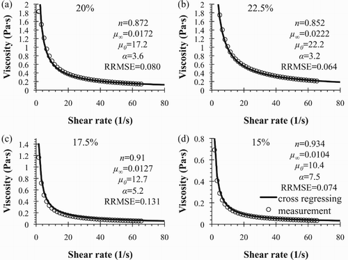
The final obtained values for the four parameters of the water-kaolinite mixtures with solid volume concentration Cv of 20% are shown in (a), along with the values for Cv = 22.5%, Cv = 17.5%, and Cv = 15%. From , it can be seen that the viscosity and shear rate relationship using the estimated parameters is in reasonably agreement with the experimental results. In (c), the Cross fittings have slight discrepancies between the shear rate range of 0 1/s and 15 1/s. Though the method to determine the parameters is based on the viscosity and shear rate relationships at high shear rate regions, the estimated parameters are nonetheless sufficiently accurate in depicting the non-Newtonian dam break flows, as indicated in the next section.
4. Applications
In order to validate the proposed method for determining the parameters for the Cross equation and its performance in the WC-MPS model, three different groups of dam break tests with different materials are used.
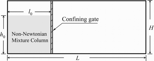
shows a sketch of the dam break test simulated in the current study. The initial channel length L, initial channel height H, initial mixture column length l0, and initial mixture column height h0 vary for different groups of tests; the channel width varies as well, but it is not considered here since the simulations are 2D. Water-kaolinite mixtures with a solid volume concentration of 25% were used for the first group of simulations (Xie, Tai, & Jin, Citation2013), water-clay mixtures (Komatina & Jovanovic, Citation1997) with different solid volume concentrations were used for the second group, and Carbopol 940 aqueous solutions with different Carbopol volume concentrations (Minussi & Maciel, Citation2012) were used for the last group.
4.1. Water-kaolinite mixtures of 25% solid volume concentration
The first group of experiments was carried out in a horizontal channel made of transparent Plexiglas of 1392 mm length, 51 mm width, and 200 mm depth. A high-speed CMOS camera was used to capture the flow movement. The camera was located 1.5 m away from the channel. The initial water-kaolinite column was set as 356 mm long and 100 mm high.
For the numerical simulations, 8900 fluid particles were used with a total number of 11,014 particles including the dummy particles. The particle size (or the initial particle distance) was set as 0.002 m. Before the dam break flow was initiated, all the particles were distributed evenly and the hydrostatic pressure conditions were assigned to the particles.
According to the experimental measurements, the time span for the removal of the confining gate was 0.1 s. The movement of the confining gate was considered during the simulation. The speed of removing the gate was assumed to be constant as 1 m/s, and consequently the gate was fully removed 0.1 s after the simulation was initiated.
(a) shows the estimated Cross parameters and the corresponding shear stress and shear rate relationships for the 25% water-kaolinite mixture. From (a) it can be seen that the viscosity and shear rate relationship using the estimated Cross parameters agree well with the measurements, with a slight underestimation of the viscosity at low shear rates. Moreover, (b) shows the comparison of the shear stress and shear rate relationship between the estimated value and the measurements. The underestimation of the shear stress at lower shear rates is due to the underestimated viscosities, which further confirms the current method for determining the four parameters for the Cross equation. These estimated parameters are then used in the following simulation of the dam break flow of the 25% water-kaolinite mixture.
Figure 7. The relationship between (a) the viscosity and the shear rate and (b) the shear stress and the shear rate for water-kaolinite mixture at Cv = 25%.
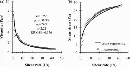
The relative root mean square error (RRMSE) between the calculated viscosity using the proposed method and the measured ones is shown in Figures and . The small RRMSE values indicate good agreement between the calculated viscosities and the experimental measurements. However, as shown in (a), when the shear rate is less than 5 1/s, the measured values of viscosities in this shear rate range are not stable. This may be because the more viscous nature of the mixture at higher solid volume concentrations leads to difficulties in accurately measuring the viscosities at lower shear rates (0 1/s to 5 1/s).
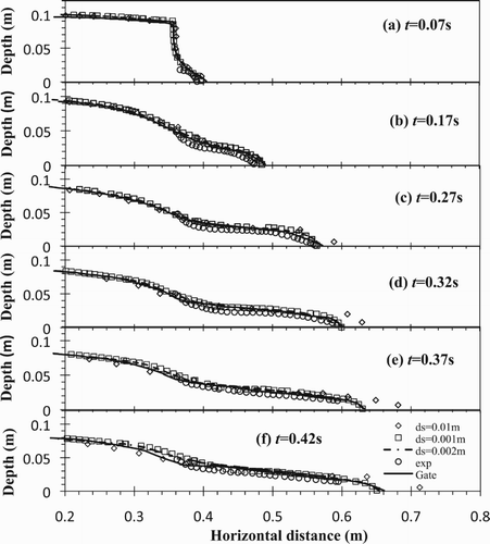
indicates the flow regimes of both the laboratory measurements and the WC-MPS simulations for the water-kaolinite mixtures at a concentration of 25%. The simulations show reasonable agreement with the experiments. It can been seen from that, due to the more viscous nature of the water-kaolinite mixture which is different from the water dam break, the dam break of the water-kaolinite mixture has its flow depth and front propagating velocity decaying more rapidly over time. This important flow feature of a typical non-Newtonian dam break flow was observed in the simulations as well.
More specifically, since the confining gate was considered to be removed at a constant speed of 1 m/s and was opened completely at 0.1 s following the simulation initiation, the flow pattern was considerably affected before 0.1 s. There is a relatively slow fracturing avalanche of the initial reservoir heaps due to the partially opened confining gate before 0.1 s ((a)), which transits to more violent cascading collapses of the taller part of the material column ((b)). At 0.17 s after the complete gate removal, a rapid drop of the flow depth due to the influence of gravity was observed near the leading edge of the mixture column. The flow depth reduced to approximately 50 mm (half of the initial column height) at x = 0.356 m, after which the flow depths were almost fixed at around 50 mm with very little fluctuation. The numerical simulations of WC-MPS have shown this feature clearly during the flow ().
On the other hand, at the beginning of the flow, right after the initial hydrostatic state ((a)), the numerical simulation shows discrepancies with the experimental measurements. This is largely attributed to the high viscosity of the 25% water-kaolinite mixture. More specifically, owing to the highly viscous nature of the mixture and the high viscosity, the mixture will exhibit a more solid-like behavior due to being attached to the confining gate and moving upwards with the gate for a short distance. Since the gate removal in the experiments is not instantaneous, the dam break is modeled by removing gate particles with a constant speed of 1 m/s in the simulation process. The gate opening was also simulated by assigning no-slip boundary conditions to the gate modeling process. There are some improvements with no-slip boundary condition, as shown in the simulation results. Fu and Jin (Citation2014) studied the effect of using a smaller particle size in their dam break cases. They indicated that by using a smaller particle size, a more accurate simulation was obtained but with the downside of requiring an extremely time-consuming calculation. As shown in , the simulated water surface profiles are similar for the particle sizes ds = 0.002 m and ds = 0.001 m, even though the total number of fluid particles are four times less and the simulation time is at least eight times less.
A small overestimation of the flow depths was observed in the simulations. As mentioned above, due to the highly viscous nature of the mixture and the corresponding high viscosity, the mixture is more difficult to propel as it sticks to the gate, so the amount of material mass passing through the gate decreases during the removal of the confining gate, leading to the slightly overestimated flow depths.
4.2. Water-clay mixtures
Komatina and Jovanovic (Citation1997) conducted experiments with water-clay mixtures of dam break flow that included 69 tests with different clay volume concentrations ranging between 0.0% and 36.1% for the initial reservoir height from 100 mm to 300 mm and channel slopes of 0.0% and 0.1%. Three cases, with an initial reservoir height of 100 mm, a channel slope of 0.1%, and clay volume concentrations of 13.9%, 20.1%, and 27.4%, respectively, were selected from their work for the numerical investigations in the current study. illustrates the variation of the properties of the water-clay mixture with the clay volume concentration.
Table 1. Physical properties of the water-clay mixtures.
In the numerical simulations, a total of 59,632 particles 0.002 m in size were constructed, including 50,000 fluid particles. All particles were uniformly distributed initially and the hydrostatic pressure condition was assigned. As with the same treatment in the previous section, a moveable confining gate was set during the simulation and the gate was assumed to move upwards completely within 0.1 s when simulation was initiated.
shows the parameters estimated for the Cross equation by the method proposed in this study for the water-clay mixtures, and shows the calculated shear stress; the shear rate relationships with the viscosities computed from the Cross equation in comparison to the Bingham theory are shown as well. The Bingham model curve in refers to Komatina and Jovanovic's (Citation1997) findings for water-clay mixtures, which state that Bingham's model can be used to study the behaviors of the mixtures by neglecting the non-linearity of the viscosity at low shear rates. However, the non-linearity of the viscosity at low shear rates will affect the flow features of the mixtures at the beginning of the flows, as the viscosity changes dramatically during the early stage of the flows. This is the reason the Cross equation is used to perform the numerical tests for the dam break flow of the water-clay mixtures in the current study, since the dam break flows usually occur over a very short timescale and in the narrow shear rate region, during which the viscosity of the material decreases sharply. It can be seen from that the calculated relationships using Cross equations are in good agreement with the experimental results. The zoomed plots at the right-hand side of each plot show the comparisons at lower shear rates from 0 1/s to 10 1/s. It is obvious that at the lower shear rate, the Cross theory provides a non-linear relationship between the shear stress and the shear rate rather than the fixed value of the Bingham theory.
Figure 9. Shear stress and shear rate relationships for the water-clay mixtures for different values of Cv.
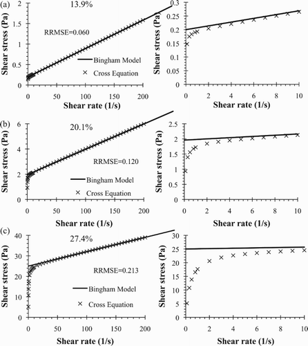
Table 2. Estimated Cross parameters for the water-clay mixtures.
also shows the RRMSE values between the calculated shear stress from the proposed method and the calculations from Bingham's equation with the estimated Bingham parameters from experiments (Komatina & Jovanovic, Citation1997). The small RRMSE values also show good agreement between the calculated shear stress and the shear stress from Bingham's equation.
However, there are discrepancies between the two curves in at a very low shear rate (<5 1/s), and these discrepancies contribute to the increased RRMSE values even when the RRMSE is small. These discrepancies are due to the different descriptions of flows at a very low shear rate. Bingham's model can be considered as a simplified form of the Cross equation (Barnes et al., Citation1989), while Bingham's rheology law assumes no movement below the yield stress even when the material is undergoing small shears. Therefore, when a material is experiencing smaller shears than the Bingham's yield stresses, the actual deformation or movement cannot be reflected by using Bingham's model. As such, Bingham's law may not accurately describe the flow features at a very low shear rate. It is worth noting that the discrepancies become smaller as the shear rate increases ((a) to (c)), indicating that both the Cross equation and Bingham's equation are comparable at higher shear rates.
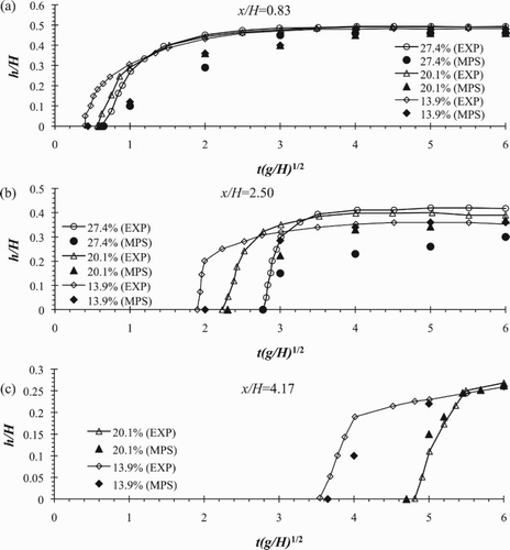
The front depths at different cross-sections, namely, the stage hydrographs, are shown in . It is clear that the MPS simulations take a longer time to reach the same flow depth of the measurements in all three cross-sections. The major reason for this latency is the particles reaching the cross-sections.
In (a), x/H = 0.83 refers to the cross-section immediately after the initial dam site. The MPS simulation of the flow depth at this depth reaches the same value as the measurement at around 0.4 s for all concentrations, while further away from the initial dam site ((b)), x/H = 2.50, the MPS simulations take 0.6 s to reach the measured depths for all concentrations. However, with a lower concentration, the simulation results of the flow depth take less time to reach the measured depths due to the larger viscosities of the higher concentrations and the existence of the confining gate; fluid of a higher viscosity is more prone to sticking to the gate in the real flows, causing a delay at the initiation of the flow – but this delay not included in the current MPS model.
At the furthest distance measured from the initial dam site ((c)), x/H = 4.17, no flow reaches the location for the concentration 27.4% due to the slower movement caused by the high viscosity of the mixture. The MPS simulation shows better agreement here than with the previous two cross-sections.
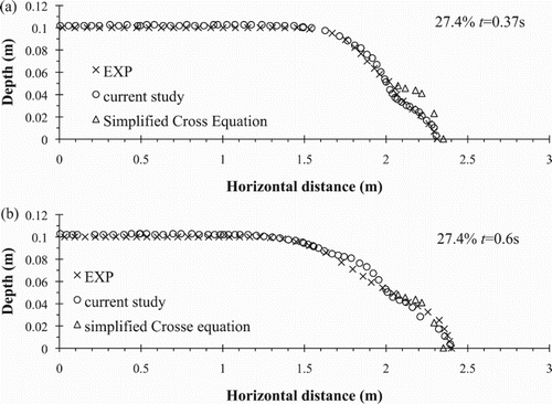
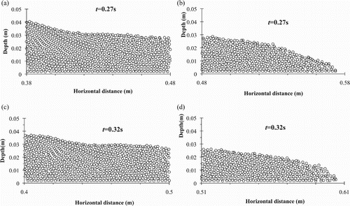
shows the surface comparisons between the simulations using the method proposed and the experiments at different times, and the simulation results of the simplified Cross equation with WC-MPS (Xie et al., Citation2013) are shown as well. It is clear that the surface profiles of the current simulations are in good agreement with the experimental results. This is the advantage of the particle method in tracking free surfaces. In (b), slight discrepancies are observed between x = 1.6 m and x = 2 m in the MPS simulations compared with the experiments. It is suspected that this is due to the local particles at these locations, as the weakly compressible nature of the current MPS model is for weakly compressible fluid that may lead to particles clustering at these locations. In the current model, particle clustering is avoided by using repulsive force in the pressure calculation (Koshizuka et al., Citation1998). Snapshots of the WC-MPS results at t = 0.27 s and t = 0.32 s for 25% simulation are shown in . It can been seen that there are a few particles which slightly overlap with each other, but a more reasonable overall distribution of the fluid particle is obtained due to the existence of the repulsive forces.
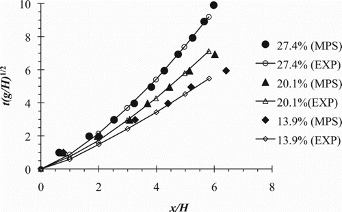
In order to further study the capabilities of the MPS method for simulating non-Newtonian flows with different concentrations, the wave front propagation was compared for different concentrations. Good agreement was found between the simulations and measurements (). The speed of the wave front propagation decreases as the mixture concentration increases, and this viscous flow feature can be seen in as well. This also confirms the validity of the method proposed in the current study in determining the parameters for the Cross equation and the ability of the current WC-MPS model with the Cross equation in simulating non-Newtonian fluid flows.
4.3. Carbopol 940 aqueous solutions
The last group of experiments selected in this study is the work of Minussi and Maciel (Citation2012). In their experimental study, rheological tests were performed for Carbopol 940 aqueous solutions of five different concentrations. Among the experimental studies, three groups of dam break tests were performed with different initial reservoir heights h0. Two initial reservoir heights, h0 = 100 mm and h0 = 130 mm, were selected in the current study to validate the numerical model. gives the details of the selected experiments. The density of the Carbopol 940 solutions was selected as 1007 kg/m3 as suggested by Minussi and Maciel (Citation2012) and kept the same for all five fluids, since the concentration variations of the five fluids are small.
Table 3. Setup of the Carbopol 940 dam break tests.
lists the properties of the five Carbopol 940 aqueous solutions for different concentrations.
Table 4. Properties of the Carbopol 940 solutions and the corresponding rheological parameters for the Herchel–Bulkley model.
During the numerical simulations, the particle size for both groups was set as 0.002 m. There were 12,500 fluid particles and a total of 16,954 particles (including dummy particles) for the tests in Group 1 and 16,250 fluid particles and a total of 20,704 particles for the tests in Group 2. All particles were uniformly distributed initially and the hydrostatic pressure condition was assigned to the particles.
shows the comparisons between the Cross equation using the fitted parameters and the calculation by the Herchel–Bulkley model with the estimated parameters (Minussi & Maciel, Citation2012). The RRMSE values are shown as well and indicate reasonable agreement between the calculated viscosities and the viscosities from Minussi and Maciel (Citation2012). There are discrepancies between the calculated viscosities and the viscosities from Minussi and Maciel (Citation2012) at the shear rate range of 10 1/s and 50 1/s. Since the Cross equation and the Herchel–Bulkley model provide different descriptions at a low shear rate, the discrepancies for these two rheology laws become smaller as the shear rate increases.
Figure 14. The relationship between the viscosity and the shear rate for the Carbopol 940 aqueous solutions with different constituents.
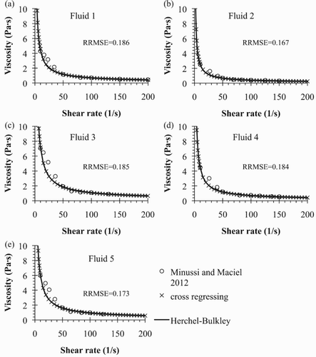
Therefore, as shown in the figures, the relationships estimated from the proposed method show reasonable agreement with the apparent viscosity obtained by Minussi and Maciel (Citation2012), with slight underestimations of the viscosity between the shear rate of 25 1/s and 50 1/s. On the other hand, the estimated relationship shows good agreement with the Herchel–Bulkley model, confirming the validity of the method in describing the rheological properties for non-Newtonian materials.
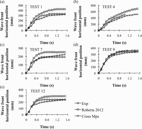
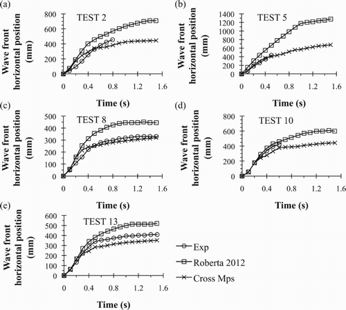
shows the estimated Cross parameters for the Carbopol 940 aqueous solutions using the proposed method, and Figures and illustrate wave front comparisons between the WC-MPS results and the experiments of Minussi and Maciel (Citation2012) for Group 1 and Group 2, respectively. The numerical results of Minussi and Maciel (Citation2012) using ANSYS CFX software are shown as well.
Table 5. Estimated Cross parameters for the Carbopol 940 solutions.
For both of the test groups (100 mm and 130 mm initial mixture height for Group 1 and Group 2, respectively), the WC-MPS simulations underestimated the wave front locations compared with the measurements. The major reason for this is the errors that are introduced in the parameter fitting process for the Cross equation and the errors induced by the use of the Cross equation, since the Cross equation itself is a constitutive equation derived based on the assumption of the pseudoplastic flow of non-Newtonian materials in connection with the formation and rupture of structural linkages.
From Figures and , it can be seen that the current simulations show overestimations of the wave front locations at the early stage of the flows for several tests, i.e., test 1 ((a)), test 2 ((a)), test 4 ((b)), test 7 ((c)), and test 8 ((c). By analyzing the relationships of the materials in , the µ0 (viscosity at a very low shear rate) from the Cross fitting is larger than the apparent viscosity, and the estimated viscosity decreases sharply with the increase of the shear rate ranging through 0 1/s to 50 1/s. Then, the estimated viscosity agrees well with the apparent viscosity. Since the WC-MPS method adopts the estimations of the Cross equation and the higher µ0, the material is slower to initiate flow at lower shear rates (i.e., at the beginning of the collapse). Thus, the sharp decrease in viscosity with the shear rate indicates that the material has a lower viscosity under the same shear rate compared with the experimental results. Subsequently, the lower viscosity induces a larger front propagating velocity and, added to the absence of the confining gate in the simulations, this finally leads to the overestimation of the wave front locations. In addition, the discrepancy between the numerical and experimental results may due to the application of the WC-MPS method, and modifications such as using an enhanced MPS technique (Khayyer & Gotoh, Citation2013) may improve the fit between the numerical and experimental results.
Nonetheless, the model still underestimated the wave front locations. From the relationship between the viscosity and the shear rate fitted from the Cross equation, the viscosity drops sharply at first and then maintains a smooth and steady decrease over the shear rate change between 0 1/s and 50 1/s, which indicates that the model overestimates the propagating velocity at first, and then the velocity decreases at a very slow pace while the apparent viscosity drops dramatically within the same shear rate range, and this sharp decrease in viscosity, at last, leads to a faster increase in propagating velocity than the model predicts. Consequently, the model has an underestimated velocity and thus underestimates the wave front locations.
5. Conclusion
In this study, the WC-MPS model was used to study the free surface flow of non-Newtonian fluid. The flow development process and regimes are directly represented by particle interactions and movements. The non-Newtonian nature and flow behaviors are accounted for by the Cross rheology equation coupled with an experiment-based method to estimate the parameters required by the Cross equation. The viscosity and the shear rate relationships obtained from the Cross equation and the proposed parameter-determination method were compared with the experimental measurements for three different sets of tests with different non-Newtonian materials. Good agreement was found between the proposed method and the measurements. The estimated parameters together with the Cross equation were then applied within the WC-MPS model to numerically study the dam break flows of the materials. The surface profiles and wave front locations of the simulations are in good agreement with the experimental results, indicating that the proposed method to estimate the Cross parameters and the use of the Cross equation can capture the flow regimes of non-Newtonian materials, as well as showing the capability of the weakly compressible particle method to simulate non-Newtonian free surface flows.
However, the current WC-MPS model has several limitations. Comparisons of the stage hydrographs of the water-clay mixtures show that in order to accurately track the front depth of the flows, more particles with decreased particle sizes are required, which will increase the computation cost. A more advanced computing method and technology to accompany it will greatly improve the efficiency when large amounts of particles are employed. On the other hand, a more sophisticated interaction model is absent from the current model to further improve the accuracy, including the physical mechanisms between the fluid and the confining gate, as well as the interaction between the non-Newtonian material and the solid boundaries. The current model is limited to 2D simulations, thus a 3D model considering the effects of the lateral directions along the channel width will improve the applicability of the WC-MPS method to more practical engineering problems with non-Newtonian materials.
Nonetheless, due to the advantage of the WC-MPS method in handling flows with large deformation and fragmentation, and its capability of treating different types of fluid flows, the WC-MPS method can be expanded to study more practical problems, such as sophisticated 3D flows (C. L. Wu & Chau, Citation2006), salinity and temperature (Chau & Jiang, Citation2001, Citation2004), and multiphase flow problems (T. Liu & Yang, Citation2014). Moreover, using the MPS method to solve the shallow water equation (SWE; Lai & Khan, Citation2012; Pu et al., Citation2013) also hold great promise in improving the devising of solutions for practical problems as well.
Acknowledgements
The authors would like to thank Dr Y. C. Tai and Mr Bo-Jun Chen for providing experimental data.
Disclosure statement
No potential conflict of interest was reported by the authors.
Additional information
Funding
References
- Ataie-Ashtiani, B., & Farhadi, L. (2006). A stable moving-particle semi-implicit method for free surface flows. Fluid Dynamics Research, 38(4), 241–256. doi: 10.1016/j.fluiddyn.2005.12.002
- Barnes, H. A. (1999). The yield stress—a review or ‘παντα ροι‘—everything flows? Journal of Non-Newtonian Fluid Mechanics, 81, 133–178. doi: 10.1016/S0377-0257(98)00094-9
- Barnes, H. A., Hutton, J. F., & Walters, K. (1989). An introduction to rheology. Amsterdam: Elsevier Science.
- Basu, D., Das, K., Jenetzke, R., & Green, S. (2011). Numerical simulations of non-Newtonian geophysical flows using smoothed particle hydrodynamics (SPH) method: A rheological analysis. ASME 2011 International Mechanical Engineering Congress and Exposition: 155–164.
- Chau, K. W., & Jiang, Y. W. (2001). 3D numerical model for Pearl river estuary. ASCE Journal of Hydraulic Engineering, 127(1), 72–82. doi: 10.1061/(ASCE)0733-9429(2001)127:1(72)
- Chau, K. W., & Jiang, Y. W. (2004). A three-dimensional pollutant transport model in orthogonal curvilinear and sigma coordinate system for Pearl river estuary. International Journal of Environment and Pollution, 21(2), 188–198. doi: 10.1504/IJEP.2004.004185
- Chen, X., Xi, G., & Sun, Z. (2014). Improving stability of MPS method by a computational scheme based on conceptual particles. Computational Methods in Applied Mechanics and Engineering, 278, 254–271. doi: 10.1016/j.cma.2014.05.023
- Crespo, A. J. C. (2008). Application of the smoothed particle hydrodynamics model SPHysics to free-surface hydrodynamics. (PhD thesis), University of Vigo, Vigo, Galicia, Spain.
- Cross, M. M. (1965). Rheoogy of non-Newtonian fluids: A new flow equation for pseudoplastic systems. Journal of Colloid Science, 20(5), 417–437. doi: 10.1016/0095-8522(65)90022-X
- Dalrymple, R. A., & Roger, B. D. (2006). Numerical modeling of water waves with the SPH method. Coastal Engineering. Coastal Hydrodynamics and Morphodynamics, 53(2–3), 141–147.
- Fan, X., Tanner, R., & Zhang, R. (2010). Smoothed particle hydrodynamics simulation of non-Newtonian moulding flow. Journal of Non-Newtonian Fluid Mechanics, 165(5–6), 219–226. doi: 10.1016/j.jnnfm.2009.12.004
- Fu, L., & Jin, Y. C. (2014). Simulating velocity distribution of dam breaks with the particle method. ASCE Journal of Hydraulic Engineering, 140(10), 04014048. doi: 10.1061/(ASCE)HY.1943-7900.0000915
- Gotoh, H., Ikari, H., Memita, T., & Sakai, T. (2005). Lagrangian particle method for simulation of wave overtopping on a vertical seawall. Coastal Engineering Journal, 47(2–3), 157–181. doi: 10.1142/S0578563405001239
- Gotoh, H., & Sakai, T. (2006). Key issues in the particle method for computation of wave breaking. Coastal Engineering, 53(2–3), 171–179. doi: 10.1016/j.coastaleng.2005.10.007
- Gotoh, H., Shibahara, T., & Sakai, T. (2001). Sub-particle-scale turbulence model for the MPS method- Lagrangian flow model for hydraulic engineering. Computational Fluid Dynamics Journal, 9(4), 339–347.
- Hammad, K. J., & Vradis, G. C. (1994). Flow of a non-Newtonian Bingham plastic through an axisymmetric sudden contraction: Effects of Reynolds and yield numbers. Numerical Methods in Non-Newtonian Fluid Dynamics, ASME FED, 179, 63–70.
- Heo, S., Koshizuka, S., & Oka, Y. (2002). Numerical analysis of boiling on high heat-flux and high subcooling condition using MPS-MAFL. International Journal of Heat and Mass Transfer, 45(13), 2633–2642. doi: 10.1016/S0017-9310(02)00011-X
- Khayyer, A., & Gotoh, H. (2008). Development of CMPS method for accurate water surface tracking in breaking wave. Coastal Engineering Journal, 50(2), 179–207. doi: 10.1142/S0578563408001788
- Khayyer, A., & Gotoh, H. (2013). Enhancement of performance and stability of MPS mesh-free particle method for multiphase flows characterized by high density ratios. Journal of Computational Physics 2013, 242, 211–233.
- Komatina, D., & Jovanovic, M. (1997). Experimental study of steady and unsteady free surface flows with water-clay mixtures. Journal of Hydraulic Research, 35(5), 579–590. doi: 10.1080/00221689709498395
- Koshizuka, S., Nobe, A., & Oka, Y. (1998). Numerical analysis of breaking waves using the moving particle semi-implicit method. International Journal for Numerical Methods in Fluid, 26, 751–769. doi: 10.1002/(SICI)1097-0363(19980415)26:7<751::AID-FLD671>3.0.CO;2-C
- Koshizuka, S., & Oka, Y. (2001). Application of moving particle semi-implicit method to nuclear reactor safety. Computational Fluid Dynamics Journal, 9, 366–375.
- Koshizuka, S., Tamako, H., & Oka, Y. (1995). A particle method for incompressible viscous flow with fluid fragmentation. Computational Fluid Dynamics Journal, 4(1), 29–46.
- Lai, W., & Khan, A. A. (2012). Discontinuous Galerkin method for 1D shallow water flows in natural rivers. Engineering Applications of Computational Fluid Mechanics, 6(1), 74–86. doi: 10.1080/19942060.2012.11015404
- Li, D., Sun, Z., Chen, X., Xi, G., & Liu, L. (2015). Analysis of wall boundary in moving particle semi-implicit method and a novel model of fluid–wall interaction. International Journal of Computational Fluid Dynamics, 29(3–5), 199–214. doi: 10.1080/10618562.2015.1028924
- Liu, J., Koshizuka, S., & Oka, Y. (2005). A hybrid particle-mesh method for viscous, incompressible, multiphase flows. Journal of Computational Physics, 202(1), 65–93. doi: 10.1016/j.jcp.2004.07.002
- Liu, T., & Yang, J. (2014). Three-dimensional computations of water-air flow in a bottom spillway during gate opening. Engineering Applications of Computational Fluid Mechanics, 8(1), 104–115. doi: 10.1080/19942060.2014.11015501
- Lube, G., Herbert, E. H., Sparks, R. S. J., & Freundt, A. (2011). Granular column collapses down rough, inclined channels. Journal of Fluid Mechanics, 675, 347–368. doi: 10.1017/jfm.2011.21
- Major, J. J., & Pierson, T. C. (2010). Debris flow rheology: Experimental analysis of fine-grained slurries. Water Resources Research, 28(3), 841–857. doi: 10.1029/91WR02834
- Martys, N. S., George, W. L., Chun, B. W., & Lootens, D. (2010). A smoothed particle hydrodynamics-based fluid model with a spatially dependent viscosity: Application to flow of a suspension with a non-Newtonian fluid matrix. Rheollogica Acta Acta, 49, 1059–1069. doi: 10.1007/s00397-010-0480-7
- Minussi, R. B., & Maciel, dF. M. (2012). Numerical experimental comparison of dam break flows with non-Newtonian fluids. Journal of the Brazilian Society of Mechanical Sciences and Engineering, 34(2), 167–178. doi: 10.1590/S1678-58782012000200008
- Narayanaswamy, M. S. (2008). A hybrid Boussinesq-SPH wave propagation model with applications to forced waves inrectangular tanks. (PhD thesis), Johns Hopkins University, Baltimore, Maryland, U.S.
- Pan, W., Tartakovsky, A. M., & Monaghan, J. J. (2013). Smoothed particle hydrodynamics non-Newtonian model for ice-sheet and ice-shelf dynamics. Journal of Computational Physics, 242, 828–842. doi: 10.1016/j.jcp.2012.10.027
- Pu, H. J., Shao, S. D., Huang, Y. F., & Hussain, K. (2013). Evaluations of SWEs and SPH numerical modelling techniques for dam break flows. Engineering Applications of Computational Fluid Mechanics, 7(4), 544–563. doi: 10.1080/19942060.2013.11015492
- Riviere, S., Khelladi, S., Farzaneh, S., Bakir, F., & Tcharkhtchi, A. (2013). Simulation of polymer flow using smoothed particle hydrodynamics method. Polymer Engineering and Science, 53(12), 2509–2518. doi: 10.1002/pen.23512
- Roche, O., Montserrat, S., Nino, Y., & Tamburrino, A. (2008). Experimental observations of water-like behavior of initially fluidized, dam break granular flows and their relevance for the propagation of ash-rich pyroclastic flows. Journal of Geophysical Research: Solid Earth, 113(B12), 1–15. doi: 10.1029/2008JB005664
- Shakibaeinia, A., & Jin, Y. C. (2010). A weakly compressible MPS method for modeling of open boundary free-surface flow. International Journal for Numerical Methods in Fluids, 63(10), 1208–1232.
- Shao, S. D., & Lo, Y. M. (2003). Incompressible SPH method for simulating Newtonian and non-Newtonian flows with a free surface. Advances in Water Resources, 26, 787–800. doi: 10.1016/S0309-1708(03)00030-7
- Shibata, K., & Koshizuka, S. (2007). Numerical analysis of shipping water impact on a deck using a particle method. Ocean Engineering, 34, 585–593. doi: 10.1016/j.oceaneng.2005.12.012
- Spinewine, B., & Capart, H. (2013). Intense bed-load due to a sudden dam-break. Journal of Fluid Mechanics, 731, 579–614. doi: 10.1017/jfm.2013.227
- Sueyoshi, M., Kashiwagi, M., & Naito, S. (2008). Numerical simulation of wave-induced nonlinear motions of a two-dimensional floating body by the moving particle semi-implicit method. Journal of Marine Science and Technology, 13, 85–94. doi: 10.1007/s00773-007-0260-y
- Sun, H., & Han, J. (2010). A particle-based unified model for non-Newtonian fluid simulation. Second International Conference on Computer Modeling and Simulation, 290–294.
- Sun, Z., Xi, G., & Chen, X. (2009). A numerical study of stir mixing of liquids with particle method. Chemical Engineering Science, 64, 341–350. doi: 10.1016/j.ces.2008.10.034
- Tao, J., Ren, J. L., Lei, X., & Lu, L. G. (2014). A corrected smoothed particle hydrodynamics approach to solve the non-isothermal non-Newtonian viscous fluid flow problems. Acta Physica Sinica, 63(21), 210203.
- Tsubota, K., Wada, S., Kamada, H., Kitagawa, Y., Lima, R., & Yamaguchi, T. (2006). A particle method for blood flow simulation – application to flowing red blood cells and platelets. Journal of the Earth Simulator, 5, 2–7.
- Wang, X. B., Morgenstern, N. R., & Chan, D. H. (2010). A model for geotechnical analysis of flow slides and debris flows. Canadian Geotechnical Journal, 47(12), 1401–1414. doi: 10.1139/T10-039
- Whipple, K. X. (1997). Open-channel flow of Bingham fluids: Applications in debris-flow research. The Journal of Geology, 105(2), 243–262. doi: 10.1086/515916
- Wu, C. L., & Chau, K. W. (2006). Mathematical model of water quality rehabilitation with rainwater utilization — a case study at Haigang. International Journal of Environment and Pollution, 28(3–4), 534–545. doi: 10.1504/IJEP.2006.011227
- Wu, Q. R., Tan, M. Y., & Xing, J. T. (2014). An improved moving particle semi-implicit method for dam break simulation. Journal of Ship Mechanics, 18(9), 1044–1054.
- Xiang, H., & Chen, B. (2015). Simulating non-Newtonian flows with the moving particle semi-implicit method with an SPH kernel. Fluid Dynamics Research, 47, 015511. doi: 10.1088/0169-5983/47/1/015511
- Xie, J., Tai, Y. C., & Jin, Y. C. (2013). Study of the free surface flow of water-kaolinite mixture by moving particle semi-implicit (MPS) method. International Journal fro Numerical and Analytical Methods in Geomechanics, 38(8), 811–827. doi: 10.1002/nag.2234

