ABSTRACT
To reduce the total design and optimization time, numerical analysis with surrogate-based approaches is being used in turbomachinery optimization. In this work, multiple surrogates are coupled with an evolutionary genetic algorithm to find the Pareto optimal fronts (PoFs) of two centrifugal pumps with different specifications in order to enhance their performance. The two pumps were used a centrifugal pump commonly used in industry (Case I) and an electrical submersible pump used in the petroleum industry (Case II). The objectives are to enhance head and efficiency of the pumps at specific flow rates. Surrogates such as response surface approximation (RSA), Kriging (KRG), neural networks and weighted-average surrogates (WASs) were used to determine the PoFs. To obtain the objective functions’ values and to understand the flow physics, Reynolds-averaged Navier–Stokes equations were solved. It is found that the WAS performs better for both the objectives than any other individual surrogate. The best individual surrogates or the best predicted error sum of squares (PRESS) surrogate (BPS) obtained from cross-validation (CV) error estimations produced better PoFs but was still unable to compete with the WAS. The high CV error-producing surrogate produced the worst PoFs. The performance improvement in this study is due to the change in flow pattern in the passage of the impeller of the pumps.
Nomenclature
Abbreviations
| BPS | = | Best PRESS surrogate |
| CFD | = | Computational fluid dynamics |
| CV | = | Cross validation |
| ESP | = | Electrical submersible pump |
| KRG | = | Kriging |
| LE | = | Leading edge |
| NSGA-II | = | Non-dominated sorting of genetic algorithm-II |
| POD | = | Pareto optimal design |
| PoF | = | Pareto optimal front |
| PRESS | = | Predicted error sum of squares |
| RANS | = | Reynolds-averaged Navier–Stokes |
| RBF | = | Radial basis function |
| RMSE | = | Root mean square error |
| RSA | = | Response surface approximation |
| TE | = | Trailing edge |
| WAS | = | Weighted-average surrogate |
Greek Symbols
| Symbols | ||
| b | = | Blade width, mm |
| c | = | Absolute fluid flow velocity, m/s |
| d | = | Diameter, mm |
| Err | = | Error |
| F | = | Objective function |
| G | = | Blade number |
| H | = | Head, m |
| i, j | = | Integer value 1, 2, … |
| N | = | Number of models |
| n | = | Number of objectives |
| Q | = | Volume flow rate, m3/s |
| t | = | Blade thickness, mm |
| v | = | Absolute fluid flow velocity, m/s |
| w | = | Weighting function |
| x | = | Decision variable |
| β | = | Blade angle, ° |
| η | = | Hydraulic efficiency, % |
Subscripts
| 1 | = | Inlet |
| 2 | = | Outlet |
| avg | = | Average |
| CFD | = | Computational fluid dynamics |
| C | = | Combined |
| c | = | Absolute velocity, m/s |
| dv | = | Design variables |
| Err | = | Error |
| H | = | Head generated |
| krg | = | Kriging |
| o | = | Outer diameter of impeller |
| POD | = | Pareto optimal design |
| RANS | = | Reynolds-averaged Navier–Stokes |
| REF | = | Reference |
| rbf | = | Radial basis function |
| rsa | = | Response surface approximation |
| SM | = | Surrogate model |
| u | = | Peripheral component |
| η | = | Hydraulic efficiency |
1. Introduction
With the advancement of computational capabilities, the three-dimensional simulation of any complex geometries such as turbomachines is possible. Even an analysis of multistage pumps is possible, although a detailed analysis takes a long time. The optimization of a turbomachines requires a large amount of performance data at different design points in order to generate an objective function. This process may take a long time to simulate, and thus the cost of optimization can be high. Derakhshan, Pourmahdavi, Abdolahnejad, Reihani, and Ojaghi (Citation2013) reported an approach for enhancing the performance of turbomachines by optimizing its parameters via experimental and numerical methods. Hundreds of parameters of an impeller can be altered and the performance can be upgraded. The parameter such as number of blades affects the low-pressure area at the blade inlet and the jet wake formation in the blade passages (Houlin, Yong, Shouqi, Minggao, & Kai, Citation2010). A change in blade angles changes the hydraulic efficiency and the cavitation formation (Kamimoto & Matsuoka, Citation1956; Luo, Zhang, Peng, Xu, & Yu, Citation2008; Sanda & Daniela, Citation2012). Rutter, Sheth, and O'Bryan (Citation2013) optimized the hydraulic performance of an electrical submersible pump (ESP) handling a single-phase fluid, with selected head, efficiency and input power as the objective functions. Cao, Peng, and Yu (Citation2004), Shi, Long, Li, Leng, and Zou (Citation2010) and Marsis, Pirouzpanahand, and Morrison (Citation2013) also reported an improvement in pump performance by changing the design parameters.
However, the evaluation of all the parameters for optimization requires a high-dimensional analysis that is even more time consuming. To avoid this issue, a recently developed regression-based technique which generates a low-fidelity model also known as a surrogate is being used to assist engineers to optimize geometry in less time. The issue of the ‘dimensionality curse’ of surrogate models is usually helped by a sensitivity analysis, which can reduce the number of design parameters (Samad, Citation2008). Here, the low-fidelity model specifies an approximating function which approximately mimics the high-fidelity computational fluid dynamics (CFD) or computer aided engineering (CAE) model.
The surrogate models used for system optimization (also known as simply ‘surrogates’ or low-fidelity models) are highly dependent on the responses produced by the high-fidelity model (Forrester, Sobester, & Keane, Citation2008). If the wrong surrogate is selected for a low-fidelity construction then an erroneous result may be produced. There are many articles which investigate surrogate predictions and their comparative results (Acar & Rais-Rohani, Citation2009; Forrester & Keane, Citation2009; Goel, Haftka, Shyy, & Queipo, Citation2007; Lee & Choi, Citation2014; Nguyen, Reiterand, & Rigo, Citation2014; Peter & Onera, Citation2008; Robinson, Citation2007; Samad, Kim, Goel, Haftka, & Shyy, Citation2008; Sanchez, Pintos, & Queipo, Citation2008; Viana, Simpson, Balabanov, & Toropov, Citation2014; Zerpa, Queipo, Pintos, & Salager, Citation2005). The commonly-used surrogates are response surface approximation (RSA), Kriging (KRG), and radial basis function (RBF) or neural network. On the other hand, real-life engineering problems are being solved using single- or multi-objective optimization methodologies (Acar & Rais-Rohani, Citation2009; Forrester & Keane, Citation2009; Lee & Choi, Citation2014; Nguyen et al., Citation2014; Samad et al., Citation2008; Samad & Kim, Citation2008; Sanchez et al., Citation2008; Viana et al., Citation2014). However, multi-objective optimization methodology is better in terms of the performance enhancement of engineering systems and the objectives under consideration come under a ‘win-win’ strategy. The conflicting objectives or independent objectives can be correlated through the Pareto optimal front (PoF; Collette & Siarry, Citation2003; Deb, Citation2001). Multi-objective problems can be solved via the weighted averaging of the objectives and the formulation is given as:
(1)
where i = 1, 2, … n, and n is the number of objectives. The non-dominated sorting of genetic algorithm-II (NSGA-II) and other optimizers such as particle swarm intelligence for multi-objective optimizations were compared in the literature and it was observed that NSGA-II is extensively used (Couckuyt, Turck, Dhaene, & Gorissen, Citation2011; Cravero & Macelloni, Citation2010; Gorissen, Couckuyt, Laermans, & Dhaene, Citation2010; Husain & Kim, Citation2010; Husain, Lee, & Kim, Citation2011; Marjavaara, Lundstrom, Goel, Mack, & Shyy, Citation2007; Taormina & Chau, Citation2015). There are several commercial as well as non-commercial software programs like ModeFrontier, SUMO, etc. which use surrogate-based methods along with the multi-objective Pareto optimal designs (PODs; Couckuyt et al., Citation2011; Cravero & Macelloni, Citation2010). Jin (Citation2011) compared surrogates and shows that a neural network can be applied where all the ensemble members are of the same type of feed-forward neural networks.
Ensemble surrogate methods have been developed by several authors (Acar & Rais-Rohani, Citation2009; Goel et al., Citation2007; Lee & Choi, Citation2014; Samad et al., Citation2008; Sanchez et al., Citation2008; Zerpa et al., Citation2005; Zhang & Chau, Citation2009) and assessed and executed for different application areas (Marjavaara et al., Citation2007; Samad et al., Citation2008; Samad & Kim, Citation2008; Zerpa et al., Citation2005) for single objective optimizations. Global data-based error measurement gives the fidelity information for the surrogates and can be used to ensemble the surrogates or to create a weighted-average surrogate (WAS). Such a comprehensive WAS-based strategy is required to check the performance of evolutionary algorithms to generate PoFs.
Surrogates are problem-dependent; thus, a single surrogate cannot be applied to solving every problem. To handle this challenge, an ensemble of surrogates or the concept of the WAS was introduced. The WAS is based on the average of the predicted error sum of squares (PRESS), which is implemented from cross validation (CV) error estimations. As the WAS includes the contribution from all the surrogates, it gives quite satisfactory results.
In this paper, a strategy using multiple-surrogate-assisted multi-objective optimization is developed to enhance the performances of two pumps: an ESP and a centrifugal impeller. CFD simulations were performed to find the objective function values at different points and a PoF was generated via a genetic algorithm. The PoFs obtained from all surrogates were compared to find a robust surrogate that performs well for both cases. The results and discussion section contain an analysis of the surrogate fidelity and flow physics of the pumps.
2. Optimization strategy
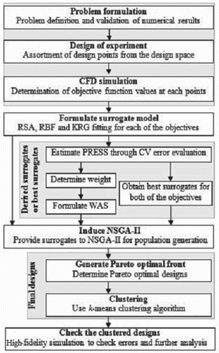
Figure shows the optimization strategy used in this study. It starts with problem formulations which include understanding the problem and deciding on the objective functions which need to be optimized and the design variables which influence these functions. In this study, two cases are used.
2.1. Problem formulation and numerical schemes
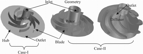
Case I involves a centrifugal pump impeller with a diameter (do) of 365 mm. Three design variables and two objectives were considered based on the literature (Bellary & Samad, Citation2014; Gulich, Citation2010; Luo et al., Citation2008); inlet angle (β1), exit angle (β2) and number of blades (G). The objective functions were to maximize efficiency and head. The geometric features of the impeller are shown in Table (Lazarkiewicz & Troskolanski, Citation1965).
Table 1. Features of impeller.
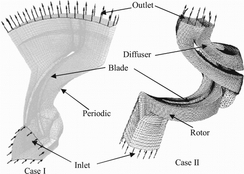
Computer-aided design (CAD) modeling and meshing of the flow domain were carried out using Ansys BladeGen and TurboGrid modules, respectively (Ansys CFX Citation13.Citation0, Citation2010). Ansys CFX 13.0 was used for the flow simulations. Table shows the meshing and boundary conditions. Further details regarding geometry, boundary conditions, validation and grid independence test can be found in Bellary and Samad (Citation2014).
Table 2. Meshing and boundary conditions.
Case II involved an ESP with a diameter of 100 mm. The impeller and diffuser were considered for the analysis, and two variables (inlet and outlet blade angles) along with two objectives (head and efficiency) were used for the optimization in this case. Figures & show the geometry and the flow domain of the ESP, and the impeller features are shown in Table . The simulations were carried out for an impeller at a speed of 3000 rpm with a discharge rate of Q = 0.0037 m3/s. The grid independence test was performed and an optimum number of nodes equal to 227,416 was selected. Mass flow inlet and pressure outlet boundary conditions are used at the inlet and outlet, respectively. Further details regarding the boundary conditions and flow simulation can be found in Table . The turbulence model used was k-ε which uses the scalable wall-function approach to improve robustness and accuracy as it efficiently captures near-wall boundary layer effects (Wilcox, Citation1994). The numerical results were validated with the experimental results given in Caridad, Asuaje, Kenyery, Tremante, and Aguillon (Citation2008).
The working fluid for both the cases was water of standard properties at a normal temperature and pressure. The performance of the pumps was calculated by solving the Reynolds-averaged Navier–Stokes (RANS) equations and used as design variable responses.
2.2. Design of experiment
After the completion of the problem formulation stage, a design space bounded by the two extreme (top and bottom) limits of the variables was created. The lower and upper bounds were determined via a literature survey (Bellary & Samad, Citation2014; Gulich, Citation2010; Li, Citation2002; Luo et al., Citation2008; Marsis et al., Citation2013; Ohta & Aoki, Citation1996), followed by simulations at the corners of the design space. A three-level full factorial design (Myers & Montgomery, Citation1995) was employed to choose the designs or design points from the design space. Once again, RANS equations were solved to obtain the design variable response that those design points. These responses were then used to construct the surrogate model.
2.3. Formulating the surrogate modeling
The surrogates used in this study are RSA, RBF, KRG and WAS. RSA is a polynomial function for responses generated from numerical calculations. The basic concept of a neural network or RBF is to learn from events. The RBF (Samad et al., Citation2008; Samad & Kim, Citation2008) comprises of a two-layer network. The first layer is a hidden layer of a radial basis function and the second is a linear output layer. The variables required to generate this surrogate model are a spread constant and a user-specified error goal, which comes from the mean input responses. The KRG (Husain & Kim, Citation2010) interpolation employs a known function for a large-scale variation and a function for a small-scale departure. The KRG model evaluated at some unsampled location has a global model and a systematic departure. The algorithm to construct a PoF through WAS and best PRESS surrogate (BPS) is as follows:
Algorithm 1. Algorithm for BPS- and WAS-assisted PoF.
Step1: Generate data from CFD analysis
Step2: Construct surrogates
Step3: Calculate PRESS
For BPS-BPS PoF
Step4a: Find least error and select surrogates for objective 1 and objective 2.
Step5a: Generate population for NSGA-II using the selected surrogates
Step6a: Generate PoF and cluster points
Step7a: Check errors with CFD analysis
For WAS-WAS PoF
Step 4b: Find weights for the surrogates and construct WAS for objective 1 and WAS for objective 2.
Step 5b: Generate population for NSGA-II using the WAS models
Step 6b: Generate PoF and cluster points
Step 7b: Check errors with CFD analysis
2.3.1. Weighted-average surrogate (WAS)
Generally, a large amount of data distributed in the design space fits a surrogate well, and the surrogate reflects the trend of the objectives. Any poorly-fitted surrogate may lead to unreliable results. The ensemble or averaged surrogates adequately refines the response trend of the data and insulates against bad surrogates (Goel et al., Citation2007; Queipo et al., Citation2005). A WAS model generated from the PRESS or CV errors (Sanchez et al., Citation2008) of the basic surrogates (RSA, KRG and RBF) was adopted in this problem. The predicted response of the WAS model is defined in Equation (1). In simplified form, the function can be written as
(2)
where Frsa, Fkrg, and Frbf are constructed using the CFD evaluated responses. A lower weight is assigned to the surrogate with a higher CV error, which means that the surrogate makes a reduced contribution to the construction of the WAS model.
In CV, the data is divided into k subsets of equal size. A surrogate is constructed k times, with each time excluding one of the subsets from training, and the excluded subset is used to evaluate the error. The k errors finally produce the error sum of squares. This process is known as leave-one-out CV. The calculation of the weights used in WAS is given in Goel et al. (Citation2007).
2.3.2. Best PRESS surrogate (BPS)
To implement a surrogate ensemble, the best surrogate must be selected from the available options. This can be achieved using a weighting scheme, and a weight equal to 1 is assigned to the surrogate with the least CV error. A 0 weight is allocated to the other models. This scheme is termed the BPS model (Goel et al., Citation2007) and is based on the concept of selecting a surrogate that gives the least CV error. In the present problem, the CV errors for the objectives were calculated separately and the surrogate which produced the least error was used for the PoF generation.
2.4. Non-dominated sorting of genetic algorithm-II (NSGA-II)
NSGA-II (Deb, Citation2001) is widely used in the scientific community. In the present problem, the algorithm is coupled with the Surrogates Toolbox (Viana, Citation2011; Viana et al., Citation2014) in order to make handling multiple functions easier. The relationships among the competitive objectives were established via the PoF produced by NSGA-II. The problem relates to two competing objectives (for each pump case), where the enhancement of one objective results in the degradation of the other. All feasible solutions related to the multi-objective problem are grouped into two types: dominated and non-dominated. The non-dominated solutions are designated as Pareto-optimal solutions. The objective functions are defined mathematically and estimated by numerical simulation. In this approach, an initial or parent population is arbitrarily established, and the objective function values are estimated for each design. Here, the term ‘population’ refers to the designs in the design space and the non-domination condition and crowding distance determine the rank of this population. Intermediate populations are created via selection, crossover and mutation by implementing a genetic operator. The populations (parent and intermediate) are combined, and the rank and crowding distance of the combined population is obtained. New populations are selected depending on the rank and crowding distance and are again ranked for the next generation based on the non-domination criteria. This process is reiterated until the limiting number of generations is attained.
2.5. k-means clustering
Five clusters in the global Pareto-optimal solutions were generated by the k-means clustering algorithm. This is a repeated-fitting process that generates the number of specified clusters. The clusters are distributed across the whole range of the PoF.
3. Results and discussion
3.1. Case I
Initially, three different variables (β1, β2 and G) affecting the performance of the pump (Lazarkiewicz & Troskolanski, Citation1965; Srinivasan, Citation2008) were selected and a parametric study was performed. The allocation of the angles was assured based on the literature (Li, Citation2002; Ohta & Aoki, Citation1996). Design points within the design space were selected from a three-level full factorial design method. The design space defined by the lower and upper limits of the variables is given in Table . The impeller passage was generated by polynomial curves at the inlet and the outlet, so that a small change in angle produces a continuous surface.
Table 3. Design variables with design space.
The surrogate which gives the least CV error was selected as the BPS. In Table , RSA shows the least CV error for both objectives, so it was selected as the BPS in both cases. The BPS was then used to generate populations using NSGA-II to build a BPS-BPS PoF (Figure ). Figure (a) shows the comparison of PoFs for different surrogates. The KRG-produced PoF designs are greatly distant from reality and can also be compared in the PRESS (Table ) which shows that the KRG-produced errors are the highest for both objectives. In Figure (b), the PoF at some cluster points of the KRG-KRG PoF show an efficiency of more than 100%, which is unrealistic for this type of simulation. The WAS-WAS PoF has higher fidelity.
Figure 4. Case I PoF and cluster points for (a) different surrogates and (b) selected cluster points.
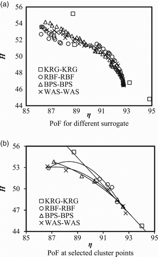
Table 4. PRESS for weights calculation.
Table 5. Surrogate-produced errors.
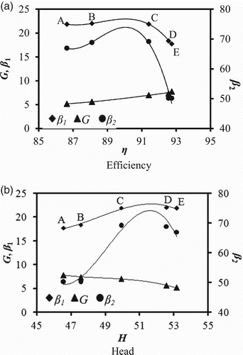
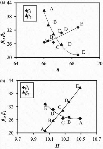
The design variable values (Figure ) are calculated for the cluster points. To get a higher efficiency, the number of blades should be increased and the inlet angle should be reduced. The exit angle initially increases the efficiency, but after attaining a certain efficiency it is reduced. Similarly for the head, the opposite phenomenon is observed (Figure (b)). Among different cluster points for the BPS, the one with a 59.63 exit blade angle (β2) is chosen and compared with other cluster points of different β2 values. In Table for different numbers of blades other than the designed one, the error is greater even though the exit blade angle has increased. For the other cases, the same surrogates, i.e., KRG-KRG and RBF-RBF were selected for both objectives. The combined error (CErr), which is the root mean square error (RMSE) of ηErr and HErr, is high for the KRG-KRG results and thus it made the least contribution to constructing the WAS model. The surrogates produce different values of PRESS; hence, the use of multiple surrogates or weighted surrogates is suggested. Table shows the PRESS errors and RMSEs of the BPS and WAS at different cluster points. All five clustered designs were simulated for comparison.
Table 6. Surrogate-produced errors for Case I.
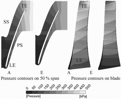
In Figure , the CFD results are compared for the two extreme cases (cluster points A and E in Figure (b)). The shock losses, secondary losses and hydraulic losses which reduce the hydraulic efficiency are greater at the off-design points (Lazarkiewicz & Troskolanski, Citation1965; Srinivasan, Citation2008). The head generation is augmented by an increase in β2 at the reference point. Here, an absolute flow velocity at the exit (c2) increases with an increase in the peripheral velocity (cu2), which enables a further increment in the dynamic head (Bellary & Samad, Citation2014; Gulich, Citation2010). The contours of total pressure at two extreme cluster points show that the highest pressure is generated at the impeller exit where the kinetic energy of flow attains a maximum level. This is because the pressure augments constantly with the mechanical energy supplied by the rotation of impeller and is then transformed into pressure energy. In the vicinity of the leading edge (LE) of the blade at the suction side, minimum pressure is observed (Figure ). An increase in blade angle increases the pressure difference between the outlet and inlet of the blade. The absolute velocity component (cu2) at the exit of the impeller increases with an increase in the discharge angle (Srinivasan, Citation2008).
This matches with the existing results (Lazarkiewicz & Troskolanski, Citation1965; Srinivasan, Citation2008), which state that an increase in β2 decreases the relative velocity and increases the total pressure.
3.2. Case II
In this case, a three-level full factorial design was also employed to find the designs from the design space (Table ) obtained from the literature (Li, Citation2002; Ohta & Aoki, Citation1996; Srinivasan, Citation2008). A polynomial curve makes a smooth impeller surface. The variables and responses were used to construct the KRG and RBF surrogates and the WAS was formulated using weighted averaging on these surrogates. The PRESS shows that the RBF is the best one for both objectives (Table ) and thus it selected for the BPS-BPS PoF construction. RSA and KRG produced the higher errors and so their contributions to the construction of the WAS model were least. Table shows the CFD results of the cluster points and their respective errors. The WAS-WAS generated points show the least error, while the KRG-KRG show the most error.
Figure (a) shows that the RSA-RSA PoF has a different trend in PoF unlike the WAS-WAS PoF and the BPS-BPS PoF trends. The errors in Table show that RSA produced the highest error for the efficiency. The cluster points and respective design variable values are shown in Figures and . The inlet angle (β1) increases if a higher efficiency is expected but the exit angle behaves in the opposite way. For a higher head, the opposite behavior of the variables can be observed (Figure (b)). Table shows that the WAS-WAS PoF has the least combined error (CErr). Table shows that the error is low in the WAS-WAS PoF and the BPS-BPS PoF.
Figure 7. Case II PoF and cluster points for (a) different surrogates and (b) selected cluster points.
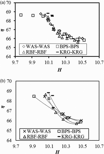
Table 7. Surrogate-produced errors for Case II.
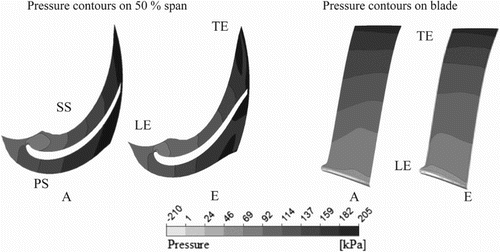
Figure shows the CFD calculations for two extreme points (designs A and E) from the clustered points of Figure (b). On the suction side and at 50% span, a low-pressure region appears in both the designs. The impingement of the flow on the LE causes a sudden loss in pressure. Also, a wider low-pressure region, which causes more flow losses and reduced efficiency, is present in design A as compared to design E. In Figure , the pressure increases from the LE to the trailing edge (TE) at different rates in both cases (designs A and E). A rapid pressure increase from LE to TE is observed in design A compared to design E, which generates more head in design A (Gulich, Citation2010). The values of efficiency and pressure head for these two cases are given in Table .
From the above analysis, it can be seen that the surrogates predict differently with different sets of data. The best surrogate for one set of data (Case I) produced the worst results for the other set (Case II). In Case I, the best surrogate was RSA, while it was RBF in Case II. The WAS model performed reliably or had higher fidelity with respect to CFD.
4. Conclusion
In this paper, a multiple-surrogate-assisted multi-objective optimization procedure is presented. The capability of surrogates to produce PoFs was evaluated with two examples of pump or turbomachinery design and optimization.
It was observed that the CV error is different for different surrogates and gives an indication of the degree of fit for each surrogate. A surrogate producing a high CV error is highly unreliable for generating a PoF. The verification with the CFD model shows that the error in Pareto designs is high for the surrogates which produce a high CV error. The BPS-produced PoF is better and can be used instead of any individual surrogate. The WAS-WAS PoF, which shows a robust result, is comparable to the BPS-BPS PoF. Hence, instead of using a single surrogate, the authors suggest the use of multiple surrogates to generate PoFs. A change in exit angle influences the augmentation of head and efficiency. The improvement in efficiency was due to the mitigation in flow loss in the disc friction losses outside of the impeller shroud and hub.
The BPS performs well for both cases and a wider design space or sparsely-distributed design points may require sequential sampling or multiple surrogate analysis.
Disclosure statement
No potential conflict of interest was reported by the authors.
Additional information
Funding
References
- Acar, E., & Rais-Rohani, M. (2009). Ensemble of metamodels with optimized weight factors. Structural and Multidisciplinary Optimization, 37(3), 279–294. doi: 10.1007/s00158-008-0230-y
- Ansys-CFX 13.0.Ansys Inc. 2010.
- Bellary, S. A. I., & Samad, A. (2014). An alternate approach to surrogate averaging for a centrifugal impeller shape optimization. International Journal of Computer Aided Engineering and Technology. Accepted for publication, 2014.
- Cao, S., Peng, G., & Yu, Z. (2004). Hydrodynamic design of rotodynamicpump impeller for multiphase pumping by combined approach of inverse design and CFD analysis. Journal of Fluids Engineering, 127(2), 330–338. doi: 10.1115/1.1881697
- Caridad, J., Asuaje, M., Kenyery, F., Tremante, A., & Aguillon, O. (2008). Characterization of a centrifugal pump impeller under two phase flow conditions. Journal of Petroleum Science and Engineering, 63(1–4), 18–22. doi: 10.1016/j.petrol.2008.06.005
- Collette, Y., & Siarry, P. (2003). Multiobjective optimization: Principles and case studies. New York: Springer.
- Couckuyt, I., Turck, F. D., Dhaene, T., & Gorissen, D. (2011). Automatic surrogate model type selection during the optimization of expensive black-box problems. Proceedings of the 2011 Winter Simulation Conference, December 11–14, Phoenix, AZ, USA.
- Cravero, C., & Macelloni, P. (2010). Design optimization of a multistage axial turbine using a response surface based strategy. Proceedings of the 2nd Int. Conference on Eng. optimization. 1–11.
- Deb, K. (2001). Multi-objective optimization using evolutionary algorithms (1st ed.). New York: John Wiley & Sons.
- Derakhshan, S., Pourmahdavi, M., Abdolahnejad, E., Reihani, A., & Ojaghi, A. (2013). Numerical shape optimization of a centrifugal pump impeller using artificial bee colony algorithm. International Journal of Computers & Fluids, 81, 145–151. doi: 10.1016/j.compfluid.2013.04.018
- Forrester, A. I. J., & Keane, A. J. (2009). Recent advances in surrogate-based optimization. Progress in Aerospace Sciences, 45(1–3), 50–79. doi: 10.1016/j.paerosci.2008.11.001
- Forrester, A. I. J., Sobester, A., & Keane, A. J. (2008). Engineering design via surrogate modeling: A practical guide. Chichester: John Wiley & Sons Ltd.
- Goel, T., Haftka, R. T., Shyy, W., & Queipo, N. V. (2007). Ensemble of surrogates. Structural and Multidisciplinary Optimization, 33(3), 199–216. doi: 10.1007/s00158-006-0051-9
- Gorissen, D., Couckuyt, I., Laermans, E., & Dhaene, T. (2010). Multiobjective global surrogate modeling dealing with the 5-percent problem. Engineering with Computers, 26(1), 81–98. doi: 10.1007/s00366-009-0138-1
- Gulich, J. F. (2010). Centrifugal pumps (2nd ed.). Berlin: Springer Publications.
- Houlin, L., Yong, W., Shouqi, Y., Minggao, T., & Kai, W. (2010). Effects of blade number on characteristics of centrifugal pumps. Chinese Journal of Mechanical Engineering, 23, 1–6. doi: 10.3901/CJME.2010.01.001
- Husain, A., & Kim, K. Y. (2010). Enhanced multi-objective optimization of a microchannel heat sink through evolutionary algorithm coupled with multiple surrogate models. Applied Thermal Engineering, 30(13), 1683–1691. doi: 10.1016/j.applthermaleng.2010.03.027
- Husain, A., Lee, K. D., & Kim, K. Y. (2011). Enhanced multi-objective optimization of a dimpled channel through evolutionary algorithms and multiple surrogate methods. International Journal for Numerical Methods in Fluids, 66(6), 742–759. doi: 10.1002/fld.2282
- Jin, M. (2011). Surrogate-assisted evolutionary computation: Recent advances and future challenges. Swarm and Evolutionary Computation, 1(2), 61–70. doi: 10.1016/j.swevo.2011.05.001
- Kamimoto, G., & Matsuoka, Y. (1956). On the flow in the impeller of centrifugal type hydraulic machinery (The 2nd report). Transactions of the Japan Society of Mechanical Engineers, Series 3. 22(113), 55–59. doi: 10.1299/kikai1938.22.55
- Lazarkiewicz, S., & Troskolanski, A. T. (1965). Impeller pumps (1st ed.). Oxford, London: Pergamonpress Ltd.
- Lee, Y., & Choi, D. H. (2014). Point wise ensemble of meta-models using ν nearest points cross-validation. Structural Multidisciplinary Optimization. 10.1007/s00158-014-1067-1
- Li, W. G. (2002). The influence of number of blades on the performance of centrifugal oil pumps. WorldPumps, 427, 32–35.
- Luo, X., Zhang, Y., Peng, J., Xu, H., & Yu, W. (2008). Impeller inlet geometry effect on performance improvement for centrifugal pumps. Journal of Mechanical Science and Technology, 22, 1971–1976. doi: 10.1007/s12206-008-0741-x
- Marjavaara, B. D., Lundstrom, T. S., Goel, T., Mack, Y., & Shyy, W. (2007). Hydraulic turbine diffuser shape optimization by multiplesurrogate model approximations of Pareto fronts. Transactions of the ASME., 129, 1228–1240. September 2007.
- Marsis, E., Pirouzpanahand, S., & Morrison, G. (2013). CFD-based design improvement for single-phase and two-phase flows inside an electrical submersible pump. ASME 2013 Fluids Engineering Division Summer Meeting, Incline village, Nevada, USA. FEDSM2013-16060, V01BT10A006; 8 pages. July 7–11.
- Myers, R. H., & Montgomery, D. C. (1995). Response surface methodology-process and product optimization using designed experiments. New York: John Wiley & Sons, Inc.
- Nguyen, A. T., Reiterand, S., & Rigo, P. A. (2014). Review on simulation-based optimization methods applied to building performance analysis. Applied Energy, 113, 1043–1058. doi: 10.1016/j.apenergy.2013.08.061
- Ohta, H., & Aoki, K. (1996). Effect of impeller angle on performance and internal flow of centrifugal pump for high viscosity liquids. Proceedings of the School of Engineering, Tokai University, 36(1), 159–168. 28.
- Peter, J., & Onera, M. M. (2008). Comparison of surrogate models for turbomachinery design. WSEAS Transactions on Fluid Mechanics, 3(1), 10–17.
- Queipo, N. V., Haftka, R. T., Shyy, W., Goel, T., Vaidyanathan, R., & Tucker, P. K. (2005). Surrogate based analysis and optimization. Progress in Aerospace Sciences, 41(1), 1–28. doi: 10.1016/j.paerosci.2005.02.001
- Robinson, T. D. (2007). Surrogate based optimization using multifidelity models with variable parameterization (PhD thesis). Massachusetts Institute of Technology.
- Rutter, R., Sheth, K., & O'Bryan, R. (2013). Numerical flow simulation and validation of an electrical submersible pump. ASME Proceedings, Symposiumon Applicationin CFD. Incline Village, Nevada, USA. 1A(FEDSM201316078),V01AT03A005; 7 pages. July 7–11, 2013. 10.1115/FEDSM2013-16078
- Samad, A. (2008). Numerical optimization of turbomachinery blade using surrogate models (PhD thesis). Inha University, Republic of Korea.
- Samad, A., & Kim, K. Y. (2008). Shape optimization of an axial compressor blade by multi-objective genetic algorithm. Proceedings of the Institution of Mechanical Engineers, Part A: Journal of Power and Energy, 222, 599–611.
- Samad, A., Kim, K. Y., Goel, T., Haftka, R. T., & Shyy, W. (2008). Multiple surrogate modeling for axial compressor blade shape optimization. Journal of Propulsion and Power, 24(2), 301–310. doi: 10.2514/1.28999
- Sanchez, E., Pintos, S., & Queipo, N. V. (2008). Toward an optimal ensemble of kernel-based approximations with engineering applications. Structural and Multidisciplinary Optimization, 36, 247–261. doi: 10.1007/s00158-007-0159-6
- Sanda, B., & Daniela, C. V. (2012). The influence of the inlet angle over the radial impeller geometry design approach with Ansys. Journal of Engineering Studies and Research, 18(4), 32–39.
- Shi, W., Long, F., Li, Y., Leng, H., & Zou, P. (2010). Non-overload design of low specific speed submersible pump. ASME 2010 3rd Joint US-European Fluids Engineering Summer Meeting. Montreal, Quebec, Canada. 1(FEDSM-ICNMM2010–30368), 563–567. August 1–5.
- Srinivasan, K. M. (2008). Rotodynamic pumps (1st ed.). New Delhi: New Age International (P) Ltd.
- Taormina, R., & Chau, K. (2015). Neural network river forecasting with multi-objective fully informed particle swarm optimization. Journal of Hydroinformatics, 17(1), 99–113. doi: 10.2166/hydro.2014.116
- Viana, F. A. C. (2011). SURROGATES toolbox user's guide version 3. Retrieved March 1, 2014, from http://sites.google.com/site/felipeacviana/surrogatestoolbox.
- Viana, F. A. C., Simpson, T. W., Balabanov, V., & Toropov, V. (2014). Metamodeling in multidisciplinary design optimization: How far have we really come? AIAA Journal, 52(4), 670–690. doi: 10.2514/1.J052375
- Wilcox, D. C. (1994). Turbulence modeling for CFD (2nd ed.). La Canada, California: DCW Industries, Inc.
- Zerpa, L. E., Queipo, N. V., Pintos, T. S., & Salager, J. L. (2005). An optimization methodology of alkaline surfactant polymer flooding processes using field scale numerical simulation and multiple surrogates. Journal of Petroleum Science and Engineering, 47, 197–208. doi: 10.1016/j.petrol.2005.03.002
- Zhang, J., & Chau, K. (2009). Multilayer ensemble pruning via novel multi-sub-swarm particle swarm optimization. Journal of Universal Computer Science, 15(4), 840–858.

