
 ?Mathematical formulae have been encoded as MathML and are displayed in this HTML version using MathJax in order to improve their display. Uncheck the box to turn MathJax off. This feature requires Javascript. Click on a formula to zoom.
ABSTRACT
After water flooding, there is much residual oil left in the pores. This cannot be easily displaced, but polymer flooding is able to achieve this. The use of viscoelastic solutions such as polymer can enhance the oil recovery, because it can increase the sweep volume by improving the mobility ratio of polymer solution and oil. The use of viscoelastic solutions can also increase the displacement efficiency of residual oil in the swept area. This article, based on the momentum equation and Oldroyd-B constitutive model, investigates the influences of polymer solution properties on the stress distribution and deformation of residual oil adhering to the walls of micro-channels. The results show that the elasticity and viscosity of the polymer displacing fluid are the factors with the greatest impact on the stress distribution and deformation of residual oil. The stress computation shows that along the direction of flow, the oil film is compressed at both ends, and pulled in the center. This stress distribution helps the oil film to bulge from its center, leading to its deformation and break-up. Furthermore, by increasing the viscosity or elasticity the residual oil is exposed to greater stress and deformation during the displacement process, which is characterized by a large advancing angle, an increasing deformation index and a small receding angle. Comparison of the simulation and experimental results shows a good conformance. Therefore, to displace the oil more efficiently, the polymer solutions need to be more viscous and elastic, which can be achieved by changing their chemical properties. The results clarify the micro-mechanism of polymers displacing residual oil and quantify the influences of the chemical properties of the solution on the stress, deformation and activation of residual oil.
1. Introduction
Chemical flooding is one of the most important enhanced oil recovery (EOR) technologies used to ensure stable oil production after water flooding, and it includes polymer flooding, surfactant flooding, alkali flooding or a combination of these methods, such as alkali/surfactant/polymer flooding (Bahrami, Kazemi, Mahdavi, & Ghobadi, Citation2016; Kamari, Gharagheizi, Shokrollahi, Arabloo, & Mohammadi, Citation2016; Shiran & Skauge, Citation2013; Wang, Liu, & Xu, Citation2013; Zhu, Hou, Jian, Ma, & Wang, Citation2013). Among these, polymer flooding is the most widely used technique since it is widely accepted that the addition of viscoelastic polymer to the injected fluid can greatly improve oil recovery. For example, in Daqing oil field, the biggest polymer flooding area in the world, polymer flooding has gone through four stages: indoor research, pilot field test, industrial field test and industrialization promotion. By June 2017, the accumulated oil production due to polymer flooding in Daqing oil field was 202 million tonnes, and this technique has played an important role in ensuring the continuous stable production of oil for 14 years. Polymer flooding can improve EOR since it can not only expand the sweep volume in multilayered reservoirs but also increase the displacement efficiency. On the one hand, the addition of polymers increases the viscosity of the water solution, which improves the mobility ratio between water and oil, thus enhancing the areal and vertical sweep efficiency and consequently increasing oil recovery (Li, Citation2006; Salehi, Hekmatzadeh, Sajjadian, & Masoumi, Citation2017; Urbissinova, Trivedi, & Kuru, Citation2010). On the other hand, in contrast to water flooding, the viscoelastic polymer solution can increase the displacement efficiency in the swept zone (Clarke et al., Citation2015; Yang, Li, Li, & Lan, Citation2007; Zhu, Luo, Klaus, & Fan, Citation2012). Comparison of the oil displacement efficiency of different types of water solution shows that the oil displacement efficiency of viscoelastic polymer solution is higher than that of non-elastic displacing fluid, and the contribution of elasticity to the oil displacement efficiency is about 40% (Wang, Wang, Wu, Xia, & Yin, Citation2008; Wu & Wang, Citation2011; Xia, Wang, Zhang, & Feng, Citation2012).
The residual oil is normally scattered in the micro-spaces. The residual oil after water flooding can be divided into five categories: oil drop, column, film, cluster and dead-end oil. Among these, the oil-film type is the richest in quantity and the most widely distributed. Some theoretical and experimental work has been performed to study the mechanisms by which polymer solutions displace residual oil after water flooding. For example, contact angle and zeta potential measurements indicate that the recovery mechanism involves altering the wettability (Almansour, Alquraishi, AIHussinan, & AIYami, Citation2017). Other experiments show that low-saltwater-containing polymer can also change the wettability and improve the oil displacement efficiency (Khorsandi, Qiao, & Johns, Citation2017). However, during polymer-surfactant flooding, the nanoparticle pulling and emulsification mechanisms are more effective than alterations to the wettability (Sedaghat, Mohammadi, & Razmi, Citation2016). Moreover, the rheology of polymer solution in micro-channels, including dead ends, has been studied by some researchers and it is considered that the greater the viscoelasticity of the displacement solution, the larger the sweep volume and stress on the residual oil (Yin, Wang, & Zhong, Citation2006; Zhang & Yue, Citation2008). In addition, numerical calculations show that the dispersion phenomenon reduces the displacement efficiency (Sharafi & Jamialahmadi, Citation2016). Using computational fluid dynamics to simulate liquid or gas flow is helpful to gain appropriate insight into the flow features (Ghalandari, Koohshahi, Mohamadian, Shamshirband, & Chau, Citation2019; Mosavi, Shamshirband, Salwana, Chau, & Tah, Citation2019), and is also very suitable for simulating the liquid–liquid two-phase flow.
Although many scholars have undertaken research, the mechanism by which viscoelastic polymer displaces residual oil in micro-channels is not well understood and many problems remain unresolved. For example, in micro-channels, the computation of the stress and deformation of residual oil has not been resolved, and visual experiments on the residual oil have not been carried out. In this paper, both computational and experimental studies are performed to analyze the effects of polymer solutions on the deformation of residual oil. It is widely accepted that viscoelastic polymer solution can improve the oil displacement efficiency, owing to the stress variation exerted on the oil, which leads to its deformation and detachment. As such, it is imperative to study the flow-field characteristics, stress distribution and deformation law of residual oil. The stress distribution and deformation of the residual oil adhering to the wall surface in micro-channels where the viscoelastic polymer solution flows are investigated based on the momentum equation. For this, the Oldroyd-B fluid constitutive model is selected to build a viscoelastic fluid flow equation, and thus analyze the influence of viscoelastic properties on the stress distribution and deformation. The results could be useful in quantifying the activating conditions of residual oil and clarifying the micro-mechanism of residual oil displacement by polymer solution.
2. Mathematical models
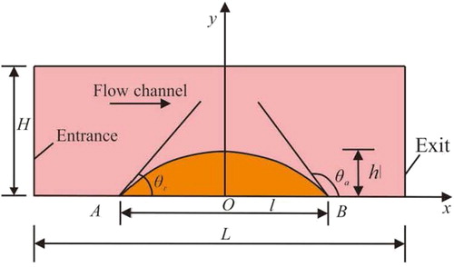
The micro-channels of complex shapes in the rocks are simplified and the residual oil is in the form of an oil film, soundly adhering to the surface of the pores. The geometric model of the flow channel is simplified and shown in Figure , where L denotes the length of the flow channel, H denotes the width of the channel, l denotes the length of the residual oil and h denotes the height of the residual oil.
Figure 1. Flow channel domain (orange denotes residual oil, pink denotes polymer solution).
Under the pressure difference, the viscoelastic fluid flows along the x-axis. Since [where Bo denotes the Bond number (dimensionless), g denotes gravitational acceleration (m/s2), σ denotes the interface tension between the polymer solution and residual oil (N/m), ρp denotes the density of polymer solution (kg/m3), and ρo denotes the density of residual oil (kg/m3)], the influence of gravity can be ignored. The fluid undergoes isothermal and laminar flow in the micro-channel, leaving some oil on the bottom of the wall of the micro-channel. Since it is assumed that the flow channel is smooth, the impact of the boundary layer is also ignored. In addition, the interface between the residual oil and channel wall is oil-wet under the initial conditions and the interface between the viscoelastic fluid and oil is movable with time. The meshing of the calculation domain in the initial state is shown in Figure .
Figure 2. Meshing of the calculation domain.
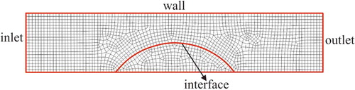
The whole domain is divided into quadrilateral grids (Xi, Xiong, & Pu, Citation2019). It is assumed that L = 10h, H = 2h, l = 4h, where h denotes the height of the initial residual oil, so the flow channel covers a total of 1758 grids and the residual oil covers 301 grids; through the grid independence test, the computational grid used in this paper can achieve accurate results.
During flow, an adaptive grid is used to prevent the front end at the interface of the viscoelastic fluid and residual oil from deforming excessively. Since the interface between the viscoelastic fluid and residual oil is a mobile boundary, the interfacial tension should be taken into consideration when establishing the equation of momentum, shown in Equation (Equation1(1)
(1) ):
(1)
(1) where ρ denotes density (kg/m3), u denotes velocity (m/s), T denotes the stress tensor, σ denotes the interfacial tension between the displacement solutions and residual oil (a constant value in this paper) (N/m),
denotes the surface of residual oil covering point xB,
denotes the curvature of the surface of residual oil (1/m), n denotes the outer unit vector in the normal direction of the oil surface, and δ(x − xB) is a second-order δ function. For ease of numerical calculation, interfacial tension is deemed as the source item of Equation (Equation1
(1)
(1) ).
The stress imposed on the surface of the oil film is decomposed in the normal and tangential direction, as shown in Figure , where τnτ denotes tangential stress and τnn denotes normal stress.
Figure 3. Diagram of stress tensor acting on residual oil.
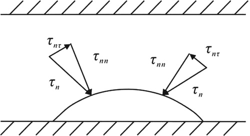
Since T denotes the stress state at one point on the surface of the residual oil film, along the normal direction n, the stress is expressed as:
(2)
(2) The tangential stress τnτ and the normal stress τnn can be obtained through the scalar product between stress tensor T and the unit vectors in the tangential direction and the normal direction at some point, respectively. In this paper, unless otherwise specified, the stress in the normal direction is positive under compression and negative under tension; the stress in the tangential direction is positive when it is the same as the flow direction; otherwise it is negative.
The Oldroyd-B fluid constitutive model is used to simulate the rheological behavior of the polymer solution. This is logical since the Oldroyd-B constitutive model is a viscoelastic fluid model. In addition, it is relatively simple, as shown in Equation (Equation3(3)
(3) ):
(3)
(3) where λ1 denotes the relaxation time (s), λ2 denotes retardation time (s), η0 denotes zero shear viscosity (Pa·s), A denotes the deformation tensor of the first-order Rivlin–Ericksen,
denotes the upper-convected derivative of T, and
denotes the upper-convected derivative of A.
The process of polymer solutions flowing through the pores is an example of two-phase flow, in which the residual oil is the dispersed phase and the polymer solutions are the continuous phase. The polymer solutions are viscoelastic fluid, but the residual oil is inelastic non-Newtonian fluid (assume that the residual oil is a Newtonian fluid with fixed density and viscosity, and this does not change with time), so they have different rheological behaviors. Moreover, the interface between the polymer and residual oil will deform with time in the flowing process. As such, the interface formation can be captured with interface tracking methods. In this paper, the Lagrange interface tracking method is used to track and reconstruct the shape of the interface (Aggarwal, Citation2007).
For the flow of viscoelastic polymer solution, the removal of pure viscosity items from the stress tensor will cause the convergence problem of the momentum equation during calculation. Even with pure viscosity items, the convergence of the equation will gradually become worse as the Weissenberg number (We) increases. To solve this problem, the total stress tensor changes elastic-viscous stress (EVSS) method has been proposed (Rajagopalan, Armstrong, & Brown, Citation1990; Rajagopalan, Byars, Armstrong, & Brown, Citation1992). If the total stress tensor contains no Newtonian viscosity items, the momentum equation will lose its ellipticity. In fact, even with an elliptical item, the equation will gradually lose its ellipticity as the Weissenberg number increases.
3. Influence of viscoelastic polymer properties on stress distribution
Four dimensionless parameters are defined based on the initial height h of the residual oil and the shear rate G at the entrance of the flow channel. The Reynolds number (Re) (Equation Equation4(4)
(4) ) is the inertia force divided by the viscous force and can reflect the flow state. A smaller Re implies a higher viscous force and therefore denotes a laminar flow. The Weissenberg number (We) (Equation Equation5
(5)
(5) ) is the first normal stress difference divided by double viscous force, and reflects the elasticity of the polymer solution. A higher We implies a more elastic fluid. The capillary number (Ca) (Equation Equation6
(6)
(6) ) is the viscous force divided by interfacial tension, and reflects the deformation and break-up of residual oil. A greater capillary number implies that the oil film is more prone to deformation. The viscosity ratio (λμ) (Equation Equation7
(7)
(7) ) is the viscosity ratio of the residual oil and polymer solution.
(4)
(4)
(5)
(5)
(6)
(6)
(7)
(7) where ρp denotes the density of the polymer solution (kg/m3), G denotes the shear rate of the channel entrance (1/s), μp denotes the viscosity of the polymer solution (Pa·s), N1 denotes the first normal stress difference (Pa), τ denotes the shear stress (Pa), and μo denotes the viscosity of the residual oil (Pa·s).
It is assumed that the residual oil is static, so the polymer solution is under steady-state flow during displacement and the last item of Equation (Equation1(1)
(1) ) is zero. However, as this constitutive equation is nonlinear, in the process of calculation, evolution is applied for the elasticity item gradually changing from inelastic to a preset value. Some parameters for the calculation are listed in Table . In addition, the flow channel is 20 µm wide and 100 µm long; and the residual oil film is 40 µm long and 10 µm high.
Table 1. Basic input parameters for calculation.
3.1. Influence of viscoelastic polymer properties on normal stress
The normal stress is perpendicular to the residual oil surface, causing the oil to bulge or dent in the normal direction, and making it easier to enlarge the local deformation of residual oil. The curves reflecting how the normal stress changes with the viscosity ratio λμ and the Weissenberg number We are shown in Figure . Several phenomena can be observed.
Figure 4. Normal stress changes with (a) viscosity ratio (We = 0.2) and (b) Weissenberg number (λμ = 1).
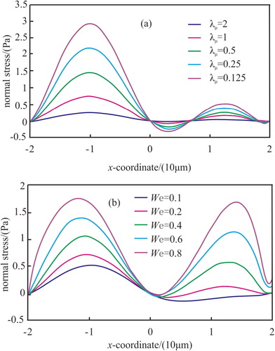
First, the lower the viscosity ratio, the higher the normal stress on the residual oil. Second, with increased We, which means that the elasticity of the displacement agent increases, the normal stress on the residual oil will increase. Third, along the x-axis direction, on the left side of the residual oil, the normal stress increases first and then gradually decreases after reaching its peak value, and the oil stays compressed; at the middle of the residual oil, the normal stress is negative, implying that the oil film is being pulled; on the right side of the film along the x-axis, the normal stress turns positive, implying that the film is still being compressed. In this context, the film is pulled at a small area in the middle and compressed elsewhere, and such a distribution of normal stress can help the residual oil to bulge from its center and deform under continuous action of the displacement agent.
Here, to prove that the quadrilateral grids are suitable for the computation, the unstructured grids are presented for comparison, as shown in Figure .
Figure 5. Meshing of the calculation domain with unstructured grids.
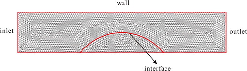
The whole domain is divided into unstructured grids, the flow channel covers a total of 3992 grids and the residual oil covers 702 grids; the number of unstructured grids is much more than the quadrilateral grids. Taking the normal stress as an example, with the same We = 0.2 and the same viscosity ratio λμ = 1, the change curve of normal stress in different grids is compared in Figure .
Figure 6. Normal stress changes with different meshing.
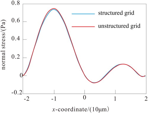
Although the meshing of the calculation domain is different, the change curves of normal stress almost overlap. Therefore, using quadrilateral grids is feasible.
3.2. Influence of viscoelastic polymer properties on tangential stress
The tangential stress occurs along the tangential direction of the residual oil film, and the angular deformation will be enhanced as tangential stress increases. Figure shows how the tangential stress changes with λμ and We.
Figure 7. Tangential stress changes with (a) viscosity ratio (We = 0.2) and (b) Weissenberg number (λμ = 1).
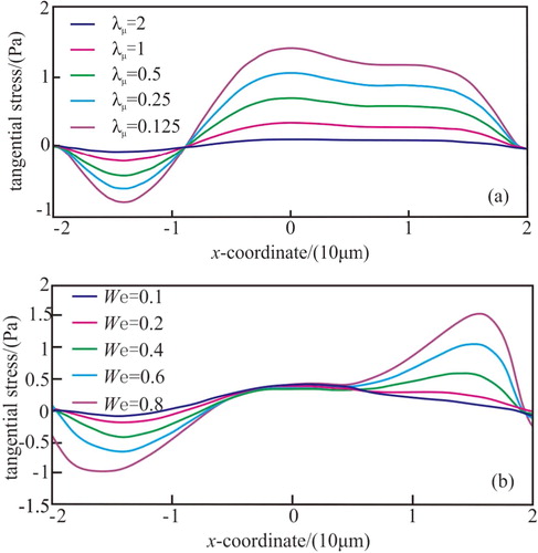
It can be seen that there is a demarcation point between one-quarter and one-half of the oil film along the flow direction; before this point, tangential stress is negative, and beyond this point, it becomes positive. Moreover, the lower the viscosity ratio, or the higher the elasticity, the stronger the tangential stress. Since viscoelastic fluid has memory, the elasticity of the displacement agent has a hysteresis effect on the peak value of the tangential stress.
Some researchers (e.g. Wang et al., Citation2008; Wu & Wang, Citation2011; Xia et al., Citation2012) have proposed the existence of micro-forces, but only qualitatively analyzed the stress of residual oil. In this paper, the normal stress and tangential stress are the micro-force.
4. Influence of viscoelastic polymer properties on deformation of residual oil
Two types of force applied on the residual oil during the displacement process are differential pressure and viscoelastic force. The differential pressure, which is a macro-force, serves as the most crucial displacing force for the residual oil to be activated from the rock surface. When the differential pressure is stronger than the adhesion of rock to residual oil, the residual oil will be fully activated from the surface of the rock after wetting hysteresis. In addition, since the polymer solution is viscoelastic, the oil is also subjected to viscoelastic force, which is a type of micro-force (Wang et al., Citation2008). The micro-force is weaker than the macro-force, but when the macro-force is insufficient to fully displace the residual oil, the micro-force can make the residual oil deform and break into small drops by changing the stress distribution on the oil, and finally achieve the purpose of displacement.
4.1. Influence of viscosity ratio on the deformation of residual oil
The dimensions of the flow channel and residual oil, as well as the basic parameters of the displacement agent, stay unchanged. For the calculations, it is assumed that the interfacial tension is 0.001 mN/m, We is 0.4 and t is 0.4 s. Figure shows how the residual oil deforms as the viscosity ratio changes.
Figure 8. Residual oil deformation in terms of viscosity ratio.
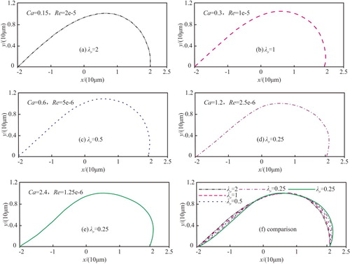
It can be concluded that at a smaller viscosity ratio, which implies that the displacement agent becomes more viscous, the capillary number increases, which will make the residual oil more notably deformed. The advancing angle and the receding angle, which refer to the advancing angle gradually enlarging at the oil film downstream and the receding angle gradually contracting at the oil film upstream along the flow direction, respectively, have been calculated and are listed in Table .
Table 2. Advancing angle and receding angle changes with λμ.
As the viscosity ratio reduces, the advancing angle of the residual oil increases, while the receding angle of the residual oil decreases, so the deformation of the residual oil grows more notably. It is assumed that the adhesion of rock to residual oil is very strong, so the three-phase contact points stay still. If the adhesion fails to resist the displacement force imposed by the viscoelastic polymer, when the receding angle decreases and reaches its critical value, point A in Figure will slide forward; and when the advancing angle increases and reaches its critical value, point B in Figure will slide forward, making the residual oil slide forward.
Another parameter, the deformation index, is defined in Equation (Equation8(8)
(8) ) to show the deformation amplitude of the residual oil. The dotted line in Figure (a) is the surface of the undeformed residual oil, while the solid line in Figure (b) is the new location of the deformed residual oil. A large D implies deformation of the residual oil.
(8)
(8) where, li denotes the length of the deformed residual oil, hi denotes the height of the deformed residual oil, l denotes the length of the undeformed residual oil, h denotes the height of the undeformed residual oil, and D denotes the deformation index. The relation between the deformation index and viscosity ratio is shown in Figure .
Figure 9. Comparison of residual oil (a) before and (b) after deformation.
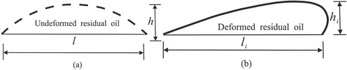
Figure 10. Relationship between deformation index and viscosity ratio.
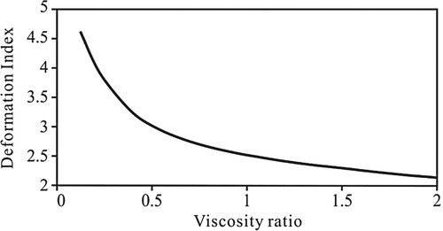
The deformation index changes inversely with the viscosity ratio, i.e. the lower the viscosity ratio, the higher the deformation index. When the viscosity ratio is less than 1, which means that the viscosity of the viscoelastic displacement solution is high but the viscosity of the residual oil is small, the deformation index curve is of exponential type. Thus, the deformation of the residual oil can be enhanced by making the viscoelastic polymer solution more viscous, which is normally achieved by increasing the molecular weight or concentration of the solution in the field (Liu, Yang, & Fan, Citation2017).
4.2. Influence of elasticity on the deformation of residual oil
With other conditions unchanged, set Re = 5e-6, Ca = 0.6 and t = 0.4 s. Figure shows how the residual oil changes with We. Figure shows how the deformation index changes with We. The advancing and receding angles of the deformed residual oil are listed in Table .
Figure 11. Relationship between oil deformation and Weissenberg number (We).
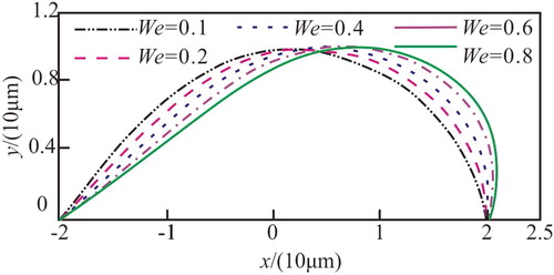
Figure 12. Relationship between deformation index and Weissenberg number (We).
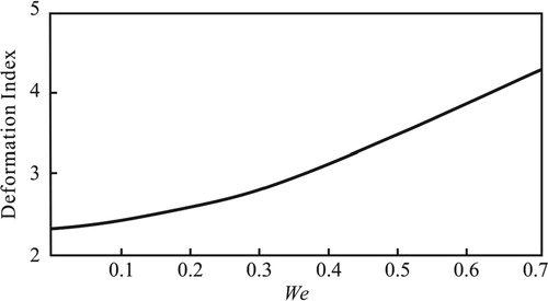
Table 3. Advancing angle and receding angle changes with We.
It can be seen that elasticity becomes one of the important parameters affecting the deformation of the residual oil. Conclusively, with the increase in We, the advancing angle of the oil film increases, the deformation index D increases and the receding angle decreases, implying that the residual oil's deformation is enhanced as the displacement agent becomes more elastic, as shown in Figure .
Limited by the calculation conditions, the maximum of We can only be 0.8; as the solution keeps growing more elastic, the deformation index increases exponentially and the deformation will be more notable, as shown in Figure .
5. Comparison with laboratory experimental results
To visualize how a residual oil film in a micro-channel deforms, breaks up and activates, a laboratory experiment is conducted. For this experiment, a transparent core (size: 40 × 40 mm) etched on glass has been made based on the pore structure of a natural core on a cast slice. The oil is a mixture of kerosene and crude oil produced by No. 2 Oil Extraction Factory of Daqing oil field (viscosity: 20 mPa·s at 45°C). The polymer for this experiment is mainly composed of polyacrylamide, with a relative molecular weight of 19 × 106, produced by Daqing refining and chemical company. The water has a salinity of 508 mg/l. The displacement is carried out in a micro-model incubator at a temperature of 45°C, whereby a polymer solution of 1500 mg/l is injected through a 20 µm flow channel in the core at 2 × 10⁻¹⁰ m3/s constantly. The deformation and detachment process of the oil film has been recorded on a video recorder and is shown in Figure .
Figure 13. Deformation and detachment process of residual oil.
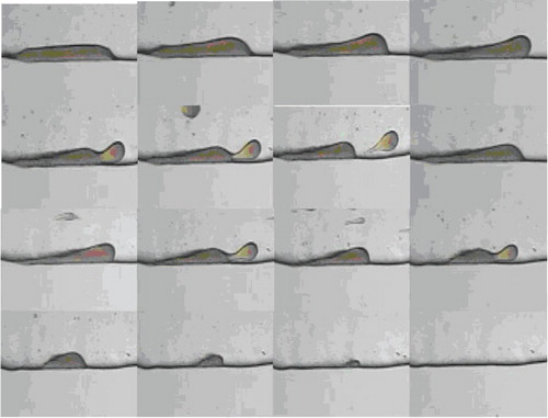
It can be observed that after water flooding, some oil is left on the surface of the rock in the form of film, and it turns thicker and thicker along the flow direction as the polymer displacement agent works, forming a bulge. When any part of the bulge reaches its stress limit (i.e. the displacement force exceeds the cohesive force of residual oil) under the continuous displacement force, the bulge will deform and finally break up into small oil drops. The separated oil drops will be displaced. These processes will continue and repeat until the film-like residual oil has been fully displaced.
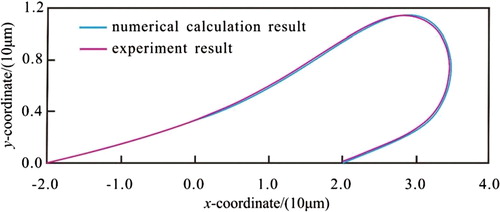
The simulation and in-house experimental results are compared to verify the accuracy of the models. For the simulation, the width of the channel is 20 µm and We = 0.4. For the experiment, the concentration of the solution is 1500 mg/l, which means that We is 0.4, according to the elastic calculation. The numerical simulation results conform to the results of the experiment, as shown in Figure .
Figure 14. Comparison of numerical calculation and experimental results.
6. Conclusions and discussion
The micro-mechanism for the displacement of residual oil by polymer solutions has been clarified in this study. Viscoelastic polymer solutions can increase displacement efficiency, owing to the stress distribution variation acting on the oil, which leads to its greater deformation. The elasticity and viscosity of polymer solutions are the most important factors affecting the stress distribution and deformation.
The stress distributions on the residual oil film and its deformation have been studied based on mathematical models. The normal stress causes the oil to bulge or dent in the normal direction and deform. Along the flow direction, the oil film is compressed at both ends and pulled in the center, and this distribution can help the film to bulge from its center, deform and detach; by increasing the viscosity or elasticity, the normal stress can be increased.
Parameters such as advancing and receding angles and the deformation index are defined to quantify the deformation of oil during the displacement process. By increasing the elasticity or viscosity, the deformation index increases progressively, the advancing angle increases and the receding angle decreases. Therefore, the deformation of residual oil can be enhanced by making the polymer solution more viscous and elastic, which is achieved by increasing the concentration or molecular weight of the polymer in the oil field.
In this paper, in the process of displacement of the residual oil by a viscoelastic fluid, the stress and deformation of the residual oil are simulated numerically. However, owing to the limitations of the experimental conditions, the critical advancing angle, receding angle, break-up and separation conditions of residual oil were not obtained. The next task is to determine the activating conditions of residual oil.
Disclosure statement
No potential conflict of interest was reported by the authors.
Additional information
Funding
References
- Aggarwal, N. (2007). Computational viscoelastic drop dynamics and rheology (Ph.D. Thesis). University of Delaware, USA.
- Almansour, A. O., Alquraishi, A. A., AIHussinan, S. N., & AIYami, H. Q. (2017). Efficiency of enhanced oil recovery using polymer-augmented low salinity flooding. Journal of Petroleum Exploration and Production Technology, 7, 1149–1158. doi: 10.1007/s13202-017-0331-5
- Bahrami, P., Kazemi, P., Mahdavi, S., & Ghobadi, H. (2016). A novel approach for modeling and optimization of surfactant/polymer flooding based on genetic programming evolutionary algorithm. Fuel, 179, 289–298. doi: 10.1016/j.fuel.2016.03.095
- Clarke, A., Howe, A. M., Mitchell, J., Staniland, J., Hawkes, L., & Leeper, K. (2015). Mechanism of anomalously increased oil displacement with aqueous viscoelastic polymer solutions. Soft Matter, 11(18), 3536–3541. doi: 10.1039/C5SM00064E
- Ghalandari, M., Koohshahi, E. M., Mohamadian, F., Shamshirband, S., & Chau, K. W. (2019). Numerical simulation of nanofluid flow inside a root canal. Engineering Applications of Computational Fluid Mechanics, 13(1), 254–264. doi: 10.1080/19942060.2019.1578696
- Kamari, A., Gharagheizi, F., Shokrollahi, A., Arabloo, M., & Mohammadi, A. H. (2016). Integrating a robust model for predicting surfactant–polymer flooding performance. Journal of Petroleum Science and Engineering, 137, 87–96. doi: 10.1016/j.petrol.2015.10.034
- Khorsandi, S., Qiao, C., & Johns, R. T. (2017). Displacement efficiency for low-salinity polymer flooding including wettability alteration. SPE Journal, 22, 417–430. doi: 10.2118/179695-PA
- Li, Y. (2006). Experimental studies of physical simulation on polymer flooding in the large-scale areal models (Ph.D. Thesis). Institute of Porous Flow and Fluid Mechanics, Chinese Academy of Science, Langfang, China.
- Liu, L., Yang, S., & Fan, J. (2017). Stress calculation of polymer displacing residual oil in micro pores. International Journal of Performability Engineering, 13(2), 211–220.
- Mosavi, A., Shamshirband, S., Salwana, E., Chau, K. W., & Tah, J. (2019). Prediction of multi-inputs bubble column reactor using a novel hybrid model of computational fluid dynamics and machine learning. Engineering Applications of Computational Fluid Mechanics, 13(1), 482–492. doi: 10.1080/19942060.2019.1613448
- Rajagopalan, D., Armstrong, R. C., & Brown, R. A. (1990). Finite element methods for calculation of steady viscoelastic flow using constitutive equations with a Newtonian viscosity. Journal of Non-Newtonian Fluid Mechanics, 36, 159–192. doi: 10.1016/0377-0257(90)85008-M
- Rajagopalan, D., Byars, J. A., Armstrong, R. C., & Brown, R. A. (1992). Comparison of numerical simulations and birefringence measurements in viscoelastic flow between eccentric rotating cylinders. Journal of Rheology, 36(7), 1349–1375. doi: 10.1122/1.550266
- Salehi, M. M., Hekmatzadeh, A., Sajjadian, V. A., & Masoumi, M. (2017). Simulation of polymer flooding in one of the Iranian oil fields. Egyptian Journal of Petroleum, 26(2), 325–330. doi: 10.1016/j.ejpe.2016.05.001
- Sedaghat, M. H., Mohammadi, H., & Razmi, R. (2016). Application of SiO2 and TiO2 nano particles to enhance the efficiency of polymer-surfactant floods. Energy Sources, Part A: Recovery, Utilization, and Environmental Effects, 38(1), 22–28. doi: 10.1080/15567036.2012.740552
- Sharafi, M. S., & Jamialahmadi, M. (2016). Investigation and quantifying effect of dispersion on oil recovery in the process of viscoelastic polymer flooding using numerical method. Petroleum Science and Technology, 34(15), 1333–1339. doi: 10.1080/10916466.2016.1198808
- Shiran, B. S., & Skauge, A. (2013). Enhanced oil recovery (EOR) by combined low salinity water/polymer flooding. Energy & Fuels, 27(2), 1223–1235. doi: 10.1021/ef301538e
- Urbissinova, T. S., Trivedi, J., & Kuru, E. (2010). Effect of elasticity during viscoelastic polymer flooding: a possible mechanism of increasing the sweep efficiency. Journal of Canadian Petroleum Technology, 49(12), 49–56. doi: 10.2118/133471-PA
- Wang, J., Liu, H., & Xu, J. (2013). Mechanistic simulation studies on viscous-elastic polymer flooding in petroleum reservoirs. Journal of Dispersion Science and Technology, 34(3), 417–426. doi: 10.1080/01932691.2012.660780
- Wang, D., Wang, G., Wu, W., Xia, H., & Yin, H. (2008). Influence of the micro-force produced by viscoelastic displacement liquid on displacement efficiency. Journal of Xi’an Shiyou University (Natural Science Edition), 23(1), 43–55.
- Wu, W., & Wang, D. (2011). Research on improving oil displacement efficiency using viscoelastic behavior of polymer. Journal of China University of Petroleum, 35(5), 134–138.
- Xia, H., Wang, D., Zhang, J., & Feng, H. (2012). Quantitative description of contribution of elasticity of polymer solution to oil displacement efficiency. Journal of Petro Chemical Universities, 4(36), 166–176.
- Xi, P., Xiong, Y., & Pu, J. (2019). Mesh comparison on E799A cavitation performance based on Fluent. Ship Science and Technology, 41(4), 30–33.
- Yang, Q., Li, B., Li, Y., & Lan, Y. (2007). Calculation method research on sweep efficiency and displacement efficiency in polymer flooding. Daqing Petroleum Geology and Development, 26(1), 109–112.
- Yin, H., Wang, D., & Zhong, H. (2006). Study on flow behaviors of viscoelastic polymer solution in micro pore with dead end. SPE Annual Technical Conference and Exhibition, San Antonio, Texas, USA, 24–27 September, SPE101950.
- Zhang, L., & Yue, X. (2008). Displacement of polymer solution on residual oil trapped in dead ends. Journal of Central South University of Technology, 15(1), 84–87. doi: 10.1007/s11771-008-0320-4
- Zhu, Y., Hou, Q., Jian, G., Ma, D., & Wang, Z. (2013). Current development and application of chemical combination flooding technique. Petroleum Exploration and Development, 40(1), 90–103. doi: 10.1016/S1876-3804(13)60009-9
- Zhu, H., Luo, J., Klaus, O., & Fan, Y. (2012). The impact of extensional viscosity on oil displacement efficiency in polymer flooding. Colloids and Surface. A: Physicochemical and Engineering Aspects, 414, 498–503. doi: 10.1016/j.colsurfa.2012.08.005