
 ?Mathematical formulae have been encoded as MathML and are displayed in this HTML version using MathJax in order to improve their display. Uncheck the box to turn MathJax off. This feature requires Javascript. Click on a formula to zoom.
Abstract
This article proposes a novel a magnetophoretic microfluidic device for separation of magnetic microparticles based on size and subsequently carries out simulation-based parametric analysis of the same. The microfluidic device is constructed with two inlets as well as two outlets and employs a soft magnetic element subjected to a uniform magnetic field to create the desired spatially varying magnetic field inside the microchannel. The first inlet introduces the sample while the second inlet is for introducing sheath flow to focus the microparticles close to the microchannel’s bottom surface prior to being deflected by magnetophoresis to the appropriate outlets. Parameters such as location of outlets, microchannel height, fluid velocity, and ratio of inlet and of outlet flow rates influence the movement of microparticles inside the microchannel and the associated performance metrics. Parametric study, carried out using 1 and 10 µm magnetic microparticle suspended in water, revels that the best performance metrics occur when flow rate ratios are maintained as low as possible. In addition, the performance metrics are examined for different designs to determine the optimal value of the location of the outlet associated with large microparticles.
Introduction
Microfluidic devices are those that employ flow passages with small hydraulic diameters (<1 mm) (Mathew & Weiss, Citation2015). There are several advantages in employing in microscale flow passages including reduced requirement for sample and reagents, small footprint and portability, and minimal power consumption (Mark et al., Citation2010). Microfluidic devices are employed for a wide range of applications which includes splitting of a sample of microparticles with dissimilar properties into samples with similar properties. There are two types of separation of microparticles; one is size-based and the other is type-based. In size-based separation, the microparticles in each homogeneous sample have same size. On the other hand, in type-based separation the microparticles in each homogeneous sample are of the same type. Irrespective of the category of separation, microparticles need to be acted upon by actuation forces for achieving separation (Lee et al., Citation2016). There are several actuation mechanisms, including magnetophoresis, for purposes of separation in microfluidic devices. Magnetophoresis is the phenomenon that describes the translation of microparticles that are exposed to a spatially varying magnetic field while being dispersed in a medium; when the medium is diamagnetic and magnetic then the microparticle needs to be magnetic and diamagnetic, respectively (Alnaimat et al., Citation2018). For the combination of magnetic microparticles and diamagnetic medium, the magnetic microparticle moves toward the highest gradient of the spatially varying magnetic field and this phenomenon is specific termed as positive magnetophoresis (Alnaimat et al., Citation2018). On the other hand, for diamagnetic microparticles dispersed in a magnetic medium, the diamagnetic microparticle translate to the lowest gradient of the spatially varying magnetic field and this phenomenon is terms as negative magnetophoresis (Alnaimat et al., Citation2018). The primary advantage of magnetophoresis over other actuation mechanisms is that it can handle relatively high flowrates. Additionally, the fabrication is relatively easy when soft magnetic elements and permanent magnets are used to realize magnetophoresis.
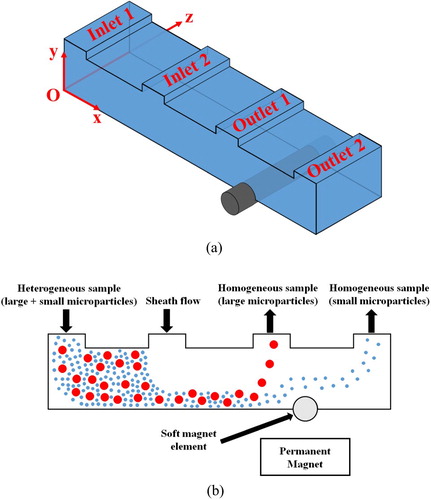
This article details a microfluidic device that employs magnetophoresis for separation of magnetic microparticles, dispersed in a diamagnetic medium, based on size. Figure is the schematic of the envisioned microfluidic device. The device employs a cylindrical soft magnetic element at the bottom of the microchannel; only the top half of this magnetic element is in contact with the medium. A uniform external magnetic field is applied perpendicular to the longitudinal axis of the soft magnetic element and this causes the magnetic field near the soft magnetic element to be varying. The microfluidic device has two inlets with the first inlet for introducing the sample while the second inlet is used for introducing sheath flow that is needed for focusing of the microparticles introduced at the first inlet. The microparticles are focused near the microchannel’s bottom surface before reaching the soft magnetic element. As the magnetic microparticle nears the leading edge of the soft magnetic element, it experiences repulsive magnetophoretic force leading them to be repelled toward the top surface of the microfluidic device. As the magnetophoretic force is dependent on the radius of the magnetic microparticle, large microparticles are repelled earlier and farther into the upper part of the microchannel than small microparticles. This causes the large microparticle to reach the top surface of the microchannel, before the small microparticle, thereby enabling their extraction from outlet-1. The small microparticles bypass outlet-1, as they do not reach the top surface of the microchannel along with the large microparticles, and in turn extracted from outlet-2. Thus, the microfluidic device shown in Figure achieves size-based separation of magnetic microparticles.
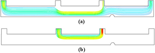
Figure 1. Schematic of microfluidic device (a) perspective view and (b) movement of microparticles in vertical plane.
Pamme and Manz (Citation2004) developed a microfluidic device employing a permanent magnet for separation of magnetic microparticles based on size. With regards to this device, all incoming microparticles are acted up on by magnetophoretic force which deflected the same in the lateral direction, toward the magnet, to exit the microfluidic device through different outlets. Pamme and Manz (Citation2004) used this device to separate a sample consisting of 2 and 4.5 µm magnetic microparticles into two homogenous samples. Nandy et al. (Citation2008) developed an analytical model of a microfluidic device for separation of magnetic microparticles from the incoming microparticle mixture. With regards to this device, magnetic microparticles are attracted and captured on the microchannel’s bottom surface where the highest gradient of the spatially varying magnetic field exits. The model takes into account the forces associated with drag and magnetophoresis. Nandy et al. (Citation2008) studied the influence of geometric and operating parameters on the capture efficiency of the device. Khashan and Furlani (Citation2014) modeled a microfluidic device employing magnetophoresis realized via multiple finite sized soft magnetic elements integrated into the bottom surface of the microchannel; this device works by capturing the magnetic microparticles on the surface of the soft magnetic elements. The model took into account the effect of magnetic force and drag. The authors studied the influence of geometric parameters of the soft magnetic element on the capture efficiency and found that the capture efficiency plateaued after the first few elements. Wu et al. (Citation2017) developed a microfluidic device for separation of nanoparticles, with magnetic properties, based on size. In the first part of the device, all incoming nanoparticles are focused using sheath flow. In the second part of the microfluidic device, the nanoparticles are pulled in the lateral direction by magnetophoretic force associated with a permanent magnet. The large microparticles are deflected further than small microparticles due to the influence of magnetophoretic force on size of microparticles to exit the microfluidic device through different outlets and thereby achieve size-based separation. Samanta et al. (Citation2017) mathematically modeled a continuous flow microfluidic device for separation of microparticles, with magnetic properties, based on size. With regards to this device, the first inlet introduces the sample consisting of three different sized microparticles while introducing a buffer sample through a second inlet and each microparticle is extracted from the device through unique outlets. A dipole located near the outlets is used for creating the required spatially varying magnetic field. The model takes into account forces associated with drag and magnetophoresis. Samanta et al. (Citation2017) used the model to study the influence of geometric parameters on the performance metrics such as separation efficiency and purity; the mixture used for parametric study consists of 2 µm (magnetic), 1 µm (magnetic) and 0.5 µm (diamagnetic) microparticles. Golozar et al. (Citation2017) developed the mathematical model of a magnetophoretic microfluidic device employed for separating magnetically tagged circulating tumor cells from a biological sample. The spatially varying magnetic field is created inside the microchannel using an array of magnets kept in contact. The model takes into account the forces related to magnetophoresis, gravity, buoyancy, and drag. The model is employed for parametric study to assess the influence of magnetic bead size (1, 2.8, and 4.5 µm), cell size (10–30 µm), number of beads per cell (4–20 µm), and flow rate (100–250 mL/h) on the performance of the device.
This article proposes a continuous flow magnetophoretic microfluidic device for separation of microparticles, with magnetic properties, based on size. Unlike microfluidic devices based on capture and release mode for separation of magnetic microparticles, the microfluidic device presented in this article employs continuous mode for separation which allows for continuous size-based separation without suffering from saturation of separation. Other advantages of the proposed microfluidic device are that it is easy to manufacture, as it employs a combination of soft magnetic element and permanent magnet, and it can handle high relatively flow throughput. Moreover, higher throughputs can be achieved by having several proposed devices operate in parallel. The highest throughput processed in magnetophoretic microfluidic device, under experimental conditions, is ca. 0.5 mL/h (Xuan, Citation2019). With the proposed device, it is possible to process much higher throughput than currently possible; this is because the non-uniformity of the magnetic field does not decay along the width of the microchannel and for this reason, the width of the device can be high to handle the desired throughput. The mathematical model presented later in the section of this article is a true dynamic model unlike mathematical models existing in literature. Most models in literature does not account for the inertial force, as it is small for microparticles. However, the use of inertial force allows for determining the distance and time required in the device for achieving sorting as well as the temporal variation of levitation. If the inertial force is not included then only the levitation height under steady-state conditions can be determined and this is only of limited use while designing the device.
This article details a microfluidic device, Figure that employs magnetophoresis for separation of microparticles, based on size, while being suspended in a diamagnetic medium. The device consists of a soft magnetic element which is cylindrical in shape and located at the bottom of the microchannel such that only the top half of the soft magnetic element is exposed to the medium. A uniform external magnetic field is applied perpendicular to the longitudinal axis of the soft magnetic element and this causes the magnetic field near the soft magnetic element to vary. The microfluidic device has two inlets with the first inlet employed for introducing the sample while the second inlet is used for introducing sheath flow that is needed for focusing of the microparticles introduced at the first inlet. All microparticles are focused near the microchannel’s bottom surface before reaching the soft magnetic element. As the magnetic microparticle nears the edge, labelled A, of the soft magnetic element, it experiences repulsive magnetophoretic force which leads to it being repelled toward the top of the microfluidic device. Since the magnetophoretic force is dependent on the radius of the magnetic microparticle, large microparticles are repelled earlier and farther into the upper part of the microchannel than small microparticles. This causes the large microparticle to reach the top surface of the microchannel, before the small microparticle, thereby enabling their extraction from outlet-1. The small microparticles bypass outlet-1, as they do not reach the top surface of the microchannel along with the large microparticles, and they are extracted from outlet-2. Thus, the microfluidic device shown in Figure achieves separation of microparticles, with magnetic properties, based on size.
Mathematical model
The movement of microparticles, with magnetic properties, in the microfluidic device, shown in Figure , can be modeled using Newton’s 2nd law after including the external forces such as magnetic and hydrodynamic forces, Eqs. (1) and (2) (Khashan et al., Citation2014).
(1)
(1)
(2)
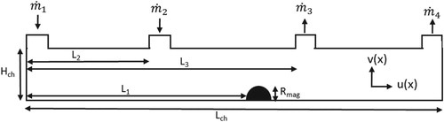
(2) Sedimentation force is neglected, in this study, as the density of microparticles is same as that of the medium (Khashan et al., Citation2014). With regards to the device, microchannel’s width is significantly higher than its height, and therefore, the flow pattern in the microchannel can be assumed to be same throughout the width. This, along with the fact that there is no variation of magnetic force along the width of the microchannel allows for reducing the computational domain to the single vertical plane as shown in Figure .
Figure 2. Schematic of the computational domain of the microfluidic device.
The magnetic force can be calculated using an effective dipole moment method where the microparticle is treated as an equivalent point with a magnetic dipole moment as shown in Equation (3) (Khashan et al., Citation2014).
(3)
(3) The magnetization meff is modeled as shown in Equation (4) while the
(4)
(4) where the function f(Ha) can be written as,
(5)
(5)
where χp is the intrinsic magnetic susceptibility of the particle, χm is the intrinsic magnetic susceptibility of the fluid (suspension medium), and Msp is saturation magnetization. The magnetic susceptibility of the microparticles is where Hin is the magnetic field inside the particle. The magnetic field, Hin, inside the microparticle depends on Ha, and is given as
where Nd is the microparticle demagnetization factor (Khashan et al., Citation2014). In addition,
where
is the apparent susceptibility. The microparticle susceptibility is given as
(6)
(6) The typical value of
for spherical microparticles is
. Thus, for a spherical microparticle, the above equation reduces to
. Equation (1) can appropriately be revised as
(7)
(7) The magnetic permeability of free space is µo = 1.257 × 10⁻⁶ N/A2. The components of the magnetic field He for a long rectangular element of width, W = 2w, and magnetized to saturation Mes by a bias field Hbias in the vertical y-direction can be expressed in a similar method given as (Khashan et al., Citation2014),
(8)
(8) and
(9)
(9) The magnetic force components for a single element are given as (Lee et al., Citation2016):
(10)
(10)
(11)
(11) In the current study, the carrier fluid is nonmagnetic, i.e.
, while the saturation magnetization
and an initial (low field) apparent susceptibility
are taken to be 4.3 × 10⁴ A/m and 1.4, respectively (Khashan et al., Citation2014). A uniform bias field
of 3.9 × 10⁻⁵ A/m (0.5 Tesla) is applied upward, perpendicular to the base of the channel (Khashan et al., Citation2014). The soft magnetic element is assumed to be made from permalloy (78% Ni and 22% Fe) with saturation magnetization
of 8.6 × 10⁵ A/m (Khashan et al., Citation2014).
The initial conditions associated with Equation (7) include the initial displacements and initial velocities. The initial displacement along the x-direction is same as the x-coordinate of the inlet. The microparticle can assume any position at the inlet of the microchannel and this subsequently determines the initial y-displacement. The initial velocities are same as the fluid velocity at the initial position of the microparticle. The fluid velocity required for solving Equation (6) is obtained by solving the Navier-Stokes equations inside the microchannel. The boundary conditions associated with the Navier-Stokes equations include the velocities at the inlets and pressure at the outlet. The solution procedure starts by solving the Navier-Stokes equations inside the microchannel to obtain the steady-state fluid velocity inside the same. This is followed by solving Equations (2) and (7) to obtain the trajectory of the microparticles.
Microparticles of two different sizes, i.e. Rp = 1 and 10 µm, are used in this study to examine the performance metrics of the device. The width of all inlets and outlets are set to be equal to 0.5 mm. Other dimensions that are kept constant include: Re = 0.2 mm, Lch = 14 mm, L1 = 10 mm, L2 = 5 mm. In addition, the externally applied magnetic strength is kept constant as .
The performance metrics associated with microfluidic devices used for separation include purity, separation efficiency, and concentration ratio. The purity of the outlet stream is given as,
(12)
(12) The separation efficiency
is defined as,
(13)
(13) and the concentration ratio
is defined as,
(14)
(14) The performance metric includes purity, separation efficiency and concentration ratio (number of particles multiplied by the velocity at a given outlet compared to the number of particles multiplied by the velocity at the inlet). This concentration ratio can increase to more than 100%, and this is the goal of the microfludic separation device which is to increase concentration of particles at one outlet compared to the inlet. However, the purity and separation efficiency can vary from 0% to 100%.
A comprehensive study to examine the best operating conditions is conducted to examine the different influencing design and operating conditions, including microchannel height (Hch), fluid velocity in channel , outlet-1 location (L3), ratio of inlet flow rates
, and ratio of outlet flow rates
. The displacement of the microparticle can be determined only if the velocity of the fluid is available. The fluid flow behavior in the microchannel is dictated by the continuity equation and Navier-Stokes equations as provided below (Ghalandari et al., Citation2019).
(15)
(15)
(16)
(16)
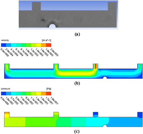
The calculations are performed using the CFD software ANSYS Fluent (v15.0). The continuity and momentum equation given Equations (15) and (16) are solved numerically by finite volume method code in ANSYS Fluent. CAD model for the fluid domain in the microchannel is created. The CAD model is then meshed as shown in Figure (a), which consists of 6740 nodes and 6394 elements. A fine mesh is used to correctly capture the gradients associated with all phenomena existing in the microchannel (Akbarian et al., Citation2018; Mosavi et al., Citation2019). The mesh method used is advanced size function curvature. The discrete phase model (DPM) is activated and used to solve the movements of particles in the microchannel in Equations (1) and (2). A user defined function (UDF) code is written to solve for the magnetic field distribution and the magnetic forces given in Equations (3–11). The coupling between pressure and velocity for solving the momentum equation is done by SIMPLE algorithm and the gradient is discretized using Least Square Cell-Based scheme. The pressure term is discretized using second order interpolation scheme. The momentum equation is discretized using second order upwind scheme. The simulation run time is 5 min.
Figure 3. Schematic of (a) part of the discretized computational domain, (b) velocity distribution in computational domain, and (c) pressure distribution in computational domain (Hch = 1 mm, L3 = 9 mm, vch = 1 mm/s, ,
, Hbias = 0.5 Tesla).
Results and discussions
Figure (a) shows the discretized computational domain, and Figure (b) and (c) show the velocity and pressure distribution, respectively, in microfluidic device. It is clearly shown that there is an increased velocity in the channel near inlet-2 due to the introduction of sheath flow. It is also noted that there is an increase in velocity near the soft magnetic element which is due to the reduction in the cross-sectional area of microchannel. It is also to be noted that the fluid velocity at outlet-1 is more than that in outlet-2 indicating that the flow rate is not the same in the outlets. Reynolds number is not specified for the study as the computation is two-dimensional.
Figure shows the trajectory of the microparticles in the microchannel. It is shown that the microparticles enters from inlet-1 and while moving in the microchannel they get pushed downwards by the sheath flow introduced from inlet-2; it is essential to push the microparticles near to the soft magnetic element for proper functioning of the microfluidic device. As the microparticles near the soft magnetic element, they experience magnetophoresis; the magnitude and direction of the associated force depends on the positions of the microparticle in the flow. Due to magnetophoresis, the microparticles initially get pushed in the positive y-direction which leads them toward outlet-1. It is shown that all large microparticles (10 µm) exits through outlet-1, and small particles (1 µm) exit from both outlets. It is to be noted that large microparticles are affected more significantly, by the spatially varying magnetic field, than small microparticles and this is clearly shown in Figure as these large microparticles change direction earlier than the small microparticles. The reason for this is the dependence of magnetic force on volume of the microparticle. Figure (a) and (b) show the distribution of streamlines in the microfluidic device. It is evident from Figure (a) that all of the fluid entering the inlet-2 leaves through outlet-1 and a small amount of fluid entering inlet-2 leaves through outlet-1. On the other hand, most of the fluid entering inlet-1 leaves through outlet-2 as can be observed from Figure (b).
Figure 4. Particles separation in microfludidic device (Hch = 1 mm, L3 = 9 mm, vch = 1 mm/s, ,
, Hbias = 0.5 Tesla;
![]()
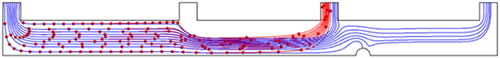
Figure 5. Streamlines in the microfludidic sorting device (a) sample, (b) sheath flow (Hch = 1 mm, L3 = 9 mm, vch = 1, ,
).
Various geometric and operating parameters influence the movement of microparticles inside the microchannel and their separation efficiency. The parameters include channel height (Hch), outlet-1 location (L3), fluid velocity in channel (vch), ratio of inlet flow rates , ration of outlet flow rates
, and magnetic field strength. Figure shows the trajectory of microparticles for different outlet-1 locations. It is shown in Figure (a) that moving the outlet-1 location backward (L3 = 8 mm) leads to inefficient separation because fewer large particles are exiting through outlet-1. It is also shown in Figure (c) that moving the outlet-1 location forward (L3 = 10 mm) leads to inefficient sorting; all large particles (10 µm) will be captured by the magnet and they do not leave the microchannel. Thus, there is an optimum position of outlet-1 that maximizes the separation. As shown in Figure , large microparticles are more affected by the magnetic field than small microparticles because of their larger volume. It is also shown in Figure (c) that large microparticles initially moves upward toward outlet-1; however, as they get close to the magnetic structure, they get attracted toward the magnet. This leads to all large particles being captured by the magnet while resisting the hydrodynamic force that moves them toward outlet-1. This is due to the fact that the magnetic force for all large particles is high compared to small particles, and the magnetic force is larger than the drag force of the moving fluid. This causes the large particles to be pulled near the magnet surface at the bottom of the channel and get attached to the surface. Figure shows the performance metrics (purity, separation efficiency, and concentration ratio) associated with large microparticles for different L3. It is shown that the efficiencies are maximized for a specific location for outlet-1. As shown, the performance metric which include the separation efficiency and concentration ratio efficiency (or number of particles) at outlet 1 increased by a certain value compared to the concentration (or number of particles) at the inlet.
Figure 6. Microparticles’ separation in microfluidic device for different outlet-1 locations (a) L3 = 8 mm, (b) L3 = 9 mm 1.5, (c) L3 = 10 mm, (Hch = 1 mm, vch = 1 mm/s, ,
Hbias = 0.5 Tesla;
![]()
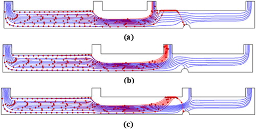
Figure 7. Peroformance metrics for varying outlet location L3.
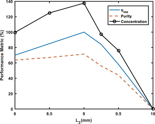
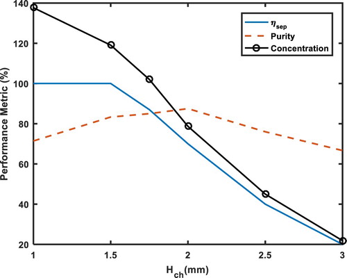
Figure shows the trajectory of microparticles for different microchannel heights. It can be observed that the microchannel height affects the trajectory and in turn the performance metrics. It is evident that increasing the microchannel height leads to increasing the levitation height in the y-direction that the large microparticles have to travel to reach outlet-1. This results in some large microparticles reaching the x-position of outlet-1 (L3 = 8 mm), but their y-position is away from outlet-1. As a result, some large microparticles will be either attracted toward the magnet or leave through outlet-2. It is observable from Figure (d) that few microparticles (large and small) will be attracted and captured by the magnet, while the remaining will exit through the outlets. Figure shows the variation of performance metrics with different microchannel heights. It is shown that the separation efficiency is maximum when microchannel height is small. With increase in microchannel height, the distance that needs to be traveled in the y-direction to exit through outlet-1 increases thereby leading to reduction in separation efficiency. Regarding purity, it is noted that there is an optimum microchannel height for which the purity is maximum. At intermediate heights, the purity suffers due to the increased number of small microparticles escaping with the large particles through outlet-1. At higher heights, the number of large microparticles exiting through outlet-1 are few, and as a result the purity decreases. The purity is maximum at microchannel height of 2 mm. Figure shows outlet to inlet concentration ratio of large particles for different microchannel heights. It is shown that the concentration ratio decreases as microchannel height decreases.
Figure 8. Microparticles’ separation in microfluidic device for different (a) Hch = 1 mm, (b) Hch = 1.5 mm, (c) Hch = 2 mm, (d) Hch = 3 mm (L3 = 9 mm, vch = 1 mm/s,,
, Hbias = 0.5 Tesla;
![]()
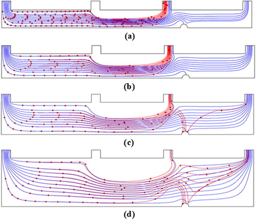
Figure 9. Peroformance metrics for different channel thickness Hch.
The trajectory of microparticles for different ratio of inlet flow rates are provided in Figure . It is clearly evident from Figure that the ratio of inlet flow rates influences the separation efficiency; decreasing the ration inlet flow rates leads to more efficient separation. Reducing the ratio of inlet flow rates increases the hydrodynamic force exerted on the microparticles by the fluid from outlet-2 which lead to them being focused closer to the bottom surface of the microchannel. As a result, once the microparticles reaches the spatially varying magnetic field, they get pushed by the magnetic forces upward and continue to flow to exit at outlet-1. It is noticed that decreasing the ratio of inlet flow rates results in more precise separation as shown Figure (d). Figure shows the purity, separation efficiency, and concentration ratio of large microparticles for different ratio of inlet flow rates. It is shown that the separation efficiency is almost independent of ratio of inlet flow rates. However, it is noted that increasing ratio of inlet flow rates decreases the purity. Figure shows outlet to inlet concentration ratio of large microparticles for different ratio of inlet flow rates. It is shown that the concentration ratio decreases with increase in as the ratio of inlet flow rates.
Figure 10. Microparticles’ separation in microfluidic device for different inlet flow rate ratio (a) , (b)
, (c)
, (d)
(L3 = 9 mm, vch = 1 mm/s,
, Hbias = 0.5 Tesla;
![]()
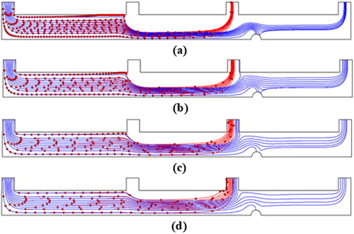
Figure 11. Peroformance metrics for different inlet flow ratio m1/m2.
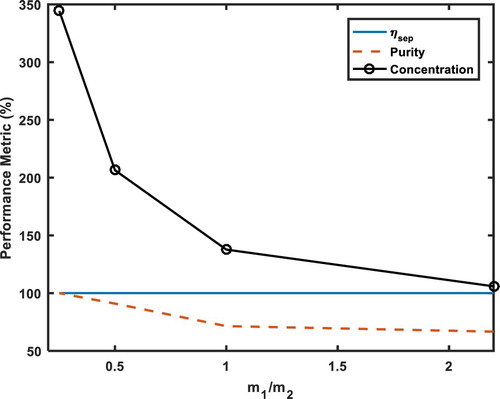
Figure shows the distribution of the tracks of microparticles for different ratios of outlet flow rates. It is observed that the ratio of outlet flows ratio plays an important role on the separation efficiency; increasing ratio of outlet flow rates leads to improvement in separation. Reducing the outlet flow rates reduces that the flow rate exiting outlet-2 which leads to reduction in the hydrodynamic force pushing microparticles upward toward outlet-2. This has a more pronounced effect on small microparticles compared to large microparticles due to which the number of small microparticles reaching outlet-2 is reduced as the ratio of outlet flow rates is reduced. Figure shows the purity, separation efficiency, and concentration ratio of large microparticles for different ratio of outlet flow rates. It is shown that the separation efficiency is remains almost constant for all ratios of inlet flow rates. It is noted that with increasing ratios of outlet flow rates the purity decreases. Figure also shows concentration ratio of large microparticles for different ratios of outlet flow rates; it is observed that concentration ratio increases with increase in ratio of inlet flow rates. Figure provide a method to examine the best operating condition in regard to the different performance metrics for different outlet flow ratio. As shown in Figure , the purity decreases with increasing the mass flow rate of outlet 3 to outlet 4 ratio, however the concentration increases with increasing mass flow rate of outlet 3 to outlet 4 ratio. Therefore, the outlet flow ratio can be controlled to achieve the desired operating condition.
Figure 12. Microparticles’ separation in microfluidic device for different outlet flow rate ratio (a) , (b)
, (c)
(L3 = 9 mm, vch = 1 mm/s,
, Hbias = 0.5 Tesla;
![]()
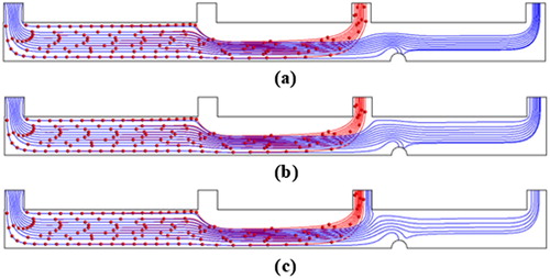
Figure 13. Peroformance metrics for different outlet flow ratio m3/m4.
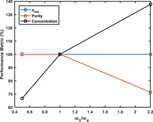
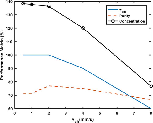
Figure shows the distribution of trajectory of microparticles for different fluid velocities. It is very evident that fluid velocity in the channel influences the separation efficiency. It is shown in Figure that increasing fluid velocity translates to faster movement of fluid and the magnetic microparticles in the axial direction. As fluid moves in the axial direction faster, the time of travel in the y-direction is shortened. It is observed that increasing the flow velocity reduces the number of 1 and 10 µm microparticles exiting through outlet-1. This leads to the large microparticles which did not exit through outlet-1 to be captured by the soft magnetic element. As shown in Figure , larger microparticles are more affected by the magnetic field and attracted more than small microparticles because of their larger volume. As a result, the large microparticles moves in the y-direction faster than small microparticles. Also, with increased velocity, large microparticles which did not exit from outlet-1 will be captured by the soft magnetic element. Figure shows variation of performance metrics associated with large microparticles for different fluid velocities. It is shown that the separation efficiency decreases when fluid velocity increases. It is noted that there is an optimum fluid velocity for which the purity is maximum; however, the variation of purity with fluid velocity is negligible. Figure shows concentration ratio of large microparticles for different fluid velocities; concentration ratio decreases as fluid velocity increases.
Figure 14. Microparticles’ separation in microfluidic device for different fluid velocities (a) vch = 0.5 mm/s, (b) vch = 1 mm/s, (c) vch = 2 mm/s, (d) vch = 4 mm/s, (e) vch = 8 mm/s (L3 = 9 mm, ,
, Hbias = 0.5 Tesla;
![]()
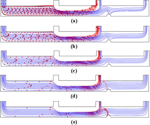
Figure 15. Peroformance metrics for different channel velocities vch.
The parametric study provides in depth knowledge of the influence of each geometric and operating parameters on the performance metrics. The designers can use the model presented for making decision on selecting the operating and geometric parameters of the proposed microfluidic device for achieving the desired level of achievement of the performance metrics.
Conclusions
A continuous flow magnetophoretic microfluidic device for separation of microparticles with magnetic properties, based on size, is presented in this document. Mathematical model of the microfluidic device is developed to assess the relationship of operating and geometric parameters on its working. The model reveals that good performance metrics can be obtained by appropriately choosing the geometric and operating parameters. The mathematical model is specifically useful for designers in choosing the parameters, i.e. both geometric and operating, of the conceptualized magnetophoretic microfluidic device with the best performance metrics. It is stressed here that this model is applicable only when handling dilute suspensions as well as when the width of the device is much larger than its height. Future work would include advancing the model to handle dense suspensions.
Nomenclature
| A | = | area (m2) |
| CA | = | concentration ratio (%) |
| F | = | force (N) |
| H | = | magnetic field (Tesla) |
| h | = | height (m or mm) |
| L | = | length (m or mm) |
| m | = | mass (kg) |
| = | mass flow rate (kg/s) | |
| n | = | number of microparticles |
| P | = | purity (%) |
| R | = | radius (m or mm) |
| u | = | velocity vector (m/s) |
| V | = | volume (m3) |
| S | = | separation efficiency (%) |
| w | = | width (m or mm) |
Greek Alphabets
| η | = | medium viscosity (Pa.s) |
| µ | = | magnetic permeability |
| = | susceptibility |
Subscript
| a | = | apparent |
| ch | = | channel |
| e | = | element |
| eff | = | effective |
| Mag | = | magnetophoresis |
| m | = | medium |
| p | = | microparticle |
| 1 | = | first inlet or first outlet |
| 2 | = | second inlet or second outlet |
Acknowledgment
The authors acknowledge the financial support received from the National Water Center (NWC) and the United Arab Emirates University for Grant no. 31R153, and from Abu Dhabi Department of Education and Knowledge (ADEK) in UAE for Grant no. 21N220-AARE18-089.
Disclosure statement
No potential conflict of interest was reported by the author(s).
Additional information
Funding
References
- Akbarian, E., Najafi, B., Jafari, M., Ardabili, S. F., Shamshirband, S., & Chau, K. W. (2018). Experimental and computational fluid dynamics-based numerical simulation of using natural gas in a dual-fueled diesel engine. Engineering Applications of Computational Fluid Mechanics, 12(1), 517–534. https://doi.org/10.1080/19942060.2018.1472670
- Alnaimat, F., Dawgher, S., Mathew, B., Hilal-Alnaqbi, A., & Khashan, S. (2018). Microfluidics based magnetophoresis: A review. The Chemical Record, 18(11), 1596–1612. https://doi.org/10.1002/tcr.201800018
- Ghalandari, M., Koohshahi, E. M., Mohmadian, F., Shamshirband, S., & Chau, K. W. (2019). Numerical simulation of nanofluid flow inside a root canal. Engineering Applications of Computational Fluid Mechanics, 13(1), 254–264. https://doi.org/10.1080/19942060.2019.1578696
- Golozar, M., Molki, M., & Darabi, J. (2017). Computational and performance analysis of a continuous magnetophoretic bioseparation chip with alternating magnetic fields. Microfluidics and Nanofluidics., 21(4), art. no. 73. https://doi.org/10.1007/s10404-017-1909-4
- Khashan, S. A., Alazzam, A., & Furlani, E. P. (2014). Computational analysis of enhanced magnetic bioseparation in microfluidic systems with flow-invasive magnetic elements. Scientific Report, 4, art. no. 5299. https://doi.org/10.1038/srep05299
- Khashan, S. A., & Furlani, E. (2014). Scalability analysis of magnetic bead separation in a microchannel with an array of soft magnetic elements in a uniform magnetic field. Separation and Purification Technology., 125, 311–318. https://doi.org/10.1016/j.seppur.2014.02.007
- Lee, G. H., Kim, S. H., Ahn, K., Lee, S. H., & Park, J. Y. (2016). Separation and sorting of cells in microsystems using physical principles. Journal of Micromechanics and Microengineering, 26, art. no. 013003. https://doi.org/10.1088/0960-1317/26/1/013003
- Mark, D., Haeberle, S., Roth, G., von Stetten, F., & Zengerle, R. (2010). Microfluidic lab-on-a-chip platforms: Requirements, characteristics and applications. Chemical Society Reviews., 39(3), 1153–1182. https://doi.org/10.1039/b820557b
- Mathew, B., & Weiss, L. (2015). MEMS heat exchangers. In A. Tiwari & B. Raj (Eds.), Materials and failures in MEMS and NEMS (pp. 63–120). Wiley. https://doi.org/10.1002/9781119083887.ch3
- Mosavi, A., Shamshirband, S., Salwan, E., Chau, K. W., & Tah, J. H. M. (2019). Prediction of multi-inputs bubble column reactor using a novel hybrid model of computational fluid dynamics and machine learning. Engineering Applications of Computational Fluid Mechanics, 13(1), 482–492. https://doi.org/10.1080/19942060.2019.1613448
- Nandy, K., Chaudhuri, S., Ganguly, R., & Puri, I. K. (2008). Analytical model for the magnetophoretic capture of magnetic microspheres in microfluidic devices. Journal of Magnetism and Magnetic Materials., 320(7), 1398–1405. https://doi.org/10.1016/j.jmmm.2007.11.024
- Pamme, N., & Manz, A. (2004). On-Chip free-flow magnetophoresis: Continuous flow separation of magnetic particles and Agglomerates. Analytical Chemistry., 76(24), 7250–7256. https://doi.org/10.1021/ac049183o
- Samanta, A., Ganguly, R., Datta, A., & Modak, N. (2017). Separation of magnetic beads in a hybrid continuous flow microfluidic device. Journal of Magnetism and Magnetic Materials., 427, 300–305. https://doi.org/10.1016/j.jmmm.2016.10.143
- Wu, J., Yan, Q., Xuan, S., & Gong, X. (2017). Size-selective separation of magnetic nanospheres in a microfluidic device. Microfluidics and Nanofluidics, 21, art. no. 47. https://doi.org/10.1007/s10404-017-1886-7
- Xuan, X. (2019). Recent advances in continuous-flow particle manipulations using magnetic fluids. Micromachines, 10(11), art. no. 744. https://doi.org/10.3390/mi10110744