
 ?Mathematical formulae have been encoded as MathML and are displayed in this HTML version using MathJax in order to improve their display. Uncheck the box to turn MathJax off. This feature requires Javascript. Click on a formula to zoom.
Abstract
In a boundary layer ingestion (BLI) propulsion system, the compressor rotor operates under the condition of a severe inflow distortion because the boundary layers on the surface of aircraft have been ingested. In this situation, the low-momentum fluid would inevitably raise the blade load and aggravate the local aerodynamic losses, thus severely deteriorating the compressor overall aerodynamic performance. The paper has applied a sweep optimization design based on surrogate model and genetic algorithm to a transonic axial-flow compressor at the condition of total pressure distorted inflow. The optimization objective is to improve the compressor efficiency. The sweep design has been implemented through controlling the shape of the blade stacking line and the time-saving steady numerical simulations are mainly utilized in the optimization process. Then, the full-annulus unsteady CFD calculations have been conducted for validating the optimized design and further analyzing the flow mechanisms of performance improvements. The computational results show that the inflow distortion has led to non-uniform distributions of the tip leakage loss and the hub flow separation loss along the circumferential direction. It is found that the rotor blade has suffered from the highest tip leakage losses and hub separation losses during the blade leaving the distorted region. After rotor sweep optimization, both tip leakage and hub separation losses have been notably reduced along the full circumferential direction. Moreover, for different pitchwise locations, the optimized rotor sweep design has achieved more aerodynamic performance improvements in the process of the rotor blade leaving the distorted region than those in the processes of the rotor blade moving out of, moving towards and entering the distorted region. Overall, the optimized design performs better than the baseline design in terms of adiabatic efficiency in the entire operating range. In the meanwhile, the total pressure ratio has been maintained. Specifically, an approximately 0.5% increment of efficiency has been achieved by the optimized design at the optimization point. For this paper, the major purpose is to offer useful guidelines for fan/compressor design strategy to achieve high aerodynamic performances under distorted inflow working condition.
1. Introduction
Currently, the compression systems in both the military and civil aero-engines are subjected to inflow distortions due to off-design working conditions (like inlet separations) or particular flight conditions (like landing, taking off and maneuvering). Compared with clean inflow operating conditions, the inflow distortions have severe impacts on the stagnation pressure ratio, adiabatic efficiency and stall margin of a fan/compressor (Cousins et al., Citation2003; Longley & Greitzer, Citation1992; Williams, Citation1987). Up to now, the investigations concerning the inlet distortions in fan/compressors are still drawing much attention.
Among different types of inlet distortions, the total pressure distortion is one of the most common forms and has significant influences on the aerodynamic performances of compressors, thus attracting much more attentions from researchers (Kennedy et al., Citation2014; Liu et al., Citation2018; Triantafyllou et al., Citation2018). In the past decades, much research work has been focused on two aspects: one is the efficient computational approaches to analyze the effects of inflow distortions; the other is the numerical and experimental studies concerning influences of distorted inflows on the compressor inner flow fields and overall aerodynamic performances.
With respect to the computational techniques concerning the effects of inflow distortions, several methods have been developed and they are still widely used nowadays. These computational techniques include parallel compressor theory (Mazzawy, Citation1977; Pearson & McKenzie, Citation1959), actuator disks (Hawthorne et al., Citation1978; Horlock, Citation1979), simple semi-empirical methods (Valencia et al., Citation2017), through-flow analysis (Hall et al., Citation2017) and body force methods (Guo & Hu, Citation2018; Thollet et al., Citation2016). Although these methodologies can get the features of non-uniform inflow redistributions across the rotor through low computational cost, many flow details such as the secondary flows in compressors can’t be well and fully captured due to the corresponding assumptions and simplifications.
With the CFD techniques developing rapidly in the recent two decades, the three-dimensional (3-D) unsteady CFD methods or the combination of the CFD and experiments have been extensively applied to investigate the influences of distorted inflows on the inner flows in compressors. Hah et al. (Citation1996) investigated the inner flow fields in the rotor blade passage of a transonic compressor under circumferential total pressure inflow distortions. They noted that the passage shock presented unsteady characteristics and interacted intensively with the boundary layers. This interaction aggravated flow blockages and led to increased losses and a reduced stable operating range. Fidalgo et al. (Citation2012) conducted computational studies to understand the interaction between total pressure distorted inflows and a transonic fan. The results showed that swirling flows and mass flow redistributions were induced by the distorted inflow and seriously affected the local operating condition and work input of the fan. At the same time, a variation of shock wave structure in the rotor passage was also observed. Sun et al. (Citation2013) investigated the effects of total pressure inflow distortions on the end-wall flows in a single-stage compressor. They reported the inflow distortions showed significant influences on the structure, position and intensity of shock wave near the casing. Furthermore, Florea et al. (Citation2013) noted that a combination of a distortion tolerated fan stage and a well-performed inlet duct presented a significant potential for the aerodynamic benefit achievements of a boundary layer ingestion propulsion system. In the meanwhile, the results also suggested that the stator blades were operating at a cruise inflow condition. Gunn and Hall (Citation2014) also carried out an investigation on the BLI fan aerodynamics because the fan continuously worked at the inlet total pressure distortion condition. The results showed circumferentially and radially non-uniform flow structures can be notably observed in rotor and stator blade passages, leading to serious flow losses. From the above research, it can be found that the distorted inlet total pressure condition significantly influences the fan/compressor inner flow fields and aerodynamic performances.
Specifically, the inlet total pressure distortion would be alleviated after it passes through the rotor blade. The interaction between the rotor and the distorted inflow would in turn affect the upstream static pressure field, which causes mass flow and swirl redistributions upstream the rotor. In this situation, the variation of the blade load can be also observed and would severely lead to aerodynamic losses in the blade passage. An effective fan/compressor design strategy which can tolerate inlet total pressure distortion has become a challenging topic. Therefore, it is very essential to reduce the impacts of the total pressure distorted inflows on compressor aerodynamic performances.
To reduce the negative impacts of the distorted inflow on the fan/compressor aerodynamic performance, some investigations on decreasing the losses in compressors have been attempted. Shaw et al. (Citation2014) made a numerical investigation on a transonic fan working at the condition of inflow distortions and focused on the effect of variable inlet guide vane (VIGV) on fan aerodynamic loss and stall margin. The results indicated the VIGV could improve the overall aerodynamic performances of the fan through decreasing the swirls at the inlet of the rotor blade. Furthermore, Sun et al. (Citation2019) attempted to apply a non-axisymmetric stator design to a transonic compressor to reduce the negative impacts of circumferential total pressure distortion, and the results validated its effectiveness.
In the scope of the open literature concerning the fan/compressor inlet total pressure distortion problem, the research on the stator blade design has been presented to eliminate the impacts of distorted inflows on the compressor performances. There are still few reports concerning the design and optimization for the fan/compressor rotor. However, the inlet total pressure distortion would lead to a load redistribution in the blade passage and have significant influences on tip leakage loss, shock loss and hub separation loss. Previously, it has been reported that the 3-D blade re-designs show positive effects on reducing the compressor aerodynamic losses under clean inflow conditions (Mohsen et al., Citation2017; Venturelli & Benini, Citation2016). Among these designs, the blade sweep design could be beneficial to enhance the aerodynamic performances of transonic compressors (Biollo & Benini, Citation2009; Cui et al., Citation2016; Hah et al., Citation1998). Therefore, a sweep optimization design has been attempted in the present work to further explore an effective rotor blade design strategy to mitigate the impacts of inlet total pressure distortion.
For transonic compressors working under total pressure inflow distortions, the rotor blade would periodically pass through the distorted and undistorted regions. The low-momentum fluids induced by the distorted region would increase the blade loads at the end-wall regions and aggravate the local aerodynamic losses. To advance the compressor design to tolerate inflow distortions, this paper has conducted a sweep optimization design in a transonic compressor rotor by controlling the shape of blade stacking line based on an integrated optimization design procedure. Then, the 3-D full-annulus unsteady CFD calculations have been implemented to analyze inner flows for the optimized rotor design and further reveal flow mechanisms for the performance improvements. The motivation of this work is to give some practical guidelines for rotor sweep design to tolerate the inlet total pressure distortion and in the meanwhile enhance the fan/compressor aerodynamic performances.
2. Study case and numerical methods
2.1. Study case
As a widely and fully reported test case, the NASA Rotor 67, which is a high-performance low-aspect ratio transonic fan, has been selected as the baseline rotor in this work. This transonic axial-flow fan rotor is regarded as the first-stage rotor of a two-stage fan. The solidity of the rotor is 3.11 in the hub end and 1.29 in the tip end. The hub-to-tip ratio is 0.375 at the inlet and 0.478 at the outlet. Table summarizes the other main design parameters of the NASA Rotor 67 (Strazisar et al., Citation1989).
Table 1. Design values of parameters for NASA Rotor 67.
2.2. Numerical methods
The compressor inner flow fields and aerodynamic performance are achieved based on solving the 3-D compressible Reynolds-averaged Navier-Stokes equations through a finite volume method. The commercial software NUMECA FINE-Turbo EURANUS has been utilized as the flow solver. Specifically, an explicit fourth-order Runge–Kutta scheme is employed for temporal discretization, while the second-order central-differencing scheme is utilized for spatial discretization. The Spalart-Allmaras turbulence model has been used in this work due to its successful applications and good performances in fluid machines (Elfarra, Citation2019; Lu et al., Citation2019; Suarez et al., Citation2018; Zhao et al., Citation2018).
To take the influences of inlet distortions into account, a 3-D full-annulus computational model has been considered in this study. Figure depicts the whole computational domain. The inlet plane is located at about 2.5 times mid-span axial chord upstream the rotor leading edge, and the location of outlet plane is at 3.5 times axial chord (about 1.5 times rotor blade height) downstream the rotor trailing edge. With regard to boundary conditions, the total temperature and total pressure are imposed at the inlet plane, and the inflow angle is also specified. For the outlet plane, the average static pressure is given which satisfies radial equilibrium equations. The working fluid selects the perfect gas and all the solid surfaces are supposed as no-slip and adiabatic.
Figure 1 The computational model of the transonic axial-flow compressor.
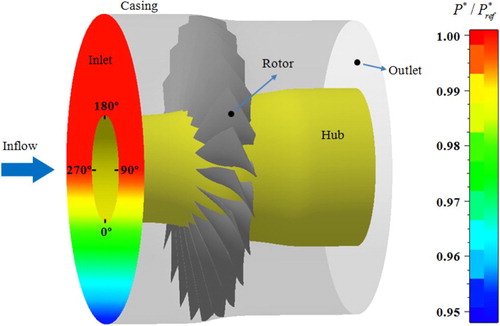
In this study, the profile of total pressure on the inlet plane has also been described in Figure . The rotor blade suffers an about 120 degree total pressure inflow distortion. The intensity of distortion is as follows:
(1)
(1) where
and
represent the maximum and minimum total pressures on the inlet plane. At the same time, the distortion intensity is calculated and equal to about 6% in this work.
In the optimization design process, since a certain number of sampling points (simulation cases) are required and correspondingly a large amount of computational time consumption would be needed, 3-D full-annulus steady CFD calculations have been implemented to predict the compressor performance so as to reduce the overall computational cost. Specifically, the inlet total pressure distortion is made to rotate with the rotor. In this situation, the unsteady effects of the rotor blade entering and leaving the distorted region on the compressor overall aerodynamic performance have been neglected in this process.
After the optimized rotor design has been obtained, 3-D full-annulus unsteady CFD calculations are conducted for validating the optimized design and making full analyses of the inner flow fields. For the unsteady simulations, a dual time stepping technique is utilized in temporal discretization. Specifically, 30 angular positions are selected and in this situation one blade will need 30 time steps to go through a blade pitch. In this process, 20 pseudo-time iterations are required in one time step. Since the rotor has 22 blades, the full-annulus computational model would totally take 660 physical time steps.
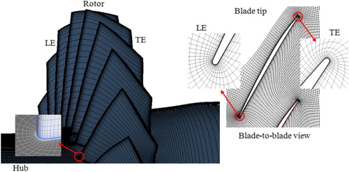
For the computational grid, a structured mesh with O4H topology is used for the whole computational domain, and O-type meshes surround solid surfaces and H-type meshes are filled in the rest zones. The computational meshes for the investigated transonic rotor are described in Figure . In the numerical calculations, the values of the y+ are kept less than 5. To reduce the influences of grid topology on the flow-field solutions, a mesh template is utilized to generate the computational grids of both the re-designs and baseline design to preserve the grid number and topology.
Figure 2. Computational meshes for the investigated compressor.
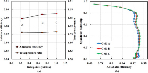
The grid independent investigation has been implemented for reducing the impact of grid number to numerical results. A computational model which includes a single blade passage has been used. In the meanwhile, a total number of three grid sizes are considered here and boundary conditions are imposed identically on the computational domain. As depicted in Figure (a), both adiabatic efficiency and total pressure ratio would have only slight variations when the mesh size changes from Grid B to Grid C compared with when the mesh size varies from Grid A to Grid B. In addition, the rotor efficiency along the spanwise locations has also been compared in Figure (b). The results show the computed rotor efficiency of Grid B shows a good agreement with that of Grid C in whole spanwise locations, both presenting notable differences from that of Grid A mainly from the hub to 90% spanwise location. Taking both the computational time and accuracy into account, the Grid B which contains about 0.7 million grid nodes in a single blade passage has been employed to carry out the CFD simulations, and in this situation approximately 15 million grid nodes have been used for the full-annulus calculations to give predictions of the inner flows in the compressor rotor.
Figure 3. Results of grid independence study (a) Variations of aerodynamic performance parameters and (b) Adiabatic efficiency along spanwise location.
2.3. CFD validations
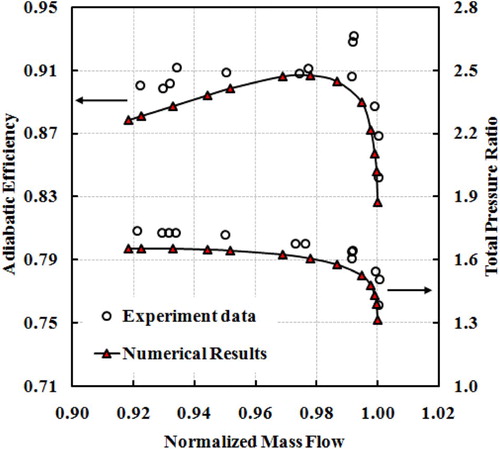
To evaluate the computational methods and tools, the numerical simulation results have been validated using the available experiment results (Strazisar et al., Citation1989). The experiment data based on laser anemometer measurements were obtained at the clean inflow working conditions. Figure compares the rotor aerodynamic performances of the numerical results and the experiment data. The total pressure ratio and adiabatic efficiency are computed using the aerodynamic parameters extracted from the same measuring locations as in the experiment. It can be noted that the predictions given by the adopted computational tool are slight lower than the experiment data at near stall working conditions in terms of adiabatic efficiency and total pressure ratio. Overall, they have a good agreement in the entire operating range.
Figure 4. Comparisons of compressor performance maps of numerical results and experiment data.
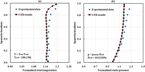
Furthermore, to evaluate the flow details in the transonic compressor, the static pressure and total temperature distributions along the spanwise locations downstream the trailing edge are compared between the CFD and experiment results at near peak efficiency point as shown in Figure . The total temperature is normalized by the inlet total temperature (288.15 K) and the static pressure is normalized by the inlet total pressure (101325 Pa). For the total temperature in Figure (a), the CFD predictions agree well with the experiment data except for some slight deviations in the tip region. For the static pressure in Figure (b), the CFD result agrees well with the experiment data from the hub to about 80% span, while there are slight deviations between the CFD predictions and the experiment results in the tip region. The reason for the deviations between CFD results and experimental data near the blade tip is probably that the secondary flows in this region are very complicated and will not be exactly captured. Overall, the plots of the total temperature and static pressure radial distributions present a good agreement between the CFD and experiment results.
Figure 5. Comparisons of the total temperature and static pressure distributions along the spanwise direction between the CFD results and the experiment data.
On the basis of the above comparisons, it can be indicated that the numerical methods and tools employed in the present work could give reliable performance map evaluations and inner flow-field predictions in the transonic compressor rotor.
3. Problem descriptions
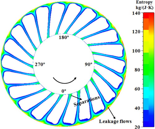
For a fan/compressor rotor operating at the condition of inflow distortions, the blade would periodically travel across the distorted region and the undistorted region. As the rotor blade is immersed in the distorted region, the inflow distortion condition will raise the blade loads and therefore have serious impacts on the flow losses in the tip region, and in the meanwhile flow separations might also occur at the blade hub region. It would aggravate the overall aerodynamic performances of a compressor rotor. Figure gives a plot of the entropy contours at the rotor outlet just downstream the blade trailing edge. It can be found that the intensities of the tip leakage flows and the hub flow separations have presented non-uniform distributions along the circumferential direction in this study. More serious leakage loss and hub separation loss are observed mainly from the 0° to 90° circumferential locations. In this situation, a design strategy which can mitigate the tip leakage losses and hub separation losses would be beneficial for decreasing the overall flow loss and enhancing aerodynamic performances of the compressor.
Figure 6. Contours of the entropy at outlet of the rotor (view along streamwise direction).
For a transonic compressor rotor, the flows in the hub and tip regions are vulnerable to the deteriorated inlet working condition. To eliminate the negative impacts caused by the inflow distortion, a sweep optimization design has been carried out based on an integrated optimization design procedure and applied in a transonic compressor rotor. The motivation is to reduce the flow losses at both the hub and tip regions under the inlet total pressure distortion condition.
4. Optimization strategy
4.1. Optimization procedure
To carry out the sweep optimization design, an integrated optimization design procedure has been utilized. The optimization procedure consists of four major components: a blade parameterization technique, an efficient experimental design approach, a reliable flow solver and an optimization toolkit. A full description of flowchart of the whole optimization process has been given in Figure .
The whole optimization design process is started with blade parameterization. The n-parameter Bezier curves are used to parameterize the blade sectional airfoils (including the camber lines and thickness distributions) and the blade stacking line because they can keep the objective curves smoothly and continuously changing. In the current work, 8 control points (H1-H8) are selected and they distribute uniformly over the stacking line. In this way, the stacking line can be re-shaped by changing the coordinates of control points. The blade sweep can be achieved through the movements of control points along the axial direction as described in Figure , and the stacking line at the hub end is kept still. The sweep design in this work is generated through the sweep definition used by Scott McNulty et al. (Citation2004) and Benini and Biollo (Citation2007).
Then, the Latin hypercube sampling method is used to distribute the sampling points in the design space. For this case, 30 samples are used to establish the sampling database. The performance predictions for these sampling points are provided through numerical calculations. In the optimization process, to reduce the overall computational consumption, 3-D full-annulus steady CFD calculations are implemented to predict compressor performances. After obtaining the sampling database, the samples are utilized for constructing surrogate models to give predictions for the researched compressor aerodynamic performances. In this study, the back propagation neural networks which are embedded in MATLAB have been utilized as the surrogate model. A two-layer feed forward network with sigmoid hidden and softmax output neurons has been adopted. A total number of 10 hidden neurons are used in the hidden layer. At the same time, the Levenberg-Marquardt approach is selected as the training algorithm. The whole training process will stop until the performance of generalization doesn’t have notable improvements.
Finally, the genetic algorithm (GA) (Ardabili et al., Citation2018; Chen & Agarwal, Citation2013, Citation2014) which is also embedded in MATLAB has been used to get the optimized solutions. In specific, the population size is selected as 50, while the maximum generation number is set as 100. At the same time, the mutation probability and crossover probability are set to be 0.01 and 0.9. The whole optimization loop will stop when the generation number has reached the maximum value.
4.2. Optimization problem descriptions
The main purpose of the optimization design is to explore the potential of sweep design for enhancing the compressor aerodynamic performance under the inlet total pressure distortion condition. The optimization design has been implemented at near peak efficiency condition to increase efficiency and maintain total pressure ratio. The basic elements of the optimization problem, including the design variable, optimization objective and constraint, are given in the following:
Objectives
Maximize compressor efficiency:
(2)
(2) where η denotes adiabatic efficiency.
Design Variables
To implement the blade sweep design, 8 control points are utilized to re-shape the stacking line. A rotor sweep design can be obtained through the axial movements of control points. In this situation, the specific movement offset for each control point has been regarded as a design variable. As a result, a total number of 8 geometric variables are used in the optimization process.
Constraints
This optimization problem is constrained by the following geometry and performance restrictions.
Geometrical constraints:
The profiles of the shroud and hub walls cannot be changed.
The tip clearance size cannot be changed.
The sectional airfoils at each spanwise location cannot be changed.
The radius of leading and trailing edges cannot be changed.
Performance constraint:
(1) The compressor total pressure ratio has to be kept:
(3)
(3) where πopt and πbase represent the total pressure ratios of optimized and baseline compressors. ε is an imposed small constant value which has been selected as 1% in this study.
Mathematical models
For the current optimization design problem, the mathematical model could be expressed in the following:
(4)
(4)
In the above equation, x denotes design variables. Moreover, the variation range of each design variable has been transformed into a standard space [−0.1, 0.1].
5. Results and discussion
Firstly, the geometry of optimized design is compared with that of baseline design to give descriptions of the characteristics of the obtained sweep design. Then, the compressor aerodynamic performances of baseline rotor and optimized one are compared to provide a quantitative evaluation of the aerodynamic performance improvements. Finally, 3-D full-annulus unsteady CFD calculations are implemented for the baseline and optimized rotor designs to make full analyses of the variations of flow losses and explore the mechanisms for the aerodynamic performance enhancements.
5.1. Geometry comparison
Since leakage loss is presented in the tip region and separations are shown near the hub, the sweep design has been conducted along the full blade span in the optimization design process. The main purpose is to achieve a loss reduction design at the inflow distortion condition because sweep can redistribute the blade load and has significant influences on the distributions of flow losses.
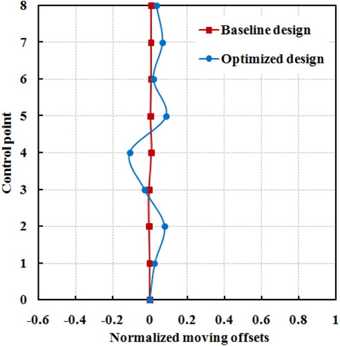
To give a quantitative comparison for the change of control points of the blade stacking line, the axial movement offset for control point of the Bezier curve is shown in Figure . After the sweep optimization design, it is found that the control points H1 and H2 at the hub region have moved backward. At mid-span region, the control points H3 and H4 have shown forward axial movements. From the mid-span to the tip, the control points H5 to H8 have all presented backward movements along the axial direction, but the specific values of the moving offsets are different. Since the Bezier curve is able to give quite good approximations to very complex curves, the movements of the control points of the Bezier curve could guarantee the stacking line smoothly and continuously changing.
Figure 7. Flowchart of the overall optimization design process.
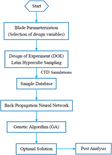
Figure 8. Schematic graph of blade sweep definition.
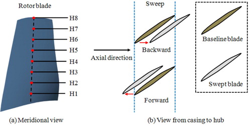
Figure 9. Comparison of the locations for control points of the stacking line.
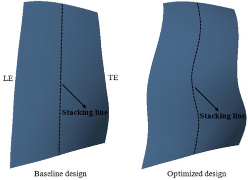
Furthermore, the blade geometries in the meridional view are compared between baseline rotor and optimized one as shown in Figure . It is noted that compared to baseline rotor, the optimized rotor presents a forward sweep near the mid span and a backward sweep near the hub and the tip ends. On the whole, the stacking line of optimized rotor blade has shown an S shape in the meridional view after the sweep optimization.
Figure 10. Comparison of blade shapes in the meridional view.
5.2. Performance comparison
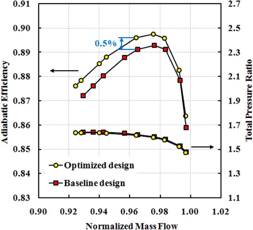
In the optimization design process, 3-D full-annulus steady CFD calculations have been utilized for providing the predictions of compressor aerodynamic performances under distorted inflow condition. Therefore, the performance maps between baseline rotor and optimized one are firstly compared and the comparison result is shown in Figure . It is found that the adiabatic efficiency of optimized rotor is higher than that of baseline one in the entire operating range, while the total pressure ratio is maintained. An approximately 0.5% improvement of adiabatic efficiency is obtained at near peak efficiency condition.
Figure 11. Comparisons of the compressor performance maps (steady results).
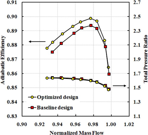
To further validate the optimization results, 3-D full-annulus unsteady CFD calculations have been implemented. Figure plots the comparison results for performance maps between the baseline and optimized designs. The unsteady simulation results have presented a similar trend as the steady simulation results in terms of the aerodynamic performance improvements achieved by the sweep design optimization. In the entire operating range, the optimized rotor performs better than the baseline rotor with respect to adiabatic efficiency. Moreover, the compressor total pressure ratio has been maintained. It can be also found that the aerodynamic performance benefit achievements will become more notable when the operating condition comes closer to the numerical stall point. The results validate the effectiveness of optimized rotor sweep design.
Figure 12. Comparisons of the compressor performance maps (unsteady results).
The above computational results suggest that rotor blade sweep design is beneficial for enhancing the overall aerodynamic performances of the transonic axial-flow compressor under total pressure distorted inflow condition. In the following sections, full-annulus unsteady CFD simulations will be used to make full analyses of variations of flow losses and explore the mechanisms for compressor aerodynamic performance improvements.
5.3. Effects on the leakage loss
For the transonic axial-flow compressors, the tip leakage loss, which often includes flow losses in the clearance and aerodynamic losses induced by the leakage and main flow interactions, is regarded as a major source of flow losses and can significantly affect the compressor overall performances. In this section, the attentions have been mainly focused on the influences of the optimized rotor sweep design on the overall tip leakage loss at the optimization point.
The rotor sweep design has large effects on the blade load distributions. The blade load, which is due to the pressure differences of the pressure side and suction side, has a very significant influence on the strength of leakage flows. To evaluate the blade load distributions near the tip when the rotor travels across the distorted and undistorted regions, the pressure coefficient is utilized and expressed as:
(5)
(5) where Pwall denotes the static pressure on blade surfaces.
and Pin are the total pressure and static pressure on the inlet plane of computational domain.
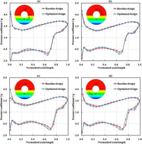
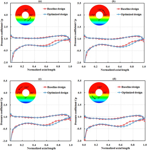
Figure compares pressure coefficient distributions along the chordwise direction for baseline and optimized rotor designs near the blade tip (at 98% blade span). As shown in Figure (a), as the rotor is leaving the distortion region, the sweep design has increased the pressure on the suction surface from 10% to 50% axial chord length, while the pressure on the pressure surface is nearly unchanged. Therefore, the local blade load from 10% to 50% axial chord length location is reduced. When the rotor blade moves out of the distorted region as depicted in Figure (b), a similar pressure coefficient variation trend as that in Figure (a) is also observed. In the meanwhile, as described in Figure (c), when the rotor blade moves towards the distorted region, the sweep design has decreased the pressure on the pressure surface but increased the pressure on the suction surface from about 10% to 50% axial chord length, leading to a reduction of the local blade load. As the rotor is entering distortion region as depicted in Figure (d), a similar pressure coefficient variation trend as that in Figure (c) is also found. The above results suggest that the blade sweep design has redistributed the blade loads in tip region and reduced the local blade load from about 10% to 50% axial chord length location, which can be beneficial for reducing the intensity of tip leakage flows.
Figure 13. Comparisons of the chordwise distributions of pressure coefficients on blade surfaces for baseline and optimized designs in the tip region ((a) 49° circumferential location; (b) 131° circumferential location; (c) 229° circumferential location; (d) 311° circumferential location).
Furthermore, to evaluate the intensity of tip leakage flow, the normal momentum of the local leakage flow, which is perpendicular to the chordwise direction, has been utilized and defined as:
(6)
(6)
(7)
(7)
(8)
(8) where ρ is the density of working fluid, WN is the relative velocity at the outlet of the tip clearance, h is the tip clearance size and also the height of a tip leakage flow element, dl is the width of the tip leakage flow element,
mainflow is the local mass flow of the mainstream in the tip region (from 75% to 100% span) for the local blade channel, WZ is the relative axial velocity of the main flow, and ξ is the local blade stagger angle. In this way, a lower normal momentum of the local leakage flow would mean a lower-momentum cross flow in the tip clearance and less aerodynamic losses.
Figure compares the normal momentum of the tip leakage flow at the outlet of the clearance for the chordwise locations between the baseline and optimized designs. A total number of four circumferential locations, which include the blades at 49°, 131°, 229° and 311° pitchwise positions, are given to present the normal momentum distributions of tip leakage flow. The 49°, 131°, 229° and 311° circumferential locations represent typical positions of the rotor blade leaving the distorted region, moving out of the distorted region, moving towards the distorted region and entering the distorted region. For the baseline rotor, comparing the momentum of the cross flow in tip clearance at different circumferential locations, it is observed that the rotor blade suffers from higher normal momentum of leakage flow when it is leaving and entering the distortion region in Figures (a) and (d) than when it is moving out of and moving towards the distortion region in Figures (b) and (c). Moreover, the highest normal momentum of leakage flow occurs in the process of the rotor blade leaving the distortion region.
Figure 14. Comparisons of normal momentum of tip leakage flows along the chordwise direction for baseline and optimized designs ((a) circumferential location 49°; (b) circumferential location 131°; (c) circumferential location 229°; (d) circumferential location 311°).
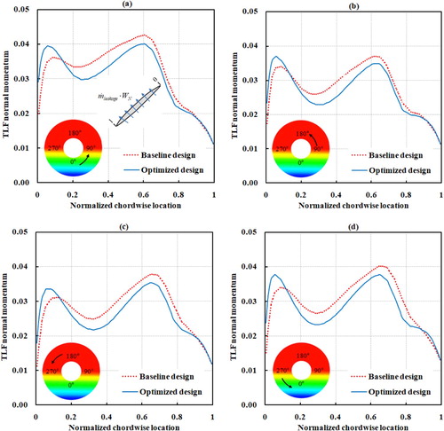
After the sweep optimization design, the results show that for different circumferential locations, the momentum of the cross flow in tip clearance is dereased from about 10% to 90% chordwise locations and notable reductions are mainly focused on 10% to 60% chordwise locations. In the meanwhile, it can be found that notable reductions for the normal momentum of leakage flow occur in the processes of the rotor blade leaving and entering the distortion region. The reductions of the normal momentum of leakage flow would eliminate the intensity of leakage flow, which is beneficial for suppressing the leakage loss in tip clearance.
To present the overall aerodynamic loss distributions for the flows in the tip clearance, the entropy creation is used because, unlike stagnation enthalpy, stagnation pressure and kinetic energy, its value will be independent of whether it’s obtained in the rotational frame or the stationary frame (Denton, Citation1993). The entropy distributions in the tip clearance at about 20% chordwise location are compared as described in Figure . For the baseline rotor, comparing the entropy distributions in the clearance at different circumferential locations, it can be found that more aerodynamic losses are suffered as the rotor blade is immersed in the distortion region (Figures (a) and (d)) than as the rotor blade is out of the distortion region (Figures (b) and (c)). Specifically, it is also noted that the most serious aerodynamic losses in clearance occur as the rotor is leaving the distortion region as shown in Figure (a). In the meanwhile, compared with the aerodynamic losses in clearance as the rotor is leaving the distortion region, less aerodynamic losses in clearance have been suffered as the rotor blade is entering the distortion region as shown in Figure (d). In the meanwhile, the rotor blade suffers from approximately the similar amount of aerodynamic losses in the clearance when it moves out of the distorted region as those when it moves towards the distorted region as depicted in Figures (b) and (c).
Figure 15. Comparisons of the entropy distributions in the rotor tip clearance of baseline and optimized designs.
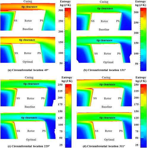
After the sweep optimization design, as the rotor is leaving and entering the distortion region as plotted in Figures (a) and (d), it can be observed that the high entropy regions in the clearance are suppressed and the local aerodynamic losses are significantly reduced. In the meanwhile, similar flow phenomena and loss variation trends have also been found in the clearance due to the optimized sweep design when the rotor is moving out of and moving towards the distorted region as shown in Figures (b) and (c). Moreover, the rotor sweep optimization design has achieved more aerodynamic performance improvements in the clearance when the rotor operates in the distortion region than those when the rotor operates out of the distortion region. The result suggests that the optimized rotor sweep design has successfully reduced the flow losses in the clearance, especially at the time when the rotor is working in the distortion region.
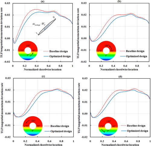
Then, the aerodynamic losses caused by the tip leakage and main flow interactions are discussed. In the rotor tip region, the flow runs across the clearance because of pressure differences of the pressure and suction surfaces. The leakage flows interact with the mainstreams and lead to the formation of leakage vortex in the tip regions, which will result in flow blockages and aerodynamic losses. In this situation, the intensity of the mixing process would largely depend on the difference of the momentum between the leakage and main flows. To evaluate the momentum deviation of these two flows, the tangential momentum deviation rate has been used and expressed as:
(9)
(9) where WP is the relative velocity along the chordwise direction in tip clearance. In this way, a larger tangential momentum deviation rate between the leakage flows and the mainstreams means a serious leakage and main flow interaction and therefore a high mixing loss in the blade passage.
Figure compares the tangential momentum deviation rate between the leakage flow and mainstream in the chordwise locations for baseline and optimized designs. For different circumferential locations on the whole annulus, it is observed that the optimized rotor sweep design has decreased the tangential momentum deviation rate between the leakage flow and mainstream. The reduced chordwise momentum difference between the leakage flow and the mainstream would be beneficial for suppressing the leakage and main flow interaction in the blade passage, indicating weakened leakage vortex and decreased mixing loss.
Figure 16. Comparisons of the tangential momentum deviation rate along the chordwise direction for baseline and optimized designs ((a) circumferential location 49°; (b) circumferential location 131°; (c) circumferential location 229°; (d) circumferential location 311°).
To describe the leakage flow trajectories and the leakage and main flow interactions, Figure makes a comparison of the entropy contours on blade-to-blade surfaces at different pitchwise locations between baseline and optimized rotor sweep designs in the tip region. Generally, the leakage vortex will travel across the blade passage to the adjacent blade pressure surface, which will result in a low-momentum fluid region. In this situation, the size and distribution of low-momentum fluid regions can be used to measure the intensity of tip leakage and main flow interactions.
Figure 17. Comparison of entropy contours on blade-to-blade surfaces between the baseline and optimized rotor designs near the tip (98% blade span). (a) Rotor blade leaving distortion region. (b) Rotor blade moving out of distortion region. (c) Rotor blade moving towards distortion region. (d) Rotor blade entering distortion region.

For the baseline rotor design, comparing the entropy distributions of the low-momentum fluid regions in the blade passage at different circumferential locations, it can be found that higher entropy values and more aerodynamic losses in the passage are suffered when the rotor is in the process of leaving the distorted region (Figure (a)) than when the rotor blade is entering and out of the distortion region (Figures (b–d)). It means that much higher flow blockages and more interaction loss have been generated when the rotor is in the process of leaving the distortion region. After the sweep optimization, as the rotor is leaving the distortion region as described in Figure (a), both the peak values and the size of high entropy regions are reduced and correspondingly the interaction loss is also decreased near the blade tip. As the rotor is moving out of the distortion region as shown in Figure (b), it is found that the optimized sweep design has also reduced the areas of high entropy regions and achieved lower leakage flow and mainstream interaction loss near the tip. As described in Figures (c) and (d), when the rotor blade is in the process of moving towards and entering the distortion region, the optimized sweep design has also decreased the size of high entropy regions and suppressed the local flow blockages, but the overall aerodynamic benefits achievements are lower than those when the rotor blade is in the process of leaving and moving out of the distortion region. On balance, the results indicate that the optimized sweep design successfully reduces the intensity of the tip leakage and main flow interactions near the tip and the associated flow losses, while more aerodynamic performance improvements are achieved in the process of the rotor blade leaving and moving out of distortion region.
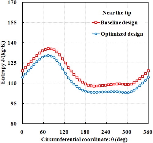
Furthermore, the comparisons of the circumferential distributions of the entropy at rotor outlet are made near the tip. The comparison results between baseline and optimized rotor designs are given in Figure . It is found the optimized sweep design shows lower entropy values at the rotor outlet than the baseline design in both the distorted and undistorted regions along the full circumferential locations. It means that lower aerodynamic loss has been achieved by the optimized sweep rotor due to eliminations of the tip leakage and main flow interactions. In the meanwhile, the results also indicate that the sweep optimization design is beneficial for suppressing the aerodynamic losses in the rotor tip region under the total pressure inflow distortion condition.
Figure 18. Comparison of the circumferential distributions of the entropy between baseline and optimized designs at 98% spanwise location.
5.4. Effects on the hub flow separations
For a transonic axial-flow compressor rotor, flow separations might occur in the blade hub region even for a well designed blade, especially under the inlet total pressure distortion condition. The separation loss is another major source of flow losses in the rotor blade passage and can significantly affect the compressor overall aerodynamic performances (Hu et al., Citation2019; Wang & Wu, Citation2019). In this section, the influences of the optimized rotor sweep design on the hub flow separations have been discussed.
The comparisons of pressure coefficients along the chordwise direction are made between baseline and optimized rotor designs for different circumferential locations near the hub. The results are described in Figure . From the pressure coefficient distributions for the baseline design, it can be found that serious flow separations occur from the location of approximately 80% chord length to the blade trailing edge. Moreover, flow separations are most seriously onset for the blades in the process of leaving the distortion region as depicted in Figure (a) compared with those for the blades in other processes as depicted in Figures (b–d). After the sweep optimization design, the results of the pressure coefficient distributions on blade suction surfaces near the trailing edge indicate that the local pressure rise ability for the blades at different pitchwise locations has been recovered at rear half of the airfoil sections, while the pressure coefficient distributions are nearly unchanged in the remaining chordwise locations.
Figure 19. Comparisons of the chordwise distributions of pressure coefficients near the hub between baseline and optimized rotor designs ((a) from 0° to 90° circumferential locations; (b) from 90° to 180° circumferential locations; (c) from 180° to 270° circumferential locations; (d) from 270° to 360° circumferential locations).
Furthermore, to give a quantitative evaluation of the variation of flow separation and separation loss, Figure compares the entropy contours on blade-to-blade surfaces between the baseline rotor design and the optimized one at different circumferential locations in the hub region. For the baseline rotor, comparing the entropy distributions on suction surfaces near the blade trailing edge, it is observed that the separations have presented a non-uniform distribution in the pitchwise direction. Moreover, the highest intensity of the flow separation and the most serious separation loss occur when the rotor is in the process of leaving distortion region, which corresponds to the result of the pressure coefficient distributions. After the rotor sweep optimization design, the hub flow separations on suction surfaces have been significantly suppressed near the blade trailing edge for all circumferential locations, including the blade leaving, moving out of, moving towards and entering distortion region. At the same time, the separation losses are also notably decreased and the rotor outflows have shown more uniform distributions. On the whole, compared with the aerodynamic benefits achievements in the process of the blade moving out of, moving towards and entering distortion region as depicted in Figures (b–d), more aerodynamic benefits have been achieved by the optimized rotor sweep design in the process of the blade leaving distortion region as described in Figure (a). The results also suggest that the optimized sweep design is effective on alleviating the hub flow separations and the associated separation losses under the inlet distortion condition.
Figure 20. Comparisons of entropy contours on blade-to-blade surfaces near the hub between baseline and optimized designs at different circumferential locations.
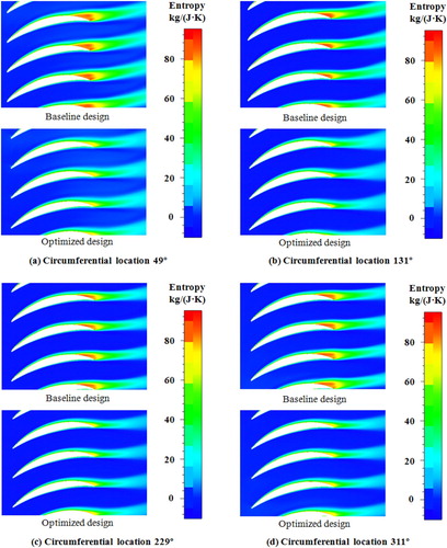
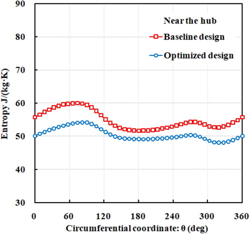
Figure gives a description of the entropy distributions of the baseline design and the optimized one in the pitchwise direction near the hub at the outlet of the rotor. Since the flow separations near the trailing edge have been successfully eliminated, the optimized sweep design has achieved lower entropy values at the rotor outlet than the baseline design in both the distorted and undistorted regions along full circumferential locations. It means that the optimized rotor has successfully decreased the hub flow separation loss under the total pressure inflow distortion condition.
Figure 21. Comparison of entropy distributions in the pitchwise direction between baseline and optimized designs at 5% spanwise location.
6. Conclusions and remarks
This paper conducts an investigation of the potential of sweep design for improving the aerodynamic performance of a transonic compressor rotor operating at total pressure distorted inflow condition. The major purpose is to offer some useful guidelines for compressor aerodynamic design to achieve high aerodynamic performances at distorted inflow condition. The 3-D full-annulus unsteady CFD calculations are used to analyze the flow fields in optimized rotor and further reveal the mechanisms for performance improvements. The main conclusions could be summarized as follows:
The inflow distortion has resulted in non-uniform distributions of the tip leakage loss in the clearance and the tip leakage and main flow interaction loss along the circumferential direction in the tip region. It is also found that the rotor blade suffers from the highest leakage loss in the process of the blade leaving distortion region. After the sweep optimization design, both the tip leakage loss in the clearance and the tip leakage and main flow interaction loss have been notably reduced due to the reduction of both the normal momentum of tip leakage flow and the tangential momentum deviation between the leakage and main flows. Specifically, for different circumferential locations, the optimized rotor sweep design has achieved more aerodynamic performance improvements in the process of the rotor blade leaving distortion region than those in the processes of the rotor blade moving out of, moving towards and entering distortion region.
In the hub region, serious flow separations are presented due to the inflow distortion. Similarly, the hub separations have shown a non-uniform distribution in the pitchwise direction and the rotor blade suffers from the highest separation loss in the process of the blade leaving distortion region. The optimized rotor successfully eliminates the hub flow separations in terms of the intensity and size along full circumferential locations. In the meanwhile, compared with the separation loss reduction in the process of the blade moving out of, moving towards and entering distortion region, more aerodynamic benefits achievement for the hub separation loss is in the process of the blade leaving distortion region. Moreover, the optimized sweep design has also achieved a more uniform rotor outflow distribution in the circumferential direction near the hub.
Due to the reductions of the leakage loss and hub separation loss, the sweep optimization design has improved the overall aerodynamic performances for the transonic axial-flow compressor. Specifically, for the compressor performance maps, the optimized rotor design has shown a higher adiabatic efficiency than the baseline design in the entire operating range, while maintaining the total pressure ratio. An approximately 0.5% efficiency improvement has been achieved by the optimized design at the optimization point. In the meanwhile, more notable performance enhancements are observed when the rotor operates closer to the low mass flow operating condition. The computational results suggest that the sweep optimization design considering inflow non-uniformity has presented a significant potential for improving the overall aerodynamic performance of a transonic axial-flow compressor rotor at the distorted inflow condition and will be a probable effective way for a transonic compressor rotor to resist non-uniform inflows.
Nomenclature
| Cp | = | pressure coefficient |
| h | = | tip clearance size |
| = | mass flow rate | |
| = | total pressure | |
| p | = | static pressure |
| = | total temperature | |
| = | non-dimensional wall distance | |
| W | = | relative velocity |
Greek Symbols
| η | = | adiabatic efficiency = [ |
| = | specific heat ratio | |
| = | total pressure ratio = | |
| ρ | = | working fluid density |
| ξ | = | stagger angle |
Subscripts
| base | = | baseline |
| in | = | inlet |
| max | = | maximum |
| min | = | minimum |
| out | = | outlet |
| opt | = | optimized |
| ref | = | reference value |
Abbreviations
| BLI | = | boundary layer ingestion |
| CFD | = | computational fluid dynamics |
| deg | = | degree |
| DOE | = | design of experiment |
| GA | = | genetic algorithm |
| LE | = | leading edge |
| TE | = | trailing edge |
| TFL | = | tip leakage flow |
| VIGV | = | variable inlet guide vane |
Acknowledgment
The authors would like to gratefully acknowledge the support by the National Natural Science Foundation of China (Nos. 51906005, 51706008, 51976005 and 51636001), China Postdoctoral Science Foundation (No. 2018M641150), Aeronautics Power Foundation (No. 6141B09050375), the open fund from Xihua University (No. ZNKD2020-002), the open fund from National Key Laboratory of Sciencer and Technology on Aero-Engine Aero-Thermodynamics (No. 6142702180101) and National Science and Technology Major Project (2017-II-0005-0018).
Disclosure statement
No potential conflict of interest was reported by the author(s).
Additional information
Funding
References
- Ardabili, S. F., Najafi, B., Shamshirband, S., Bidgoli, B. M., Deo, R. C., & Chau, K. W. (2018). Computational intelligence approach for modeling hydrogen production: A review. Engineering Applications of Computational Fluid Mechanics, 12(1), 438–458. https://doi.org/10.1080/19942060.2018.1452296
- Benini, E., & Biollo, R. (2007). Aerodynamics of swept and leaned transonic compressor rotors. Applied Energy, 84(10), 1012–1027. https://doi.org/10.1016/j.apenergy.2007.03.003
- Biollo, R., & Benini, E. (2009). Shock/boundary-layer/tip-clearance interaction in a transonic rotor blade. Journal of Propulsion and Power, 25(3), 668–677. https://doi.org/10.2514/1.39541
- Chen, X., & Agarwal, R. K. (2013). Optimization of wind turbine blade airfoils using a multi-objective genetic algorithm. Journal of Aircraft, 50(2), 519–527. https://doi.org/10.2514/1.C031910
- Chen, X., & Agarwal, R. K. (2014). Shape optimization of airfoils in transonic flow using a multi-objective genetic algorithm. Proceedings of the Institution of Mechanical Engineers, Part G: Journal of Aerospace Engineering, 228(9), 1654–1667. https://doi.org/10.1177/0954410013500613
- Cousins, W. T., Georges, M. J., & Rezaei, H. (2003). Inlet distortion testing and analysis of a high-bypass ratio turbofan engine (ISABE-2003-1110).
- Cui, W., Xiang, X., Zhao, Q., & Xu, J. (2016). The effect of sweep on flow fields of a highly loaded transonic rotor. Aerospace Science and Technology, 28(2016), 71–81. https://doi.org/10.1016/j.ast.2016.08.002
- Denton, J. D. (1993). Loss mechanisms in turbomachines. Journal of Turbomachinery, 115(4), 621–654. https://doi.org/10.1115/1.2929299
- Elfarra, L. A. (2019). Optimization of helicopter rotor blade performance by spline-based taper distribution using neural networks based on CFD solutions. Engineering Applications of Computational Fluid Mechanics, 13(1), 833–848. https://doi.org/10.1080/19942060.2019.1648322
- Fidalgo, V. J., Hall, C. A., & Colin, Y. (2012). A study of fan-distortion interaction within the NASA Rotor 67 transonic stage. Journal of Turbomachinery, 134(5), 051011. https://doi.org/10.1115/1.4003850
- Florea, R. V., Voytovych, D., Tillman, G., Stucky, M., Shabbir, A., Sharma, O., & Arend, D. J. (2013). Aerodynamic analysis of a boundary-layer-ingesting distortion-tolerant fan (ASME Paper No. GT2013-94656).
- Gunn, E. J., & Hall, C. A. (2014). Aerodynamics of boundary layer ingesting fans (ASME Paper No. GT2014-26142).
- Guo, J., & Hu, J. (2018). A three-dimensional computational model for inlet distortion in fan and compressor. Proceedings of the Institution of Mechanical Engineers, Part G: Journal of Aerospace Engineering, 232(2), 144–156. https://doi.org/10.1177/0957650917719811
- Hah, C., Puterbaugh, S. L., & Wadia, A. R. (1998). Control of shock structure and secondary flow field inside transonic compressor rotors through aerodynamic sweep (ASME Paper No. 98-GT-561).
- Hah, C., Rabe, D. C., Sullivan, T. J., & Wadia, A. R. (1996). Effects of inlet distortion on the flow field in a transonic compressor rotor (ASME Paper No. 96-GT-547).
- Hall, D. K., Greitzer, E. M., & Tan, C. S. (2017). Analysis of fan stage conceptual design attributes for boundary layer ingestion. Journal of Turbomachinery, 139(7), 071012. https://doi.org/10.1115/1.4035631
- Hawthorne, W. R., Mitchell, N. A., McCune, J. E., & Tan, C. S. (1978). Nonaxisymmetric flow through annular actuator disks: Inlet distortion problem. Journal of Engineering for Power, 100(4), 604–617. https://doi.org/10.1115/1.3446409
- Horlock, J. H. (1979). Actuator disk theory: Discontinuities in thermo-fluid dynamics. McGraw-Hill Companies.
- Hu, J., Wang, R., & Huang, D. (2019). Improvements of performance and stability of a single-stage transonic axial compressor using a combined flow control approach. Aerospace Science and Technology, 86(2019), 283–295. https://doi.org/10.1016/j.ast.2018.12.033
- Kennedy, S., Robinson, T., & Spence, S. (2014). Computational investigation of inlet distortion at high angles of attack. Journal of Aircraft, 51(2), 361–376. https://doi.org/10.2514/1.C031789
- Liu, H., Wang, Y., Xian, S., & Hu, W. (2018). Effect of inlet distortion on the performance of axial transonic contra-rotating compressor. Proceedings of the Institution of Mechanical Engineers, Part G: Journal of Aerospace Engineering, 232(1), 42–54. https://doi.org/10.1177/0954410016670421
- Longley, J. P., & Greitzer, E. M. (1992). Inlet distortion effects in aircraft propulsion system integration (NASA Technical Report No. AGARD-LS-1832).
- Lu, H., Yang, Z., Pan, T., & Li, Q. (2019). Non-uniform stator loss reduction design strategy in a transonic axial-flow compressor stage under inflow distortion. Aerospace Science and Technology, 92(2019), 347–362. https://doi.org/10.1016/j.ast.2019.06.015
- Mazzawy, R. S. (1977). Multiple segment parallel compressor model for circumferential flow distortion. Journal of Engineering for Power, 99(2), 288–296.
- Mohsen, M., Owis, F. M., & Hashim, A. A. (2017). The impact of tandem rotor blades on the performance of transonic axial compressors. Aerospace Science and Technology, 67(2017), 237–248. https://doi.org/10.1016/j.ast.2017.04.019
- Pearson, H., & McKenzie, A. B. (1959). Wakes in axial compressors. The Aeronautical Journal, 63(583), 415–416. https://doi.org/10.1017/S0368393100071273
- Scott McNulty, G., Decker, J. J., Beacher, B. F., & Khalid, S. A. (2004). The impact of forward swept rotors on tip clearance flows in subsonic axial compressors. Journal of Turbomachinery, 126(4), 445–454. https://doi.org/10.1115/1.1773852
- Shaw, M. J., Hield, P., & Tucker, P. G. (2014). The effect of inlet guide vanes on inlet flow distortion transfer and transonic fan stability. Journal of Turbomachinery, 136(2), 021015. https://doi.org/10.1115/1.4024906
- Strazisar, A. J., Wood, J. R., Hathaway, M. D., & Suder, K. L. (1989). Laser anemometer measurements in a transonic axial-flow fan rotor (NASA Technical Paper 2879).
- Suarez, J. M., Flaszynski, P., & Doerffer, P. (2018). Streamwise vortex generator for separation reduction on wind turbine rotors. International Journal of Numerical Methods for Heat & Fluid Flow, 28(5), 1047–1060. https://doi.org/10.1108/HFF-05-2017-0203
- Sun, P., Fu, W., Wang, H., & Zhong, J. (2019). Numerical research on inlet total pressure distortion in a transonic compressor with non-axisymmetric stator. Proceedings of the Institution of Mechanical Engineers, Part G: Journal of Aerospace Engineering, 233(2), 667–678. https://doi.org/10.1177/0954410017740385
- Sun, P., Gao, H., Zhong, J., & Yang, M. (2013). Study on the influence of total pressure distortion on the end wall flow field in a supersonic compressor (ASME Paper No. GT2013-94729).
- Thollet, W., Dufour, G., Carbonneau, X., & Blanc, F. (2016). Body-force modeling for aerodynamic analysis of air intake-fan interactions. International Journal of Numerical Methods for Heat & Fluid Flow, 26(7), 2048–2065. https://doi.org/10.1108/HFF-07-2015-0274
- Triantafyllou, T., Nikolaidis, T., Diakostefanis, M., & Pilidis, P. (2018). Stability assessment of an airflow distorted military engine's fan. Proceedings of the Institution of Mechanical Engineers, Part G: Journal of Aerospace Engineering, 232(13), 2584–2592. https://doi.org/10.1177/0954410017716478
- Valencia, E., Hidalgo, V., Nalianda, D., Panagiotis, L., & Singh, R. (2017). Discretized miller approach to assess effects on boundary layer ingestion induced distortion. Chinese Journal of Aeronautics, 30(1), 235–248. https://doi.org/10.1016/j.cja.2016.12.005
- Venturelli, G., & Benini, E. (2016). Kriging-assisted design optimization of S-shape supersonic compressor cascades. Aerospace Science and Technology, 58(2016), 275–297. https://doi.org/10.1016/j.ast.2016.08.021
- Wang, B., & Wu, Y. (2019). Passive flow control of the corner separation in an annular compressor cascade with a micro-blade. Proceedings of the Institution of Mechanical Engineers, Part A: Journal of Power and Energy, 233(3), 293–308. https://doi.org/10.1177/0957650918787882
- Williams, D. D. (1987). Review of current knowledge on engine response to distorted inflow conditions (AGARD conference proceedings).
- Zhao, J., Wang, Z., Zhao, Y., & Xi, G. (2018). Investigation of transient flow characteristics inside a centrifugal compressor for design and off-design conditions. Proceedings of the Institution of Mechanical Engineers, Part A: Journal of Power and Energy, 232(4), 364–385. doi: 10.1177/0957650917738848