
 ?Mathematical formulae have been encoded as MathML and are displayed in this HTML version using MathJax in order to improve their display. Uncheck the box to turn MathJax off. This feature requires Javascript. Click on a formula to zoom.
Abstract
This paper mainly proposed a dynamic control method of particle distribution uniformity in a rolling circulating fluidized bed (RCFB) by using an air distribution plate. An Euler–Euler numerical simulation approach which is called two-fluid flow model is used to simulate the behaviors multiphase flow within the RCFB. Six different tilt angles θ which are θ = 2°, 5°, 8°, 10°, 12° and 15° are used for the fixed inclination state of the RCFB, meanwhile, eight different inclined angles φ which are φ = −2°, −5°, 0°, 2°, 5°,8°, 10° and 12° are used for the location of the air distribution plate. After performing the simulation, the following three different conclusions are obtained. Firstly, with the increase of θ, serious uneven distribution behaviors for particles are founded at the lower position of the riser which is a part of the RCFB. Secondly, by adjusting φ, the uneven phenomenon of particles distribution behaviors is able to be alleviated no matter how θ changes for the RCFB. Thirdly, a function relation between θ and φ is obtained, which is verified by using the dynamic control method based on the dynamic mesh model in the RCFB.
1. Introduction
With the development of the society, ships have become one of the main means of transportation, especially, on the sea. According to the relevant data, 90% of China’s trade transportation is completed by marine transportation (Ma, Citation2017). As the rapid development of the shipping industry, a lot of exhaust gas produced in the transportation process has caused serious pollution to our environment (Jenaru & Acomi, Citation2016; Park et al., Citation2017). Therefore, how to reduce the emission of harmful substances in ship exhaust gas has become a research hotspot. At present, photo catalysis and low temperature plasma are used in the treatment of ship tail gas (Zhang et al., Citation2016). However, due to high cost and safety problems, they do not use in real ships. As a rolling circulating fluidized bed (RCFB) has many advantages such as high exhaust gas treatment capacity, high heat transfer efficiency and low manufacturing cost (Wahyudi et al., Citation2016), thus, the RCFB is usually used as a new treatment device for the ship exhaust gas, There are many calcium carbonate (CaCO3) particles in the RCFB which can effectively remove the harmful substances from the exhaust gas and achieve desulfurization (Cai et al., Citation2019; Xia & Peng, Citation2007). Due to the influence of wind and waves on the ship, the RCFB encountered with different amplitude and period. The rolling of the RCFB results in the massive accumulation of calcium carbonate particles on the wall of the riser, and the uneven distribution of particles seriously affect the desulfurization efficiency of the RCFB. After reading the previously published papers, it is found that there are only several papers focused on the RCFB. Hiroyuki Murata et al. (Murata et al., Citation2012) measured the heat transfer coefficient between the wall and the multiphase flow within the RCFB by experimental method, and analyzed the influence of such parameters as rolling frequency, rolling period, rolling amplitude and other parameters of the circulating fluidized bed (CFB) on the heat transfer coefficient. Tong Zhao et al. (Citation2014) studied the effect of rolling motion on particle distribution in the RCFB, and found that rolling motion mainly affects the radial distribution of particles in the radial direction in the riser, and the particle volume fraction showed a periodic change. At the same time, Tong Zhao et al. (Citation2016) studied the influence of the rolling parameters which include amplitude and period on the multiphase flow status within the RCFB, they illustrated that rolling amplitude has much effect on particle distribution behaviors than rolling period. However, the evenly distributed particles in the RCFB have a great influence on the efficiency of the RCFB (Anantharaman et al., Citation2017; Song et al., Citation2020; Zhang, Citation2020), thus, it is very necessary to guarantee the uniformly distributed particles within the RCFB.
Based on particle distribution behaviors in the RCFB, a dynamic control method is proposed to solve the problem of the reduction the harmful substances of exhaust gas for the RCFB. In the dynamic control method, an air distribution plate installed at the lower position of the RCFB’s riser is able to change its swing angle and the direction of gas imports.
In this paper, the rolling motion of the RCFB is discretized into fixed inclined states with different angles θ, meanwhile, the inclined angle of the air distribution plate φ is also changed. Through the simulation performed at the present work, the optimal φ corresponding to different θ is discovered, and the functional relationship between those two angles is analyzed, which is able to be regarded as the basis for dynamic regulation. Then the dynamic mesh model (He et al., Citation2018; He et al., Citation2020; Mnasri et al., Citation2010) is used to compare and analyze the dynamic control of air distribution plate with that of no control. The purpose of this manuscript is to reduce the exhaust gas for the RCFB by using the proposed the dynamic control method of the air distribution plate.
2. Mechanism and solution of particle accumulation in the RCFB
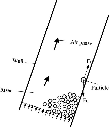
The RCFB swings to the left and right under the influence of wind and waves in actual work, so that the riser also tilt at different angles. There are many calcium carbonate (CaCO3) particles used to absorb sulfur dioxide (SO2) in the riser. Due to different degrees of inclination of the riser, the particles will accumulate on one side of the bottom of the riser, as shown in Figure . Particles in the riser are mainly affected by their gravity FG and the drag force of air relative to the particles FD (Tian & Peng, Citation2004). FD makes particles move upward, and particles also move downward under the influence of their own gravity. In the case that FD is less than the axial component of its own gravity, particles will move downward and pile up at the bottom of the riser, which is able to affect the working efficiency of the RCFB.
Figure 1. Accumulation of particles in the riser.
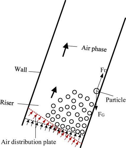
In the case that FD is increased, the accumulation of particles in the riser can be effectively solved. In the case that the air inlet direction is properly changed so as to the accumulated particles is able to well contact with the air, FD is then increased. As the RCFB is in a state of continuous rolling, its tilt angle is also changing continuously, so the air inlet direction is also changed. In this study, an air distribution plate is installed at the lower position of the riser, the air inlet direction is changed by adjusting the angle of the air distribution plate, which results in the increased FD, meanwhile, the uniform distribution of particles in the riser is ensured. Figure shows the dynamic control method of the air distribution plate, in order to realize this method, numerical simulation approach is used to simulate multiphase flow behaviors within the RCFB.
Figure 2. The dynamic control method of the air distribution plate.
3. The geometry model, simulation method & simulation conditions for the RCFB
In order to realize the dynamic control of the air distribution plate within the RCFB, it is necessary to calculate the functional relationship between the two tilting angles. In order to accurately find the functional relationship between the two tilting angles, this section firstly established the geometry model of the RCFB, and then used a pre-processing software to divide the mesh, finally the mesh is used to perform the simulation within FLUENT 16.2 software (Almuttahar & Taghipour, Citation2008). The periodic rolling of the RCFB is discretized into inclined states with different angles θ. The inclined angle of the air distribution plate φ is also changed. The particle distribution in the riser is analyzed, meanwhile, the corresponding angles between θ and φ with the most uniform particle distribution are found out by comparison.
3.1. The Geometry model of the simulation
The geometric model of the RCFB used for numerical simulation is shown in Figure (a), which is mainly composed of air distribution plate, riser, cyclone separator, downcomer and J-Valve. The exhaust gas of the engine enters the riser from the inlet, and the particles accumulated at the lower position of the riser move upward under the action of drag force FD. When passing through the cyclone separator, part of the air phase is output from the outlet, and the remaining air phase precipitates with the particles downward through the downcomer and J-Valve, and then returns to the riser under the action of the secondary inlet FD. The width, height and length of the riser are 288 mm, 2408 mm and 288 mm, respectively. Moreover, e = 650 mm is regarded as the distance between the midplane of the riser and the cyclone.
Figure 3. (a) Geometry model of the RCFB. (b) Rolling process of the RCFB.
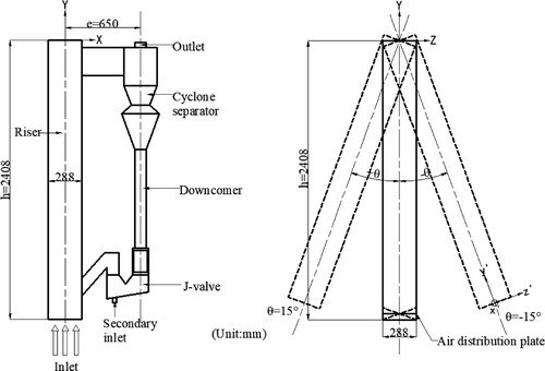
It is assumed that the X-axis is the longitudinal axis of the ship, and the Y-axis is the vertical axis of the ship. During the working process of the RCFB, the RCFB swings around X-axis, namely, from –z’ to +z’ or from +z’ to –z’. Herein, O-XYZ is the absolute coordinate system, and o’-x’y’z’ is the absolute coordinate system. This leads to the accumulation of calcium carbonate particles in the RCFB and affects the desulfurization effect. According to the swing law of the ship, the relationship between the continuous rolling of the circulating fluidized bed and the time becomes the sine function, that is, the reciprocating motion around the fixed axis X. The rolling process is shown in Figure (b), and the rolling function is shown in Equation (1).
(1)
(1) where θ is angular displacement of the RCFB, A is amplitude of the RCFB, ω is angular frequency of the RCFB, and t is time. In this paper, the maximum angular displacement of the RCFB is
= ± 15° (counter clockwise is positive). Because the motion of the RCFB is a symmetrical rolling around the origin O, only the rolling process with the inclination of 0–15° is considered in the simulation.
3.2. The applied method for the simulation
Based on the Euler–Euler two-fluid flow model, a numerical model of gas-solid two-phase flow in the RCFB is established (Ghalandari et al., Citation2019; Huai et al., Citation2012; Mosavi et al., Citation2019; Wu et al., Citation2017). After considering the continuity in terms of particle volume fraction and speed within a unit of the meh, the conservation of mass and momentum conservation equations are satisfied. In order to facilitate the calculation, the virtual mass force, the collision of particle itself, and the lifting force generated by movement are ignored, and the mass exchange between air and solid phases is not considered. In this study, only the hydrodynamic model consisting of the gravity of the particle and the drag force of the air phase is considered (Yan et al., Citation2020).
Generally speaking, as for flow problems, the mass conservation equation is able to be satisfied, which is shown in Equation (2) for air phase and Equation (3) for solid phase.
(2)
(2)
(3)
(3) Where
is volume fraction of air phase,
is volume fraction of particle,
is average density of air phase,
is average density of particle. Besides,
is velocity of air phase,
is velocity of particle.
The essence of momentum equation is to satisfy Newton's second law. The momentum conservation equation of gas-solid two-phase flow is shown in Equations (4) and (5).
(4)
(4)
(5)
(5) Where P is pressure,
is the particle pressure,
is drag force between gas-solid phases,
is gravitational acceleration.
At the same time, the standard k-ε turbulence model has been utilized to simulate the fixed RCFB with several tilt angles θ. The equations for the standard κ-ε turbulence model are shown as Equation (6), Equation (7), Equation (8) and Equation (9).
(6)
(6)
(7)
(7)
(8)
(8)
(9)
(9)
Where is the turbulent viscosity,
represents the generation of turbulence kinetic energy due to the mean velocity gradients, Cε1, Cε2, σε and σk are constants. Specifically, Cε1 equals to 1.44, Cε2 equals to 1.92, σε equals to 1.3 and σk equals to 1.0.
Moreover, the turbulent model for the RCFB which experienced the rolling motion is called RNG k-ε turbulence model. The equations for RNG k-ε turbulence model are shown as followings:
(10)
(10)
(11)
(11)
(12)
(12)
(13)
(13) wherein,
is the effective turbulent viscosity,
and
are constants. Specially,
and
.
and
are the inverse effective Prandtl numbers for k and ε, respectively.
3. Numerical simulation conditions
In this paper, Euler–Euler two-fluid flow model deals gas-solid two-phase flow (Hou et al., Citation2017) with turbulence model and Gidaspow drag model. The standard to evaluate the iteration stability of the simulation is that the momentum and mass residuals are less than 1.0 × 10⁻³. Moreover, the boundary conditions include velocity inlet and pressure outlet. The tail gas of the engine is simulated with air. Calcium carbonate (CaCO3) particles are used as desulfurizer in the RCFB. In the case that the RCFB is in a fixed tilt state of 2°, 5°, 8°, 10°, 12°, and 15°, the tilt angles of the air distribution plates are adjusted to -2°, -5°, 0°, 2°, 5°, 8°, 10°, and 12° (counter clockwise is positive), thus, it is clear that 6 × 8 = 48 different cases are numerically simulated. The simulation calculation cases are shown in Table , and the simulation parameter setting is shown in Table .
Table 1. Different Simulation calculation cases.
Table 2. Setting of simulation parameters.
4. The results of the simulation
4.1. Verification of the simulated results
Before analyzing the results of particle distribution in the RCFB, there is a need to perform the verification process of the current simulation. In this paper, the pressure gradient –ΔP/Δy′ (pressure change per unit distance) is the most important verification condition, namely, the different pressure gradient changes corresponding to different heights of the riser.
In this study, ANSYS MESH is used to divide the calculation model into a tetrahedral unstructured mesh, and the mesh quality is above 0.8. In order to ensure the accuracy of the calculation results, we verified the mesh independence of the calculation model in our previous paper (Wang et al., Citation2020), and finally selected 338249 mesh for later calculations.
Figure (a) shows the change value of pressure gradient and riser height when rolling amplitude is 0°. It shows that experiment and numerical simulation results are highly consistent. In Figure (b), the rolling amplitude A equals to 15°, the pressure gradient –ΔP/Δy′ decreases with the increase of riser height y′. It is clear that the results of numerical simulation are almost the same with those of the experiment. After combing Figure (a,b), the correctness of the simulation performed at the present work is initially verified.
Figure 4. The compared pressure gradient along with the riser height y′ in the RCFB between the simulation performed by Wang et al., Citation2020 and the experiment conducted by Zhao et al., Citation2016 (a) upright (θ = 0°), (b) θ = 15°
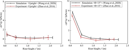
Moreover, Wang et al. (Citation2020) firstly compared the pressure gradient along the RCFB’s riser under various rolling amplitudes (5°, 10°, 15°) between the simulation and the experiment, and then verified the correctness of their numerical simulation methods. Specifically, the physical model and calculation method used at the present work are almost the same as those used in the work of Wang et al. (Citation2020). In this regard, as the rolling amplitudes of the present paper are 2° 5° 8° 10° 12° and 15°, which have been covered by ±15°, so the numerical simulation method in this paper is correct and reliable.
4.2. Particle distribution in the RCFB with different fixed inclinations
According to the current experimental data, it is known that the particles in the RCFB reach a stable state after 10 s of operation. In order to get more stable and accurate simulation results, the particle distribution in the riser is analyzed when the rolling time for the RCFB is 20 s. In the case that the RCFB is inclined at different angles 2°, 5°, 8°, 10°, 12° and 15°, meanwhile, the inclined angle of the air distribution plate φ is set to −2°, −5°, 0°, 2°, 5°, 8°, 10° and 12°, the particle distribution cloud diagrams in the riser are shown in Figure when the rolling time of the RCFB is 20 s.
Figure 5. Particle distribution in the riser with different inclined angles of air distribution plate.
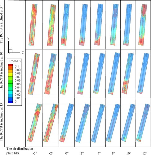
In Figure , red color indicates high particle volume fraction, blue color indicates low particle volume fraction, it is clear that in the case that the RCFB tilts to 2° and the air distribution plate tilts to 2°, 5° and 8°, the particle accumulation in the riser is alleviated. In the case that the CFB is inclined at 5° and the air distribution plate is inclined at 8° and 10°, the particles in the riser are less. In the case that the CFB is inclined at 8° and the air distribution plate is inclined at 10°, small particle volume fraction is founded within the riser, which results in the uniform particle distribution phenomena. In the case that the CFB is inclined at 10° and the air distribution plate tilts 5°, 8° and 12°, the particles at the bottom of the riser are not too much and the particle distribution is relatively uniform. In the case that the CFB is inclined at 12° and the air distribution plate is inclined at 8° and 12°, the particles accumulate less in the riser, and the distribution uniformity is good. In the case that the CFB is inclined at 15°, there is almost no accumulation of particles in the riser when the air distribution plate is inclined at 2° and 5°, and the particle distribution is very uniform.
4.3. Effects of inclined angles on particle volume fraction distribution within the RCFB
In order to more accurately analyze the influence of different air distribution plate tilt angle φ on the particle distribution in the riser, the Standard deviation with its average value are used in this study. Firstly, in the 16th, 18th and 20th seconds of the RCFB operation, five different cross-sections are selected with the same interval length along the RCFB’s riser. Meanwhile, n points are selected in each cross-section, and the Standard deviation difference of particle volume fraction on each cross-section is calculated respectively. Then the Standard deviation difference of each section in the 16th, 18th and 20th seconds is obtained, meanwhile, the average of those three standard deviation differences is also calculated. The larger of this average, the more obvious the particle packing phenomenon is. Meanwhile, the smaller of this average, the better the uniformity of particle distribution is. In terms of the above-mentioned analysis results, the final average of the standard deviation difference is able to be obtained by Equation (14).
(14)
(14) wherein, S represents the average of the standard deviation difference, n is the number of points taken on each section (
),
is the volume fraction of each point,
is the average volume fraction of each section.
Figure shows the variation of the Standard deviation changed with different inclined angles of air distribution plate φ. Herein, the RCFB is fixedly inclined at 2°, 5°, 8°, 10°, 12°, and 15°, the inclination angles of the air distribution plates are set to 0°, 2°, 5°, 8°, 10°, and 12°.
Figure 6. Standard deviation in the riser changed with different inclined angles of air distribution plate.
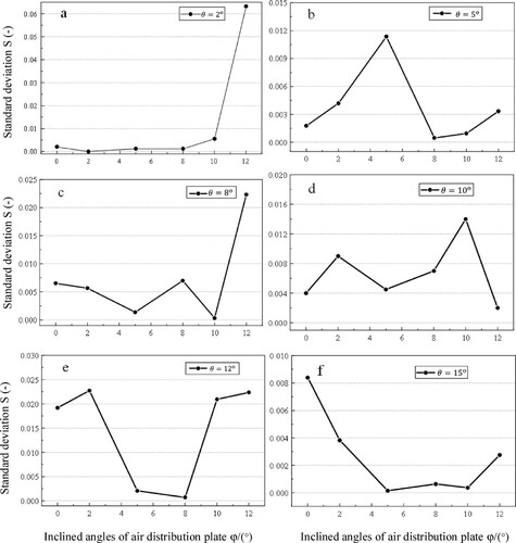
As shown in Figure (a), when the riser is tilted by 2° and the air distribution plate is tilted by 2°, the corresponding Standard deviation is the smallest. It can be seen from Figure (b–f) that when the riser is tilted by 5°, 8°, 10°, 12°, 15° and the air distribution plate is tilted by 8°, 10°, 12°, 8°, 5° respectively, the corresponding Standard deviation are the smallest.
5. Optimization and verification of dynamic control method
Through the analysis of the simulation results in section 4, it is found that the RCFB corresponds to an optimal air distribution plate dip angle under each fixed tilting state, which has the capability of dispersing particles to uniformly distribute within the RCFB. There is an assumption that in the case of finding the functional relationship between of the angle of the air distribution plate φ and the inclined angle of the RCFB θ, the local accumulation and uneven distribution of particles in the riser can be solved during the rolling behaviors of the RCFB. Because the dynamic control method is obtained in the case of static situation, thus, further verification is needed for dynamic continuous variation process. In this regard, the dynamic mesh model is used to realize the continuous rolling of the RCFB with the dynamic regulation of air distribution plate. The particle distribution in the whole cycle riser is analyzed and the feasibility of the scheme is verified.
5.1. Optimization of dynamic control function method
In this paper, data fitting of the dip angle relation between the air distribution plate and the RCFB is carried out in MATLAB. This is to realize the dynamic regulation of the air distribution plate to the particle distribution in the riser. During the curve fitting process, the goodness of fit is usually used to test the fitting accuracy, and the correlation index R2 is used to test the goodness of curve fitting.
(15)
(15) Where y is the actual value,
is the estimated value of y obtained by the curvilinear equation, and
is the average value of the actual value y.
After using the method of function fitting, the functional relationship between φ and θ is able to be expressed as:
(16)
(16)
The fitting effect is shown in Figure , the determination coefficient R2 = 0.96, and the precision is high.
Figure 7. Function fitting diagram of air distribution plate inclination angle and riser inclination angle.
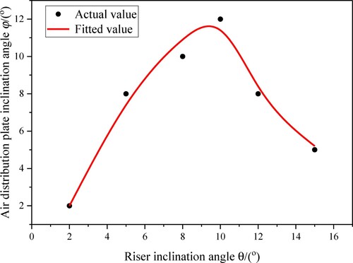
When the rolling angle of the RCFB θ changes continuously with time, the tilt angle of air distribution plate will change accordingly, as to realize the dynamic regulation of air distribution plate, so that particles in the riser can be evenly distributed. However, it can be seen from Figure that the curve obtained by fitting has a large range of change. If the total slope of the curve is used to represent it, that is, the sum of the absolute values of the slopes between adjacent points of the six points selected by simulation calculation, the total slope of the curve FM equals to 4.67. If the total slope of the function curve is large, φ is too large and the corresponding speed is too fast in the dynamic control, which is difficult to achieve under the actual conditions, and the operation stability of the RCFB is greatly affected. With the aim of controlling φ within a small range, MATLAB is used to fit the curve between the inclination angle of different air distribution plates and the particle distribution figure in the riser in the previous section.
Figure 8. Function diagram of riser inclination angle and air distribution plate inclination angle.
Then, the value range of the tilted angle of the air distribution plateis minimized by allowing the Standard deviation of the fitting curve not to be exactly the minimum but with a 10% possible change. By increasing the value range of φ, it is clear that uneven particles firstly tend to be more seriously distributed within the RCFB, then, the total slope of the change of the inclined angle of the air distribution plate can be reduced and a more reasonable fitting function can be obtained. In order to obtain the optimal solution within the range of the desirable inclination angle of the air distribution plate, the genetic algorithm in MATLAB is applied to find the optimal inclination angle of the air distribution plate (Razvan et al., Citation2015a, Citation2015b). The optimization steps are as follows:
Determine the optimization objective function. If the RCFB is tilted at 2°, the optimal solution in the range of the corresponding distribution plate inclination angle is
, and so on, the optimal solutions corresponding to the RCFB tilting at 5°, 8°, 10°, 12° and 15° are respectively
Determine the feasible region of the objective function. The two ranges of the inclination angle of the air distribution plate are taken as the feasible regions of the optimization objective function, Feasible region 1: [1.99,4.22], [8.01,9.72], [3.30,4.58], [4.81,5.99], [5.20,8.01], [4.88,5.72], Feasible region 2: [1.99,4.22], [0.18,1.27], [3.30,4.58], [4.81,5.99], [5.20,8.01], [4.88,5.72].
Find the best solution in the feasible region. In feasible region 1, the corresponding optimal solutions are:
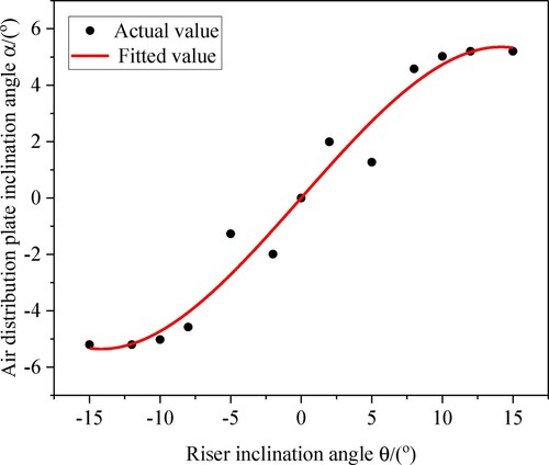
In the actual working condition, the ship is affected by the change of wind and waves, which causes the RCFB to swing together with the ship. In this case, the angle of the air distribution plate changes correspondingly with the rolling of the RCFB. In order to ensure more stable operation, it is essential to guarantee the smooth variation of φ. Therefore, when the RCFB experienced continuously the rolling behaviors, the functional relationship between φ and θ is able to be shown in Equation (18) and Figure . The goodness of fit R2 equals to 0.97, which is able to be regarded as high precision.
(18)
(18)
5.2. The verification of dynamic control method
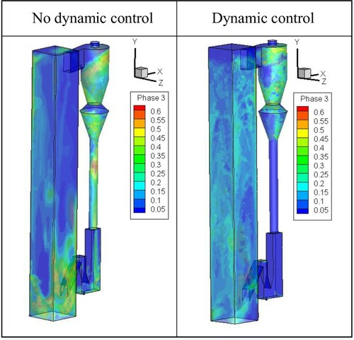
When the rolling behaviors are considered for the RCFB, a dynamic mesh model is able to be utilized to simulate this process. Specifically, the dynamic mesh model can automatically adjust the distribution of mesh nodes and reconstruct the mesh with the movement of boundary. In this paper, PROFILE is used to define the angular velocity of the rolling of the RCFB and the relationship between the rotational velocity of the air distribution plate and the time. A PROFILE file as the way of adding UDF (Users Defined Function) is used to define the dynamic mesh, which includes the following three macro files of DEFINE-CG-MOTION, DEFINE-GEOM and DEFINE-GRID-MOTION. The function relation between the inclination angle of the air distribution plate and the inclination angle of the RCFB θ is taken as the boundary condition to control the movement of the air distribution plate. At the same time, the simulation of a group of air distribution plate without regulation is compared, and the influence of dynamic regulation of air distribution plate on particle distribution in the riser is analyzed. When the RCFB continuously rolling for 10s in the state of 15° rolling angle and 5s rolling period, the particle distribution in the riser before and after the air distribution plate control is analyzed, and the particle distribution cloud figure at the 10th second is obtained by the simulation, as shown in Figure .
Figure 9. Cloud figure of particle distribution in the riser before and after dynamic control.
In order to more clearly analyze the influence of dynamic control method for the RCFB, the RCFB is simulated for 10 s, meanwhile, five different cross-sections along with the RCFB’s riser are selected with equal interval distance. Then 100 points and every 0.1 s are used to calculate the average value of the particle volume fraction on each cross-section. Finally, calculate the Standard deviation of the average value of each cross-section at each time point in 0–10 s. The Standard deviation of the volume fraction is shown in Equation (19). The calculation results are shown in Figure .
(19)
(19) Where Q is Standard deviation of particle,
is average value volume fraction of particle each cross-section,
is average value of average value of particle volume fraction on each cross-section at all times points.
Figure 10. Particle distribution in the riser before and after dynamic control.
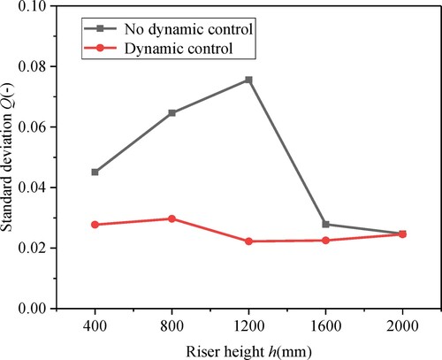
But it can be seen from Figures and that during the continuous rolling process of the RCFB, when the dynamic control method is not used for the RCFB, the whole process of particle concentration is higher with an uneven distribution in the riser. With the increase of riser height, particle concentration change is larger. In the case that the dynamic control method is used for the RCFB, the volume fraction of particles in the whole riser is significantly lower than that in the case of no dynamic control of the air distributor. Therefore, the dynamic control of the air distribution plate can effectively reduce the accumulation of particles in the riser of the RCFB, so that particles can be evenly distributed in the riser.
6. Conclusions
At the present work, a dynamic control method is proposed by using an air distribution plate with the aim of improving the distribution uniformity of particles within the RCFB. Numerically simulated approach which is called two-fluid flow model is able to be used to simulate the multiphase behaviors within the RCFB. The functional relation between six different tilt angles θ which are θ = 2°, 5°, 8°, 10°, 12° and 15° and eight different inclined angles φ which are φ = −2°, −5°, 0°, 2°, 5°, 8°, 10° and 12° is able to be clarified. In addition, a dynamic mesh model is applied to the RCFB, which is able to realize its rolling motion. Meanwhile, the correctness of the functional relation is also able to be verified. The conclusions are shown as follows:
In the case that the RCFB is in the fixed inclination state where six different θ (θ = 2°, 5°, 8°, 10°, 12° and 15°) are used, it is found that with the increase of θ, uneven distribution behaviors tend to be more serious for particles especially at the lower position of the RCFB’s riser. On a contrary, with the increase of θ, the differences of particles distribution behaviors at the top of the riser are seldom regardless of the variation of θ.
By adjusting the inclined angles φ of the air distribution plate where φ equals to −2°, −5°, 0°, 2°, 5°, 8°, 10° and 12°, the uneven phenomenon of particles distribution behaviors are able to be alleviated no matter how θ changes for the RCFB. In the case that θ equals to 2°, 5°, 8°, 10°, 12° and 15°, the corresponding φ is 2°, 8°, 10°, 12°, 8° and 5°, respectively.
A function relation between θ and φ is obtained through dynamic control method, which is verified by using the dynamic mesh model for the RCFB. There is a potential that the proposed function relation has the potential to increase the uniformity of the particles distribution behaviors within the RCFB.
Acknowledgements
The present study was supported by the National Natural Science Foundation of China (Grant No: 51876175) and the Technology Innovation Leading Program of Shaanxi, China (Program No. 2019CGXNG-030). The authors also would like to express their appreciation for simulation support from Miss. Ruibo Li.
Additional information
Funding
References
- Almuttahar, A., & Taghipour, F. (2008). Computational fluid dynamics of high density circulating fluidized bed riser: Study of modeling parameters. Powder Technology, 185(1), 11–23. https://doi.org/https://doi.org/10.1016/j.powtec.2007.09.010.
- Anantharaman, A., Issangya, A., Karri, S. B. R., Findlay, J., Hrenya, C. M., Cocco, R. A., & Chew, J. W. (2017). Annulus flow behavior of Geldart Group B particles in a pilot-scale CFB riser. Powder Technology, 305, 816–828. https://doi.org/https://doi.org/10.1016/j.powtec.2016.11.007
- Cai, R., Ke, X., Huang, Y., Zhu, S., Li, Y., Cai, J., Yang, H., Lyu, J., & Zhang, M. (2019). Applications of Ultrafine Limestone Sorbents for the Desulfurization Process in CFB Boilers. Environmental Science & Technology, 53(22), 13514–13523. https://doi.org/https://doi.org/10.1021/acs.est.9b04747
- Ghalandari, M., Bornassi, S., Shamshirband, S., Mosavi, A., & Chau, K. W. (2019). Investigation of submerged structures’ flexibility on sloshing frequency using a boundary element method and finite element analysis. Engineering Applications of Computational Fluid Mechanics, 13(1), 519–528. https://doi.org/https://doi.org/10.1080/19942060.2019.1619197
- He, Y., Bayly, A. E., & Hassanpour, A. (2018). Coupling CFD-DEM with dynamic meshing: A new approach for fluid-structure interaction in particle-fluid flows. Powder Technology, 325, 620–631. https://doi.org/https://doi.org/10.1016/j.powtec.2017.11.045
- He, Y., Bayly, A. E., Hassanpour, A., Fairweather, M., & Muller, F. (2020). Flow behaviour of an agitated tubular reactor using a novel dynamic mesh based CFD model. Chemical Engineering Science, 212, 115333. https://doi.org/https://doi.org/10.1016/j.ces.2019.115333.
- Hou, B., Wang, X., Zhang, T., & Li, H. (2017). A model for improving the Euler–Euler two-phase flow theory to predict chemical reactions in circulating fluidized beds. Powder Technology, 321, 13–30. https://doi.org/https://doi.org/10.1016/j.powtec.2017.07.081
- Huai, W.-x., Xue, W.-y., & Qian, Z.-d. (2012). Numerical Simulation of Sediment-Laden Jets in Static Uniform Environment using Eulerian Model. Engineering Applications of Computational Fluid Mechanics, 6(4), 504–513. https://doi.org/https://doi.org/10.1080/19942060.2012.11015438
- Jenaru, A., & Acomi, N. (2016). Numerical methods for assessment of the ship's pollutant emissions. In V. Cohal, L. Lobont, P. Topala, E. Oanta, M. Placzek, I. Carcea, C. Carausu, & D. Nedelcu (Eds.), Modtech International Conference – Modern Technologies in Industrial Engineering Iv, Pts 1-7 (Vol. 145). Iop Publishing Ltd. https://doi.org/https://doi.org/10.1088/1757-899x/145/8/082015.
- Ma, X. (2017). Analysis of the evolution mechanism about safety vulnerability of China's marine transport lanes. World Economics and Politics, 11, 108–129+159.
- Mnasri, C., Hafsia, Z., Omri, M., & Maalel, K. (2010). A Moving Grid Model for Simulation of Free Surface Behavior Induced by Horizontal Cylinders Exit and Entry. Engineering Applications of Computational Fluid Mechanics, 4(2), 260–275. https://doi.org/https://doi.org/10.1080/19942060.2010.11015315
- Mosavi, A., Shamshirband, S., Salwana, E., Chau, K.-w., & Tah, J. H. M. (2019). Prediction of multi-inputs bubble column reactor using a novel hybrid model of computational fluid dynamics and machine learning. Engineering Applications of Computational Fluid Mechanics, 13(1), 482–492. https://doi.org/https://doi.org/10.1080/19942060.2019.1613448
- Murata, H., Oka, H., Adachi, M., & Harumi, K. (2012). Effects of the ship motion on gas–solid flow and heat transfer in a circulating fluidized bed. Powder Technology, 231, 7–17. https://doi.org/https://doi.org/10.1016/j.powtec.2012.06.060
- Park, S., Yang, J., & Rhee, S. H. (2017). Parametric study on ship’s exhaust-gas behavior using computational fluid dynamics. Engineering Applications of Computational Fluid Mechanics, 11(1), 159–171. https://doi.org/https://doi.org/10.1080/19942060.2016.1260057
- Razvan, C., Lucian, G., & Ioan, M. (2015a). An OOP MATLAB Extensible Framework for the Implementation of Genetic Algorithms. Part I: The Framework. Procedia Technology, 19, 193–200. https://doi.org/https://doi.org/10.1016/j.protcy.2015.02.028
- Razvan, C., Lucian, G., & Ioan, M. (2015b). An OOP MATLAB Extensible Framework for the Implementation of Genetic Algorithms. Part II: Case Study. Procedia Technology, 19, 201–206. https://doi.org/https://doi.org/10.1016/j.protcy.2015.02.029
- Song, G., Li, Y., Wang, W., & Shi, Z. (2020). Numerical simulation of hydrate particle size distribution and hydrate particle bedding in pipeline flowing systems. Journal of Dispersion Science and Technology, 41(7), 1051–1064. https://doi.org/https://doi.org/10.1080/01932691.2019.1614043
- Tian, Y., & Peng, X. F. (2004). Analysis of particle motion and heat transfer in circulating fluidized beds. International journal of energy research, 28(4), 287–297. doi:https://doi.org/10.1002/er.965
- Wahyudi, H., Chu, K. W., & Yu, A. B. (2016). 3D particle-scale modeling of gas–solids flow and heat transfer in fluidized beds with an immersed tube. International Journal of Heat and Mass Transfer, 97, 521–537. https://doi.org/https://doi.org/10.1016/j.ijheatmasstransfer.2016.02.038
- Wang, Z., Zhao, T., Liu, K., & Takei, M. (2020). Clarification of an improved cluster renewal model (ICRM) for heat transfer characteristics in a rolling circulating fluidized bed (RCFB). Advanced Powder Technology, 31(7), 2866–2879. https://doi.org/https://doi.org/10.1016/j.apt.2020.05.015
- Wu, Y., Liu, D. Y., Ma, J. L., & Chen, X. P. (2017). Three-Dimensional Eulerian–Eulerian Simulation of Coal Combustion under Air Atmosphere in a Circulating Fluidized Bed Combustor. Energy & Fuels, 31(8), 7952–7966. https://doi.org/https://doi.org/10.1021/acs.energyfuels.7b01084
- Xia, Y., & Peng, F. F. (2007). Effect of Structured Plates on Fine Coal Gravity Separation in a Liquid Fluidized Bed System. Engineering Applications of Computational Fluid Mechanics, 1(3), 164–180. https://doi.org/https://doi.org/10.1080/19942060.2007.11015190
- Yan, L., Liu, H., Li, F., & Liu, J. (2020). Dynamic characteristics of the large particles inside the fluidized bed with an inclined air distribution plate. Powder Technology, 367, 632–642. https://doi.org/https://doi.org/10.1016/j.powtec.2020.03.069
- Zhang, M.-C. (2020). Characteristic-particle-tracked modeling for CFB boiler: Coal combustion and ultra-low NO emission. Powder Technology, 374, 632–647. https://doi.org/https://doi.org/10.1016/j.powtec.2020.07.079
- Zhang, H., Zhong, L., Chen, J., & Zhang, Y. (2016). Review on desulfurization and denitration technologies for ship exhaust gas treatment. Chemical Industry and Engineering Progress, 35(11), 3650–3657. https://doi.org/https://doi.org/10.16085/j.issn.1000-6613.2016.11.040
- Zhao, T., Liu, K., Murata, H., Harumi, K., & Takei, M. (2014). Experimental and numerical investigation of particle distribution behaviors in a rolling circulating fluidized bed. Powder Technology, 258, 38–48. https://doi.org/https://doi.org/10.1016/j.powtec.2014.03.023
- Zhao, T., Nakamura, Y., Liu, K., Murata, H., & Takei, M. (2016). The effect of rolling amplitude and period on particle distribution behavior in a rolling circulating fluidized bed. Powder Technology, 294, 484–492. https://doi.org/https://doi.org/10.1016/j.powtec.2016.03.018