
 ?Mathematical formulae have been encoded as MathML and are displayed in this HTML version using MathJax in order to improve their display. Uncheck the box to turn MathJax off. This feature requires Javascript. Click on a formula to zoom.
Abstract
It is important to optimize the structure of inlet due to the increasing demand of ram air. In this paper, structural optimization of the submerged inlet is pursued using a hybrid model by integrating least squares support vector machines (LS-SVM) prediction model and improved genetic algorithm-particle swarm optimization (GA-PSO). Inlet shape is controlled by changing three-dimensional geometric parameters. Ramp angle, width to depth ratio and ramp length play significant parts in this optimization process. Ram efficiency and mass flow are the main objectives of the performance evaluation. Results show that the prediction error of the mass flow and ram efficiency is 2.31% and 0.54%, respectively. Comparison with the original geometry is used to prove the optimization capabilities of the proposed optimization method. The mass flow and ram efficiency are increased by 29.2% and 10.0%, respectively. In addition, the characteristics of the optimized submerged inlet geometry are numerically investigated. The numerical results are compared to the optimization results and indicate that this optimization method has high validity. The error of ram efficiency and mass flow is 0.30% and 0.66%, respectively. Consequently, this optimization method can be valuable to aircraft engineers-by providing a novel approach for the design of the submerged inlet.
1. Introduction
Submerged inlet is an important component of the aircraft ram air system (Vargas & Bejan, Citation2001), which is used to provide fresh air and cold air for air conditioning system, auxiliary cooling system, etc., to create comfortable living and working environment for crew and passengers and ensure the stability and reliability of equipment (Wang et al., Citation2020). There are still some difficulties in the design process of the submerged inlet, because not only the constraints of the fuselage structure, but also the high aerodynamic performance of the inlet should be considered (Wang et al., Citation2016).
Early studies on submerged inlet were mainly conducted by National Advisory Committee for Aeronautics. Mossman and Randall (Citation1948) studied the effects of different geometric parameters on pressure recovery of a submerged inlet. The experimental data indicated that a submerged inlet with curved-divergent ramp walls, a 5° to 7° ramp angle, and a width to depth ratio from 3 to 5 shows the best characteristics. Besides, mass flow ratio was found to have a considerable effect on pressure recovery (Sun & Guo, Citation2005), but variations of Mach number, in general, caused a small effect on pressure recovery (Axelson & Taylor, Citation1950; Selna & Schlaff, Citation1951). Also, Hall and Barclay (Citation1948) studied the influence of inlet location on its aerodynamic performance.
Nowadays, with the development of science and technology, an optimization tool is widely used in various fields. Guo and Lu (Citation2003) presented a design optimization method based on GA and BP network to optimize the engine disk with nine structural parameters. Jiang et al. (Citation2008) and Li et al. (Citation2010) developed an optimization program based on a programming language by combining computational fluid dynamic software and optimization procedure for inlet design. Baghban et al. (Citation2019) developed an adaptive network-based fuzzy inference system (ANFIS) for estimating the relative viscosity of nanofluids. Ghalandari et al. (Citation2019) introduced an optimization method based on genetic algorithm, artificial neural networks and design of experiments to optimize the first blade of a new test rig. Li et al. (Citation2020) took advantage of the optimization method based on BP neural network and genetic algorithm to generate the optimum shape of the submerged inlet.
The previous studies were mainly focused on engines and transonic or supersonic flights. Researches on the aircraft submerged inlet are rare. Although Li et al. (Citation2020) has presented an optimization method, the genetic algorithm has some shortcomings, such as the lack of local search ability and strong dependence on the initial population. Considering these problems, a new optimization method integrating LS-SVM prediction model and improved GA-PSO approach is proposed to optimize the aircraft submerged inlet. Ramp angle, width to depth ratio and ramp length are the key factors to be considered in this optimization process. Ram efficiency and mass flow are the main limitations. After optimization, the characteristics of the optimized submerged inlet geometry are numerically investigated to validate the reliability of the optimization method.
2. Numerical method validation
2.1. Computational domain and boundary conditions
All data samples are generated by numerical method coupling with ANSYS 18.0 software. It is necessary to validate the reliability of the numerical method. The validation model is DLR-F6 model (Laflin et al., Citation2005; Roy et al., Citation2018), which has been tested experimentally by Drag Prediction Workshop (DPW).
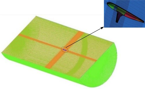
The computational domain is meshed using the structured grid generated by the pre-processor ICEM, as shown in Figure . The computational domain is divided into two sub-domains. In the far field zone, the sub-domain is relatively coarse. The sub-domain is very dense around the DLR-F6 model. The boundary conditions are consistent with the officially published design conditions.
Figure 1. Schematic diagram of the grids.
2.2. Turbulence model
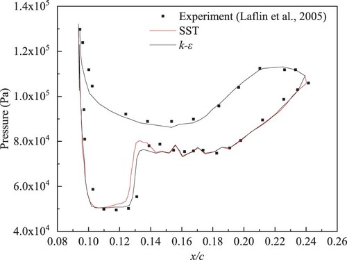
In order to eliminate the effects of turbulence model on the computational results, an appropriate turbulence model is crucial to simulate the flow. Figure shows the effects of SST and k-ε turbulence models on the surface pressure distribution of the wing with x/c, where x is the distance from the front edge of the wing, c is the chord length of the wing. As shown in Figure , the k-ε turbulence model shows better agreement with the experimental results for the surface pressure distribution of the wing than the SST turbulence model. Therefore, the k-ε turbulence model is adopted in this work.
Figure 2. Surface pressure distribution of the wing.
2.3. Number of grids
Table shows the effects of different grid numbers on the simulation results under the same simulation conditions, and the number of grids is 6.3 million, 11 million, 19 million and 29 million respectively.
Table 1. Comparison of experimental results and simulation results.
In Table , CL is lift coefficient, CD is drag coefficient. It can be seen from Table that when the number of grids is above 11million, the drag coefficient remains unchanged, and the error is about 1%. At this time, the increasing number of grids has little effects on the calculation results. Besides, the more the number of grids, the longer the computing time. Therefore, 11 million is selected for subsequent numerical simulations.
3. Optimization method based on LS-SVM and improved GA-PSO approach
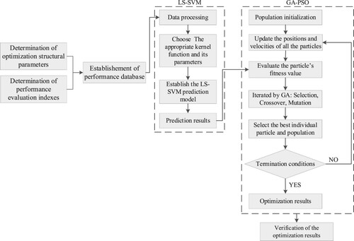
In this paper, a new method of structural parameters optimization is demonstrated by integrating LS-SVM prediction model and improved GA-PSO algorithm. The flowchart for its usage is shown in Figure . As shown in Figure , this optimization method contains four stages: establishing performance database, establishing prediction model, establishing optimization model and verifying the optimization results. The LS-SVM prediction model is used to predict the performance of the aircraft submerged inlet, and the improved GA-PSO algorithm is used to find the optimal results. The prediction results are used to evaluate the particle’s fitness value.
Figure 3. Flowchart of the optimization method.
3.1. Structural parameters
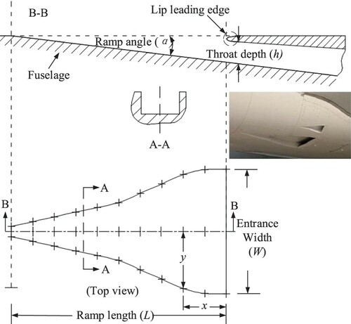
Before structural design optimization, the structural parameters of the submerged inlet must be obtained. Figure shows the practicality picture and structure diagram of the aircraft submerged inlet. A-A and B-B is the sectional views of the position shown in the top view. The key structural parameters affecting its performance are ramp angle (α), width to depth ratio (Awh) and ramp length (L).
Figure 4. Practicality picture and structure diagram of the aircraft submerged inlet.
3.2. Performance evaluation indexes
In this paper, in addition to the selection of mass flow, ram efficiency is also chosen as the evaluation index of the submerged inlet aerodynamic performance. Ram efficiency reflects the energy loss of free flow induced into the submerged inlet, which is a significant index for performance evaluation of the submerged inlet. It is defined as the ratio of dynamic pressure at inlet throat to free flow dynamic pressure, and can be written as:
(1)
(1) where αp is the ram efficiency,
is the total pressure at the inlet throat,
is the total pressure of ambient,
is the static pressure of air flow.
3.3. Performance database
The quantity of data samples has a great influence on the accuracy of the prediction model. Given that the above three structural parameters each taking six values, ending with a total numerical simulation model of 216. The values of structure parameters are listed in Table .
Table 2. Values of structure parameters.
In this paper, numerical simulation of the above 216 models are performed, and the performance database within the range of the above structural parameters is formed. Further, Figures show the relationship between performance evaluation indexes and structural parameters.
Figure 5. Ram efficiency vs. width to depth ratio and ramp length (ramp angle = 6°).
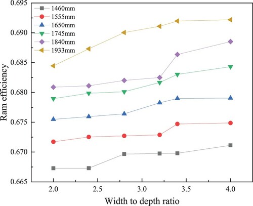
Figure 6. Ram efficiency vs. width to depth ratio and ramp angle (ramp length = 1460 mm).
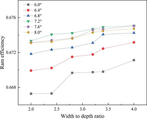
Figure 7. Mass flow vs. width to depth ratio and ramp length (ramp angle = 6°).
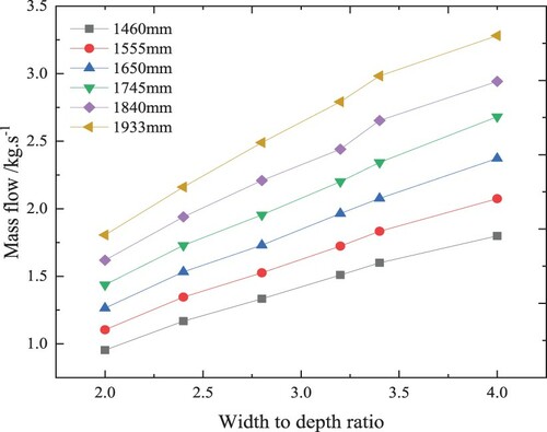
Figure 8. Mass flow vs. width to depth ratio and ramp angle (ramp length = 1460 mm).
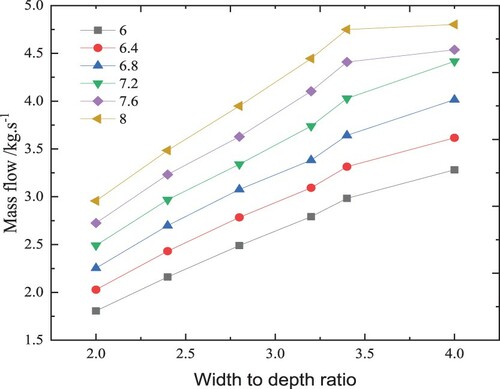
As shown in Figures , ram efficiency and mass flow exhibit a monotonous change with structural parameters, and its curvature does not seem to be fixed or constant. Specially, when ramp angle is large, the curve of ram efficiency and mass flow variation level out when width to depth ratio is greater than 3.5.
3.4. LS-SVM prediction model
LS-SVM was first proposed by Suykens and Vandewalle (Citation1999). It is an extended form of standard SVM (Hearst et al., Citation1998). In LS-SVM, the original data can be mapped to a high-dimensional space by non-linear mapping (Kim et al., Citation2011), in which linear regression is then conducted by least square method (Axelsson, Citation1987) to obtain a fitting function. Because of the excellent generalization ability, it was extensively used to solve linear and nonlinear regression problems (Liu et al., Citation2018).
Here, the mapping relationship between input variables and output variables is established, and the mapping function can be described as:
(2)
(2) where M is the designed mass flow.
A normal LS-SVM regression model is described as:
(3)
(3) where x is the input variables, y(x) is the output variables, αi is the multipliers of Lagrange function in dual space, b is a paranoia, K (x, xi) is the kernel function matrix of LS-SVM model, N is the dimension of K (x, xi).
The kernel function is vital for data processing speed and prediction accuracy of LS-SVM prediction model. Here, Gaussian kernel function (Fritzke, Citation1994) is used to develop the LS-SVM prediction model.
(4)
(4)
The relationship between the kernel function and the mapping function is described as:
(5)
(5)
In this work, ramp angle (α), width to depth ratio (Awh) and ramp length (L) are used as input variables, mass flow ratio (M) and ram efficiency (αp) are used as output variables, with a total of 216 data samples from the performance database.
Each time, the prediction model is trained with 171 data samples and tested with remaining 45 data samples. The results are shown in Figures and .
Figure 9. The predicted ram efficiency values vs. the actual ram efficiency values.
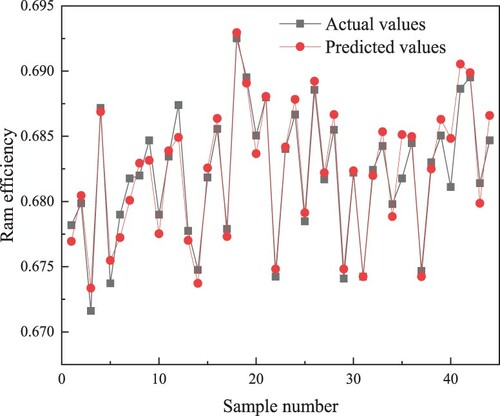
Figure 10. The predicted mass flow values vs. the actual mass flow values.
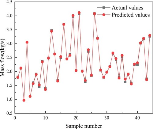
For a more intuitive analysis of the prediction accuracy, Table shows the mean relative error (MRE) and the mean squared error (MSE) of ram efficiency and mass flow respectively.
Table 3. Prediction accuracy of LS-SVM prediction model.
According to Table , the values of MRE and MSE are relatively small, indicating that the accuracy of the proposed LS-SVM prediction model is enough.
3.5. Improved GA-PSO approach
The mapping relationship between input variables and output variables has been constructed by the LS-SVM prediction model, but there is no specific function expression for it, so it is not easy to obtain the optimal results via classical optimization approaches. Due to the characteristics of self-organization, self-adaptive, self-learning and random search optimization, the intelligent optimization algorithm has been widely used for solving global optimization issues without specific function expressions.
GA (Lee & Hsiao, Citation2011; Park et al., Citation2020) and PSO (Han et al., Citation2018) are two common algorithms used in the artificial intelligence field. GA creates new individuals using crossover and mutation as well as selection of the best individuals from the current population, and uses them as parents to produce offspring for the next generation (Shin et al., Citation2018). PSO is a population-based optimization algorithm in search for the best solution by simulating the movement of a flock of birds (Xiong et al., Citation2019). These algorithms have advantages and disadvantages. Therefore, in this paper, the two algorithms are combined to perform structural parameters optimization. Several improvements to the original GA-PSO approach have been made to improve the optimization accuracy, convergence speed and search capability.
Self-adaptive attenuation strategy of inertia weight factor. In traditional PSO algorithms, the inertia weight factor is determined through a direct assignment method. The inertia weight factor that is too large or too small may reduce the search accuracy. Thus, the self-adaptive attenuation strategy of inertia weight factor is adopted, as shown in the following equation (Chen et al., Citation2006):
(6)
Similarly, the inertia weight factor should be contained in the equation below to improve the accuracy of particles speed updating (Hou et al., Citation2008):
(7)
(7) where V is the position vector, Vi represents the velocity of the ith particle, c1 and c2 are constant factors used to adjust the relative importance of Pi and Pg, Pi is the optimal solution found by the ith particle, Pg is the optimal solution found by the population, rand() is used to generate random numbers between 0 and 1, X is the velocity vector, Xi is the position of the ith particle, t represents the current particle.
The formula of particle position updating is shown in the below equation (Hu, Citation2017):
(8)
(8)
Selection for particles preference. Particles are ranked according to the performance following its fitness. Then the first 1/3 is selected for subsequent iterations to ensure the superiority of population evolution and speed up the optimization process. The particles position of the offspring can be calculated by the following two equations (Shola & Bolaji, Citation2016):
Similarly, the particles speed of the offspring can be calculated by the following two equations:
(11)
(11)
(12)
(12) where t’ represents the nascent progeny particle and V1(t) and V2(t) represent the velocity of its two parents, X1(t) and X2(t) represent the position of its two parents.
When crossed, the middle 1/3 of the previous generation is replaced by offspring particles, and last 1/3 of the previous generation are randomly reassigned by the remaining offspring particles.
In this paper, the structural parameters optimization is done with the target of maximum ram efficiency under the premise of meeting designed mass flow. The mathematical model of the improved GA-PSO algorithm can be expressed as the following equations:
(13)
(13)
(14)
(14)
4. Results and discussions
4.1. Baseline configuration
ESDU 86002 (Engineering Sciences Data Unit, Citation1996) introduces two structural design methods of the aircraft submerged inlet: based on maximum mass flow and based on maximum efficiency. This paper mainly studies the effect of different structural parameters on ramp efficiency, so the design scheme based on maximum efficiency is chosen. The design process is shown in Figure .
Figure 11. Design process based on maximum efficiency.

In Figure , ρ is the density of free flow. V is the velocity of free flow, θ is the momentum boundary layer thickness where the aircraft submerged inlet installed, h is the throat depth of the aircraft submerged inlet.
The typical cruise conditions of a certain aircraft are selected as the design point to generate the baseline configuration. The parameters of design point are shown in Table .
Table 4. Parameters of the design point.
According to Table , dimensions of the key structural parameters of aircraft the submerged inlet are obtained, of which ramp angle (α) is 7°, width to depth ratio (Awh) is 2, and ramp length (L) is 1300 mm. Take this configuration as a baseline configuration. The numerical simulation result of mass flow is 1.787 kg/s and ram efficiency is 0.6254. However, it is worth noting that the mass flow is less than the designed mass flow. The main reason for this is that the above design method is semi-empirical. The design method is based on a theoretical calculation of two-dimensional boundary layer characteristics, and is modified by the available experimental data.
Further, Figure shows the velocity streamline of the aircraft submerged inlet.
Figure 12. Velocity streamline of the aircraft submerged inlet. (a) Velocity streamline of external flow field. (b) Velocity streamline of internal flow field.
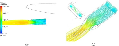
As can be seen from Figure , the flow field is uniform before the entrance of the inlet. The phenomenon of flow separation appears inside the inlet duct, along with the higher velocity in the central area and lower velocity near both sides of the duct wall. And there is a pair of vortices generated on the outlet plane, which induced more air into the inlet duct. Besides, the direction of velocity streamline of external flow field is not parallel to that of inlet axis, leading to an asymmetric distribution of vortices.
4.2. Optimization results
Different from the single-objective optimization, the elements in the optimal solution set of multi-objective optimization problems are often incomparable, and even the improvement of one objective is at the cost of the performance degradation of other objectives. Therefore, there is no unique optimal solution for multi-objective optimization problems, but a set of multiple satisfactory solutions, which is generally called Pareto optimal solution set. Figure shows the three best solutions.
Figure 13. Parteo diagram of optimization results.
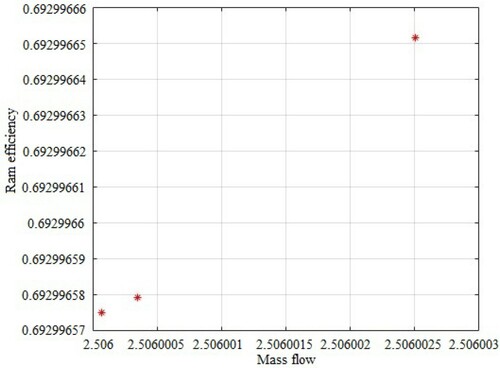
As shown in Figure , the final optimization results are constituted of three solutions, as given in Table .
Table 5. Optimization results.
As can be seen from Table , the three solutions are very close. It is suggested that the three solutions could be considered same when only the first decimal place is employed. Thus, the final optimization results are: Awh = 2.8, α = 6.2, L = 1912.5 mm, along with M = 2.5060 kg/s, αp = 0.692996.
To validate the reliability and accuracy of this study, a numerical simulation is conducted based on the optimization results presented above, and the results are listed in Table .
Table 6. Performance of baseline model and optimized model.
As shown in Table , the optimization results are quite consistent with the simulation results. The error of mass flow and ram efficiency is 0.66% and 0.30%, respectively, which gives credibility to the results within the error tolerance. Besides, the performance of the aircraft submerged inlet is apparently improved after optimization. The increase is by 29.2% in mass flow and 10.0% in ram efficiency.
5. Conclusions
An optimization method based on LS-SVM and impro-ved GA-PSO approach of the design of the aircraft submerged inlet is proposed. Ramp angle, width to depth ratio and ramp length play significant parts in this optimization process. Ram efficiency and mass flow are set as the main optimization objectives. Inlet geometry is optimized to have the best aerodynamical performance. Results show that the prediction error of the mass flow and ram efficiency is 2.31% and 0.54%, respectively. After optimization, the mass flow and ram efficiency are increased by 29.2% and 10.0%, respectively. In addition, comparisons with the numerical results obtained from the optimized submerged inlet geometry is used to verify the optimization results. The error of ram efficiency and mass flow is 0.30% and 0.66%, respectively. Consequently, this optimization method can be valuable to aircraft engineers-by providing a novel approach for the design of the aircraft submerged inlet. For further investigations, more artificial intelligence methods such as convolutional neural networks and gradient descent optimization algorithms can be used and compared with results obtained by the optimization method in this work.
Acknowledgements
The authors would like to thank Boyu Wu, Changdong Chen, for their support.
Disclosure statement
No potential conflict of interest was reported by the author(s).
Additional information
Funding
References
- Axelson, J. A., & Taylor, R. A. (1950). Preliminary investigation of the transonic characteristics of an NACA submerged inlet (Report No. A50C13). NACA.
- Axelsson, O. (1987). A generalized conjugate gradient, least square method. Numerische Mathematik, 51(2), 209–227. https://doi.org/https://doi.org/10.1007/BF01396750
- Baghban, A., Jalali, A., Shafiee, M., Ahmadi, M. H., & Chau, K.-W. (2019). Developing an ANFIS based swarm concept model for estimating relative viscosity of nanofluids. Engineering Applications of Computational Fluid Mechanics, 13(1), 26–39. https://doi.org/https://doi.org/10.1080/19942060.2018.154-2345
- Chen, G. M., Jia, J. Y., & Han, Q. (2006). Study on the strategy of decreasing inertia weight in particle swarm optimization algorithm. Journal of Xian Jiaotong University, 40(1), 53–56 + 61. https://doi.org/https://doi.org/10.1109/ICNC.2008.533
- Engineering Sciences Data Unit. (1996). Drag and pressure recovery characteristics of auxiliary air inlets at subsonic speeds [Data set]. ESDU.
- Fritzke, B. (1994). Fast learning with incremental RBF networks. Neural Processing Letters, 1(1), 2–5. https://doi.org/https://doi.org/10.1007/BF02312392
- Ghalandari, M., Ziamolki, A., Mosavi, A., Shamshirband, S., Chau, K.-W., & Bornassi, S. (2019). Aeromechanical optimization of first row compressor test stand blades using a hybrid machine learning model of genetic algorithm, artificial neural networks and design of experiments. Engineering Applications of Computational Fluid Mechanics, 13(1), 892–904. https://doi.org/https://doi.org/10.1080/19942060.2019.1649196
- Guo, H. D., & Lu, Z. F. (2003). Structure design optimization based on BP-neural networks and genetic algorithms. Jouranl of Aerospace Power, 18(2), 216–220. https://1d5ceec93f01d37405206751e45905a3
- Hall, C. F., & Barclay, F. D. (1948). An experimental investigation of NACA submerged inlets at high subsonic speeds I: Inlets forward of the wing leading edge (Report No. A8B16). NACA.
- Han, H. G., Lu, W., & Qiao, J. F. (2018). A multi-objective particle swarm optimization algorithm based on the diversity information and convergence degree. Acta Electronica Sinica, 46(2), 315–324. https://doi.org/https://doi.org/10.3969/j.issn.0372-2112.2018.02.009
- Hearst, M. A., Dumais, S. T., Osman, E., & Platt, J. C. (1998). Support vector machines. IEEE Intelligent Systems, 13(4), 18–28. https://doi.org/https://doi.org/10.1109/5254.708428
- Hou, Y. L., Zhao, C. H., & Hu, J. W. (2008). Fault test set optimization based on particle swarm optimization algorithm. Journal of Electronic Measurement and Instrument, 22(4), 21–25. https://doi.org/https://doi.org/10.13382/j.jemi.2008.04.010
- Hu, J. (2017). Effect on convergence from different particle swarms with a unified and simplified formula for position updating. 2017 9th International Conference on Intelligent Human-Machine Systems and Cybernetics (IHMSC) (pp. 228–232). IEEE.
- Jiang, A. P., Huang, J. T., Wang, J., Ding, Q., & Huang, G. H. (2008). Optimal design of intake system mufflers in engine based on single and multi-objective optimization. 2008 7th World Congress on Intelligent Control and Automation (pp. 8733–8737). IEEE.
- Kim, S. Y., Moon, S. K., Jung, D. C., & Hwang, S. I. (2011). Pre-operative prediction of advanced prostatic cancer using clinical decision support systems: Accuracy comparison between support vector machine and artificial neural network. Korean Journal of Radiology, 12(5), 588–594. https://doi.org/https://doi.org/10.3348/kjr.2011.12.5.588
- Laflin, K. R., Klausmeyer, S. M., Tom, Z., Vassberg, J., Wahls, R. A., Morrison, J. H., Brodersen, O., Rakowitz, M., Tinoco, E. N., & Godard, J.-L. (2005). Data summary from second AIAA computational fluid dynamics drag prediction workshop. Journal of Aircraft, 42(5), 1165–1178. https://doi.org/https://doi.org/10.2514/1.10771
- Lee, W.-P., & Hsiao, Y.-T. (2011). An adaptive GA-PSO approach with gene clustering to infer S-system models of gene regulatory networks. The Computer Journal, 54(9), 1449–1464. https://doi.org/https://doi.org/10.1093/comjnl/bxr038
- Li, Z. M., Chen, C. D., Pei, H. J., & Kong, B. B. (2020). Structural optimization of the aircraft NACA inlet based on BP neural networks and genetic algorithms. International Journal of Aerospace Engineering, 2020(2), 1–9. https://doi.org/https://doi.org/10.1155/2020/8857821
- Li, S. Z., Shuo, T., & Gao, D. (2010). An integrated optimization for hypersonic inlet design based on PYTHON. 2010 International Conference on Computer Design and Applications (pp. V4-64–V4-67). IEEE.
- Liu, X., Liu, F., Huang, W. H., Peng, J. Y., Shen, T. T., & He, Y. (2018). Quantitative determination of Cd in soil using laser-induced breakdown spectroscopy in air and Ar conditions. Molecules, 23(10), 2492–2496. https://doi.org/https://doi.org/10.3390/molecules23102492
- Mossman, E. A., & Randall, L. M. (1948). An experimental investigation of the design variables for NACA submerged duct entrances (Report No. A7130). NACA.
- Park, D., Cha, J., Kim, M., & Go, J. S. (2020). Multi-objective optimization and comparison of surrogate models for separation performances of cyclone separator based on CFD, RSM, GMDH-neural network, back propagation-ANN and genetic algorithm. Engineering Applications of Computational Fluid Mechanics, 14(1), 180–201. https://doi.org/https://doi.org/10.1080/19942060.2019.1691054
- Roy, C. J., Rumsey, C. L., & Tinoco, E. N. (2018). Summary of data from the sixth AIAA CFD drag prediction workshop: Code verification. Journal of Aircraft, 55(4), 1338–1351. https://doi.org/https://doi.org/10.2514/1.C034856
- Selna, J., & Schlaff, B. A. (1951). An investigation of the drag and pressure recovery of a submerged inlet and a nose inlet in the transonic flight range with free-fall models (Report No. A51H20). NACA.
- Shin, S. Y., Müller, A., Verma, N., & Lev, S. (2018). Systems modelling of the EGFR-PYK2-c-Met interaction network predicts and prioritizes synergistic drug combinations for triple-negative breast cancer. PLoS Computational Biology, 14(6), e1006192. https://doi.org/https://doi.org/10.1371/journal.pcbi.100-6192
- Shola, P., & Bolaji, A. L. (2016). An algorithm for continuous optimization problems using hybrid particle updating method. Indonesian Juornal of Electrical Engineering and Computer Science, 3(1), 164–173. https://doi.org/https://doi.org/10.11591/ijeecs.v3.i1.pp164-173
- Sun, S., & Guo, R. W. (2005). Numerical analysis and experimental validation of a submerged inlet on the plane surface. Chinese Journal of Aeronautics, 18(3), 199–205. https://doi.org/https://doi.org/10.1016/S1000-9361(11)60298-7
- Suykens, J. K., & Vandewalle, J. (1999). Training multilayer perceptron classifiers based on a modified support vector method. IEEE Transaction on Neural Networks, 10(4), 907–911. https://doi.org/https://doi.org/10.1109/72.774254
- Vargas, J. V. C., & Bejan, A. (2001). Thermodynamic optimization of finned crossflow heat exchangers for aircraft environmental control systems. International Journal of Heat Fluid Flow, 22(6), 657–665. https://doi.org/https://doi.org/10.1016/S0142-727X(01)00129-1
- Wang, Y., Li, Z. M., Pei, H. J., Cui, Y. L., Chen, C. D., & Wu, B. Y. (2020). Research advances of ram air intake of civil aircraft. Aviation Precision Manufacturing Technology, 56(1), 31–35 + 39. https://doi.org/https://doi.org/10.1007/s12541-019-00202-0
- Wang, Y. G., Wang, C. H., Xiao, Y. C., Chen, B., Zhou, S., Guo, J. T., & Sun, M. W. (2016). Construction methodology for lip surface of a submerged inlet. Aerospace Science and Technology, 54, 340–352. https://doi.org/https://doi.org/10.1016/j.ast.2016.04.029
- Xiong, Y., Ling, Q. H., Han, F., & Liu, Q. H. (2019). An efficient gene selection method for microarray data based on LASSO and BPSO. BMC Bioinformatics, 20(S22), 1–13. https://doi.org/https://doi.org/10.1186/s12859-019-3228-0