
 ?Mathematical formulae have been encoded as MathML and are displayed in this HTML version using MathJax in order to improve their display. Uncheck the box to turn MathJax off. This feature requires Javascript. Click on a formula to zoom.
Abstract
This study numerically investigates the combustion characteristics in a swirl burner for CO-H2 syngas by large eddy simulation. Firstly, experimental data are used to verify the applicability of the Boivin mechanism and the Sandia mechanism. The simulation results show that the Boivin mechanism predicts a more reasonable flame structure. Then, Syngas25, Syngas45, and Syngas100 (composed of 25%, 45%, and 100% H2 by volume, respectively) are set to numerically investigate the effect of hydrogen addition ratio on combustion characteristics by using the dynamic Smagorinsky model and the partially stirred reactor model. The detailed simulation data shows that the addition of hydrogen greatly influences the flame structure and flow field; with an increase in hydrogen addition, the flame length shortens, the temperature rises, and flashback caused by combustion induced vortex breakdown occurs. Furthermore, the precessing vortex core cannot exist stably in Syngas100, though it can be clearly observed in other cases.
Nomenclature list
| = | Density | |
| = | Time | |
| = | Component of velocity vector in the i direction, i= 1, 2, 3. | |
| = | Component of spatial coordinate in the i direction, i= 1, 2, 3. | |
| = | Pressure | |
| = | Stress tensor | |
| = | Subgrid shear stress tensor | |
| = | Mass fraction of the species s | |
| = | Source term of the species s | |
| = | Energy source term | |
| = | Mass diffusion coefficient of the species s | |
| = | Subgrid viscosity | |
| = | Subgrid kinetic energy | |
| = | Rate-of-strain tensor | |
| = | Sub-grid fluxes of species | |
| = | Enthalpy | |
| = | Mass fluxes | |
| = | Temperature | |
| = | Sub-grid fluxes of energy | |
| = | Swirl number | |
| = | Equivalence ratio | |
| = | Subgrid kinematic viscosity | |
| = | Turbulent Prandtl number | |
| = | Turbulent Schmidt number | |
| = | Global reaction rate in the PaSR model | |
| = | Unrevised global reaction rate | |
| = | Chemical time scale | |
| = | Turbulent time scale | |
| = | Kinematic viscosity | |
| = | Mesh scale | |
| = | Laminar flame speed | |
| = | Total energy | |
| = | Lewis number | |
| = | Reynolds number | |
| = | Karlovitz number | |
| = | Courant–Friedrichs-Lewy number | |
| = | Diameter of center body | |
| = | Diameter of cylindrical combustion chamber | |
| = | cycle time of swirling |
1. Introduction
Despite the supply of energy by using different low-cost resources with lower carbon footprints is an on-going research interest (Eivaz et al., Citation2018), the major global energy supply still depend on fossil fuels (Jafari-Sejahrood et al., Citation2019). With the environmental protection regulations for power plants becoming increasingly stringent in recent years (Issakhov et al., Citation2020), integrated gasification combined cycle (IGCC) using coal gasification fuel and gas turbines has received much research attention due to its low emissions and high efficiency (E.O. Oluyede, Citation2007). The coal gasification fuel called syngas is a mixture of H2, CO, N2, and other minor constituents. Depending on the coal producer and gasification process, the relative proportion of H2 and CO can vary widely. The changeable fraction ratio thus induces variable combustion characteristics for syngas.
H2-CO syngas has a low volumetric heating value, about a third of methane (S. Taamallah et al., Citation2015). H2, one of the main components of syngas, has high gravimetric heating value and little pollution released from its combustion (in the presence of sufficient oxygen) that produces only water and energy (Faizollahzadeh Ardabili et al., Citation2018). Most hydrogen is currently produced via steam reforming of natural gas. As a fuel, hydrogen leads to major operability concerns in premixed combustion, because it is different from standard fuels on chemical and transport properties (S. Taamallah et al., Citation2015).
Among available fuels, hydrogen stands out in terms of its transport properties. Heat and momentum diffusivity for hydrogen are over six times larger than that for CH4, CO, and air, and mass diffusivity for hydrogen in air is about four times larger than CH4 and CO in air. CH4 and CO have similar transport properties, but different densities (S. Taamallah et al., Citation2015). Thus, CO-H2 syngas should exhibit different combustion properties compared with CH4 and CO.
Wang et al. (Citation2009) found that using hydrogen, especially pure hydrogen, in fuel mixtures is prone to severe flashback. However, when CH4 is added to H2, flashback probability becomes lower. Daniele et al. (Citation2009) concluded that in gas turbine, compared with natural gas, hydrogen-rich syngas are characterized by higher burning rates and, consequently, higher flashback propensity.
The Lewis number (Le) is defined as the ratio of thermal diffusivity to mass diffusivity (Abadi et al., Citation2020); for fuels with a small Le, the chemical energy contributed by the mass diffusion to the reaction zone is much higher than the energy lost from the reaction zone due to thermal diffusion, resulting in the formation of a local high reactant concentration zone and high temperature zone in the flow field (Fu et al., Citation2014). This phenomenon is caused by preferential diffusion. Park et al. (Citation2009) analysed the effect of preferential diffusion on temperature for non-premixed flames of syngas and found that chemical reactions are closely related to the formation of a local temperature distribution in the flow field. Bazooyar and Darabkhani (Citation2019) studied premixed hydrogen flame stabilization in a micro-combustor, and evaluated effect of preferential transport of species. Daniele et al. (Citation2011) successfully investigated the influence of the hydrogen concentration of syngas on turbulent burning velocity on the basis of OH-PLIF data. The results confirmed that hydrogen addition raises the turbulent-to-laminar flame speed ratio at the same turbulent level, for preferential diffusive-thermal effects.
In burning syngas in a swirling premixed chamber, the flow and combustion characteristics are important for chamber performance and should thus be investigated systemically. Using large eddy simulation (LES) to study combustion chambers has become an important auxiliary design method for the combustion chambers of gas turbines. In the LES method, the large-scale eddies are resolved directly while the small-scale eddies are modeled, so that the dominant vortex structures in the turbulence flow can be computed with limited computational expense (XSun et al., Citation2020). LES can reduce the number of experimental conditions, reduce the time and resource cost of experiments, and obtain data that are otherwise difficult to acquire in experiments. In addition, it can capture the dynamic process of the interaction between combustion and turbulence. Huang used LES in studying the dynamic combustion processes in a conventional swirling chamber that burns methane (Huang & Yang, Citation2009). The results revealed that the precessing vortex core (PVC) strongly affects the flow and flame evolution in combustion systems. Zheng et al. (Citation2013) performed an LES of the premixed swirling combustion of syngas by using reduced chemistry based on the Sandia mechanism. Their study revealed that the hydrogen concentrations of syngas does not affect the characteristic frequencies of the hydrodynamic instabilities. De and Acharya (Citation2012b) found that an LES-based artificially thickened flame model, even with simplified chemistry (3 reactions/6 species), is capable of predicting the behavior of 30% hydrogen-addition methane flame in a swirl burner. Another research by De and Acharya (Citation2012a) showed that high hydrogen content in CH4-H2 syngas makes the central toroidal recirculation zone (CTRZ) compact, leading to flashback for hydrogen has the high diffusivity and reactivity. Combustion-induced vortex breakdown (CIVB) was the main reason for the flashback observed numerically.
The behavior of CIVB depends on several factors, including the location of vortex breakdown, the inlet temperature, and axial velocity (Tangermann et al., Citation2010). Dam et al. (Citation2011) experimentally investigated the flashback mechanism caused by CIVB. Syngas with various compositions and different swirl numbers were analyzed. The results indicated that flashback is more sensitive to fuel composition. Under the same air flow and swirl number, syngas with higher H2 fraction leads to flashback at considerably lean conditions.
Although extensive investigations into premixed hydrogen-rich syngas using LES have been performed, most studies focused on CH4-H2 syngas. The current research on the effect of hydrogen addition on the combustion characteristics of CO-H2 syngas has not fully taken advantages of LES, that is, obtaining instantaneous results. As CIVB occurs primarily in swirl-stabilized combustors without a center body (Tangermann et al., Citation2010), the number of studies using LES on flashback caused by CIVB in combustors with center body is limited. The objective of this study is thus to numerically investigate the effect of hydrogen addition ratio in CO-H2 syngas on combustion characteristics via LES.
2. Flow configuration
2.1. Experimental device
To study the syngas flame in a swirl burner on the basis of different reaction mechanisms, this study used a baseline case with a steady inflow and experimental data for simulation validation. A new swirl burner designed by (Wang et al., Citation2016; Yu et al., Citation2013) was used to study the combustion characteristics. The burner called arrayed-vanes combustor is composed of an arrayed-vanes premixer and a chamber.
The arrayed-vanes combustor was experimentally studied by Yu et al. (Citation2013). In the experiment, the arrayed-vanes premixer was assembled on a cylindrical chamber made of quartz glass, which facilitated the optical measurement. A typical operating condition of the combustor was set using syngas fuel, and the operating condition under this base case is summarized in Table . Under the current condition, the global equivalence ratio φ = 0.29, and the swirl number S = 0.54.
Table 1. Operating condition of the experiment.
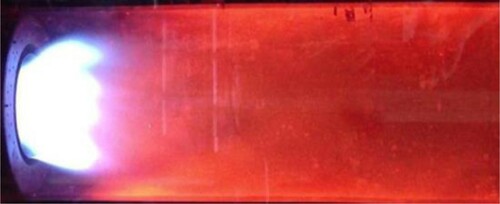
In the experiment, the combustion proceeded stably without flashback or blow out. The time-averaged temperature in the center of the outlet of the chamber was 1,393 K, which was measured by a thermocouple. The image of the flame in the chamber was captured by a digital camera (Figure ). The mean flame length in the chamber was about 82 mm, which was measured by scaling the luminous area with the chamber size in the picture. However, given the difficulty of obtaining optical measurements in such a complicated chamber, the details of the distribution of the flow variables were not obtained. The dynamic combustion processes and the interaction between the flame and turbulent vortexes could not be obtained either. Thus, the LES of the swirl burner was conducted in the current work to reveal the complex process in the chamber. The accuracy of the results of the simulation was validated by the experimental data.
Figure 1. Flame image in experiment.
2.2. Computational domain
Since no reaction occurs in the complex arrayed-vanes premixer, to accelerate the computation process, we simulated the arrayed-vanes premixer and the chamber individually (Figure ). LES of the premixer was firstly conducted, the simulation collected timing sequence data after achieving full development, including velocity, temperature, and species concentration on the premixer outlet plane. These data, which contain details of the outflow of the premixer, were used as the inlet boundary condition for the chamber. A similar approach was used successfully by (Tangermann et al., Citation2010; Tangermann & Pfitzner, Citation2008), who adopted a steady profile of velocity as the inlet boundary condition. By contrast, the dynamic inlet boundary condition adopted in the present research is more reasonable compared with the steady inlet boundary condition, because it can obtain the turbulence structure.
Figure 2. Computational domains of (a) premixer and (b) combustion chamber.
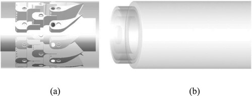
On the other hand, for simulating the combustion characteristics in the chamber, the computation domain for the LES encompasses an inflow passage with a diameter of 100 mm and a length of 50 mm and a cylindrical combustion chamber with a diameter of 210 mm and a length of 450 mm.
2.3. Mesh and boundary
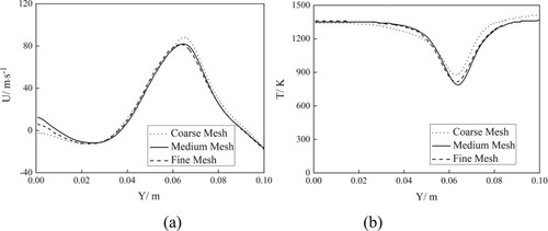
An unstructured mesh system with 3.4 million grids was employed in the premixer. The mean grid scale was 0.5 mm, which is sufficient for LES in previous research. The chamber adopted a hexahedral mesh with optimization in the area where reactions occur. To check the grid independence, we employed three different strategies with 0.5, 1.5, and 2.5 million cells. Figure illustrates the profiles of the mean axial velocity and temperature obtained by the three meshes. The coarse mesh yielded an obviously different result from the others, whereas the data from the medium mesh were similar to those from the fine mesh. Thus, the mesh with 1.5 million grids for original model was used in this study.
Figure 3. Profiles of (a) mean axial velocity and (b) temperature profiles predicted by different mesh schemes.
In the simulation of the combustor, the syngas and air inlet were specified according to Table , and the walls were regarded as the nonslip adiabatic boundary. In the simulation of the combustion chamber, the inflow data from the outlet of the premixer was adopted, and the walls were regarded as nonslip walls with constant temperature.
Running on an Intel cluster, an in-house source code package developed by our workgroup was applied to carry out the simulation. The code employs a semi-implicit Crank–Nicolson difference method with second-order accuracy as time–space coupled discrete method. For pressure term, velocity convection term and velocity viscous term, the code employs implicit difference methods with second-order accuracy. For scalar convection term, the code employs an implicit WENO difference method with third-order accuracy. Given the huge amount of computation involved in the LES of the chamber, a parallel strategy was adopted herein.
The simulation of each case was run until the flow time reached 2.0 s to obtain full development. Then, the statistical data were obtained in another 0.5 s. The time steps used in all cases were 2×10⁻⁶ s, and the max value of CFL is 0.6, guaranteed the computational stability and captured the dynamic processes of combustion. The simulations were completed on a massively parallel cluster, with one whole case costing about 2,400 CPU hours to obtain the final results.
2.4. Simulation cases
The original model of combustion chamber was simplified to further improve the calculation efficiency. The simplified model ignores two coaxial air inlets, which account for approximately 5% of the total air flow. As shown in Figure , given the low air velocity and no reaction occurs, their impact on the mainstream area can be neglected. Similar grid independence check has also been performed for the simplified model. Here, the mesh with 1.06 million grids for simplified model was used in this study.
Figure shows Sketch of the mesh for combustion chamber for original model and simplified model. Herein, D = 0.12 m, and the profiles of four axial locations are shown in Figure .Three simulation cases were set to investigate the effect of hydrogen addition on combustion characteristics. The details are listed in Table . By analyzing the results of the three cases, we can study the combustion characteristics and flame dynamics caused by the addition of hydrogen.
Figure 4. Sketch of the mesh for combustion chamber for original model (above) and simplified model (below).
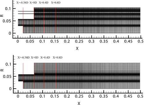
Table 2. Conditions of simulation cases.
3. Numerical methods
3.1. Subgrid model and governing equations
In this study, the combustion process was simulated using LES, which could capture most of the turbulent energy in large eddies. To describe the transportation of mass, momentum, species, and energy in three dimensions, we used the following Favre-filtered conservation equations:
(1)
(1)
(2)
(2)
(3)
(3)
(4)
(4)
In these equations, ‘∼’ and ‘-’ denote the Favre-filtered and Reynolds-filtered variables, respectively. The subgrid stress tensor in Equation (2), , is calculated using a dynamic Smagorinsky model shown in Equation (5), where the subgrid viscosity,
, and the subgrid kinetic energy,
, are calculated dynamically (Germano et al., Citation1991). Subgrid species and energy fluxes are approximated by the gradient model, as shown in Equations (6) and (7):
(5)
(5)
(6)
(6)
(7)
(7)
The chemical source species term, , and chemical source energy term,
, in Equations (3) and (4) could be obtained from reaction rate,
, which is calculated by the PaSR model (Berglund et al., Citation2010). This model has been proved to be accurate in the LES of swirling premixed combustion, and its expression is defined in the following section. The source term of the energy introduced by the radiation in Equation (4), is neglected.
3.2. PaSR model
In the LES of combustion, various models are proposed to solve the interaction between the turbulence and the chemical reaction. One intuitive approach is the finite chemistry model, in which the reaction rate is calculated using the well-known Arrhenius equation. Every variable in the Arrhenius equation can be decomposed into filtered and subgrid components after filtering.
The PaSR model is considered as an accurate finite rate model. It regards each computing grid as a small reactor, where fuel and oxygen are mixed and chemical reactions occur. As the thickness of the area where combustion occurs is smaller than the grid scale, only a part of the components in the grid participates in the chemical reaction. In the PaSR model, each LES cell can be divided into fine structures, where mixing and reactions are assumed to take place, and surroundings, dominated by large-scale coherent flow structures. The PaSR model expresses the influence of turbulence in the form of superimposed correction on the calculated value of the chemical reaction rate, instead of simply using the flow field parameters to calculate the chemical reaction rate. The model calculates the chemical reaction rate of each reaction step separately, and it can use multistep reaction mechanisms.
The PaSR model ignores scalar pulsation in fine structures, thus the effect of subgrid pulsations on chemical reaction rates was not considered in the model. Researchers have widely applied the PaSR model to the combustion field, and the most prediction of PaSR-LES is consistent with the experimental data (Berglund et al., Citation2010).
Global reaction rate in the PaSR model, , is defined as Equation (8).
(8)
(8)
In Equation (8), is calculated by the Arrhenius equation, and the chemical time scale,
, and turbulent time scale,
, are defined as follows:
(9)
(9)
(10)
(10)
3.3. Reaction mechanism
Extensive studies have explored premixed syngas combustion, especially in syngas combustion mechanisms. Marzouk and David Huckaby (Citation2010) compare the performance and computational cost of 8 syngas combustion mechanisms by using the PaSR model and a modified k-epsilon model. Carsten Olm et al. (Citation2015) tested 16 syngas combustion mechanisms against experimental data, and investigated the dependence of their predictions on the types of experiment and the experimental conditions.
Comparison of syngas combustion mechanisms are listed in Table . Syngas combustion mechanisms could be divided into detailed mechanisms and reduced mechanisms. Using detailed mechanisms can predict reactions more accurately, whereas using reduced mechanisms can reduce more computing resources and time. The time cost is at least a cubic function of the number of species, even a minor reduction in the number of species can result in substantial reduction in the computation time (Lu & Law, Citation2009).
Table 3. Comparison of syngas combustion mechanisms in recent years.
In the PaSR model, all species are solved. Hence, accurate reduced mechanisms should be adopted in the simulation to reduce the time cost. In the present study, Boivin mechanism and Sandia mechanism were adopted after measuring computing resources cost and prediction accuracy. The results were then compared with the experimental outcomes to verify their accuracy.
Boivin mechanism involves 4 reaction steps and 8 species (Boivin et al., Citation2011). A previous study showed that the mechanism can obtain reasonable flame speed and ignition time under various operating conditions. This mechanism is written as follows:
The Sandia mechanism is presented on the website of Sandia National Lab with 6 reaction steps and 10 species (Chen, Citation2002). Its accuracy was verified through a comparison with the results of a detailed mechanism. This mechanism is written as follows:
The same working condition as that presented in Table was set to verify the applicability of the two reaction mechanisms. The results are detailed in Section 4.1.
4. Results and discussion
4.1. Applicability of the two reaction mechanisms
To verify the applicability of the two reaction mechanisms, we conduct LES with the same working conditions as those in Table .
As the H radical is the most important intermediate product in the Boivin and Sandia mechanisms, the mass fraction of the H radical can reflect the reaction intensity in the chamber and is usually used to indicate flame structure. The isosurfaces of the H radical in the chamber obtained in both cases are shown in Figure . The Boivin mechanism could predict a similar flame structure to that predicted in the experiment (Figure ). The flame exhibits a double-layer structure and is stabilized near the wall. However, the flame structure predicted by the Sandia mechanism is blown off, which indicates a low reaction intensity. The simulation result from the Sandia mechanism is obviously different from the stable combustion state shown in the experiment.
Figure 5. Isosurfaces of H radical obtained by (a) Boivin mechanism and (b) Sandia mechanism.
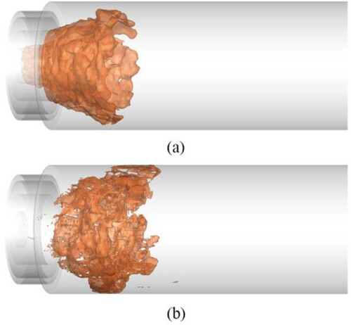
Figure shows the time-averaged temperatures obtained by the two mechanisms. The temperatures on the outlet predicted by both mechanisms are approximately 1,420 K, which is close to the experimental data (1,393 K). However, the Sandia mechanism obtains a longer and wider low-temperature region than the Boivin mechanism. This result coincides with the different prediction of flame structure in Figure . The mid-temperature, , defined as average value of outlet temperature and inlet temperature (the black thick line) denotes the flame length. As the temperature rises sharply near this value, the mixture combusts rapidly. The result obtained by the Boivin mechanism is about 88 mm, and that obtained by the Sandia mechanism is about 135 mm. Obviously, the Boivin mechanism can predict a more reasonable flame length compared with that in the experiment. Measured by a flue gas analyzer, the CO concentration at the outlet in the experiment is about 8 ppm (corrected to 15% oxygen by volume). The simulation adopting the Boivin mechanism predicts 11 ppm, whereas that based on the Sandia mechanism predicts 1.5 ppm. The former obtains better results than the latter.
Figure 6. Time-averaged temperatures obtained by (a) Boivin mechanism and (b) Sandia mechanism.
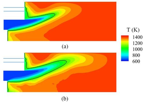
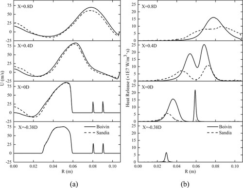
Figure shows radial profiles of mean axial velocity and mean heat release at four axial locations obtained by two mechanisms. As shown in Figure , for X= −0.38D, the mean axial velocity predicated by two mechanisms are exactly the same, since there is almost no reaction. For the other three cases, when R < 0.02 m, the axial velocity predicated by Boivin mechanism is lower compared with Sandia mechanism. When R > 0.02 m, the axial velocity predicated by Boivin mechanism is higher compared with Sandia mechanism, since heat release obtained by Boivin mechanism is higher.
Figure 7. Radial profiles of (a) mean axial velocity and (b) mean heat release at four axial locations obtained by two mechanisms.
The results imply that the Boivin mechanism can obtain more accurate simulation data compared with the experiment. Therefore, the following discussion is focused on the simulation results based on the Boivin mechanism, as well as the effect of hydrogen addition on the combustion characteristics in the chamber.
4.2. Flame structure
To investigate the effect of hydrogen addition ratio on combustion characteristics, we perform LES on three cases on the basis of the Boivin mechanism (Table ).
Evolution of instantaneous concentration of H radical for the three cases based on the Boivin mechanism are shown in Figure . The thick black line in the figure indicates the mid-temperature. In Figure , the concentration of the H radical is the highest near the isotherm of the mid-temperature; this result indicates that the flame burns violently near the black line. As the isotherm can indicate the flame structure, the isotherm can be approximated as the flame front to study the differences across the three cases.
Figure 8. Evolution of instantaneous concentration of H radical for (a) Syngas25, (b) Syngas45, (c) Syngas100.
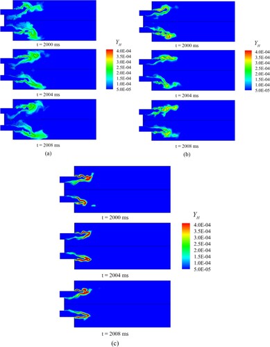
Syngas25 has the lowest hydrogen content, but its flame length is the longest, and its flame front extends radially. In addition, the high concentration of H radical downstream of the flame front covers a large area, and thus, the reaction rate is low. When the H2 content increases from 20% to 45%, the flame shortens radially, and the flame front shrinks toward upstream. For Syngas100, the flame front continues to shrink toward upstream, and H radical are highly concentrated near the flame front. The area of high-concentration H radical downstream of the flame front decreases because the Le of hydrogen is lower than that of carbon monoxide and regions with high H radical concentrations caused by preferential diffusion appear.
Karlovitz number (Ka) also affects the distribution of H radical. Ka is defined as the ratio of the chemical reaction time scale to the turbulent Kolmogorov time scale. As the hydrogen combustion requires little time, the chemical reaction time scale becomes small, thus Ka decreases with hydrogen addition ratio increasing. With hydrogen decreasing, i.e. Ka increasing, the turbulent vortex structure could easily penetrate the flame surface and affect the internal flame structure, which will promote or suppress chemical reactions. According to the previous research performed by Wang et al. (Citation2018), with increasing Ka, i.e. increasing turbulence intensity, the reactions will be promoted at weak reaction regions and suppressed at intense reaction regions, leading to the increase of H radical at weak reaction regions. As we can see form Figure , with hydrogen content increasing, affected by decreasing Ka and Le, H radical distributed narrowly, which indicates reaction zone is thinned.
With the increase in hydrogen addition ratio, the flame surface transforms smooth from wrinkly. The observation is consistent with the previous research performed by Wang and Abraham (Citation2018); they concluded that with Ka increasing, the probability of forming highly curved flame surface becomes higher. The influence of the turbulent vortex structure on the flame surface decreases with hydrogen content increasing, eventually leading to the flame surface becoming smooth. The other characteristics of the flow field in the chamber will be detailed in the next section.
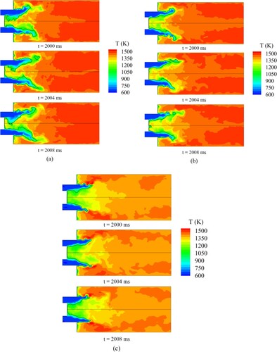
Figure shows evolution of instantaneous temperatures for the three cases. For Syngas25, a high-temperature zone appears near the outlet of the combustion chamber, and the maximum mean temperature is 1,490 K. For Syngas45, the high-temperature zone moves upstream, and the maximum mean temperature rises to 1,510 K. For Syngas100, a high-temperature zone appears downstream of the flame front, and the maximum mean temperature is 1,570 K. The change in the location of the high-temperature zone is consistent with the prediction of flame structure in Figure . The observation is consistent with the main conclusion of Park et al. (Citation2009). As the hydrogen fraction increases, the Le of the fuel decreases, leading to the appearance of a high-temperature zone caused by preferential diffusion. The result is similar to the previous research performed by Fu et al. (Citation2014), they observed that preferential diffusion leads to the formation of a high temperature zone in the flow field.
Figure 9. Evolution of instantaneous temperature for (a) Syngas25, (b) Syngas45, (c) Syngas100.
4.3. Flow field and flashback
Figure (a) shows the radial profiles of the mean axial velocity at four axial locations across different cases. As shown in Figure (a), CTRZ appears in the downstream of the flame front near the centerline since the axial velocity in the region is negative. The CTRZ provides a dominant flame stabilization mechanism. Shear layer and turbulence affect the flow in CTRZ (Huang & Yang, Citation2009). Meanwhile, corner recirculation zone (CRZ) appears at the expansion corner of the chamber.
Figure 10. Radial profiles of mean and fluctuating axial velocity at four axial locations.
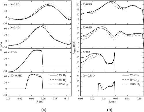
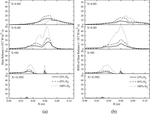
Although the hydrogen fraction in syngas varies greatly, the average axial velocity at each location presents the same trend. Compared with those in Syngas25 and Syngas45, the peaks of the mean velocity in Syngas100 occur at a larger radial location. The maximum velocity in Syngas100 is higher than that in the other cases due to the high combustion heat release shown in Figure (a). Figure (a) shows the radial profiles of the mean heat release rates at four locations for different cases.
Figure 11. Radial profiles of mean and fluctuating heat release rates at four axial locations.
In the combustion chamber, the change of axial velocity is affected by the two factors below: swirling motion and combustion heat release. The swirling motion diverges the flow and reduces axial velocity, whereas combustion heat release expands the gas volume and increases the axial flow velocity.
Figure (b) shows the radial profiles of the fluctuating axial velocity at four axial locations across different cases. The simulation results accurately capture the position of the inner and outer shear layers, which are two peaks of velocity pulsations in the radial direction. When X = 0.4D, 0.03 m < R < 0.04 m is the inner shear layer, and 0.06 m < R < 0.07 m is the outer shear layer. Large-scale coherent flow structures are generated in the shear layer regions and shed downstream sequentially due to Kelvin-Helmholtz instabilities (Huang & Yang, Citation2009). These vortex structures significantly influence the combustion process.
The combustion reaction can cause velocity pulsations and provide energy for the existence of the shear layer. As hydrogen has a high thermal conductivity, its reaction position is concentrated upstream of the flow field, and the flame length is short. Therefore, the effect of combustion on the shear layer downstream of the flow field is minimal. Relative to those of Syngas25 and Syngas45, the peak of the fluctuating velocity in Syngas100 is decreased.
The radial profiles of the fluctuating heat release rates at four locations for different cases are shown in Figure (b). With the increase in added hydrogen, the value change of the RMS heat release becomes sharp, and the range of the RMS heat release becomes narrow; hence, the flame surface becomes smooth. The result is consistent with the discussion on Figure .
Figure shows the distribution of the mean axial velocity and streamline for every case. Several salient structures are observed in the flow field: vortex breakdown-induced CTRZ, PVC surrounding the CTRZ, shear layers (including inner shear layers and outer shear layers), and CRZ. Vortex breakdown usually manifests as an abrupt change in the core of a slender vortex. It provides the dominant flame stabilization mechanism in this region, which exists internal stagnation points and reversed flows.
Figure 12. Distribution of mean axial velocity and streamline for (a) Syngas25, (b) Syngas45, (c) Syngas100.
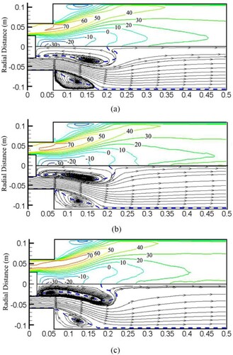
As we can see from Figure , flame kernel detaches from the shear layers intermittently, and the detached flame kernel becomes small with hydrogen content increasing. After detaching from flame, the flame kernel reaches the CRZ, and flame ignites intermittently, which could make the flame extend radially. Since Syngas25 has the larger flame kernel, the flame could extend radially, whereas Syngas100 hardly extends radially. Hence, CRZ shrinks and recirculation weakens with hydrogen content increasing as shown in Figure . The sudden and intermittent ignition in the CRZ leads to large fluctuations in heat release and temperature (as shown in Figure ), which is to be considered as a potential mechanism leading to thermo-acoustic instability (Soufien Taamallah et al., Citation2016).
As hydrogen has a high thermal conductivity, a high hydrogen addition ratio leads to a low heat release rate downstream and a high heat release rate upstream. As the hydrogen addition ratio increases from 25 to 100, the size of the CTRZ decreases, the stagnation point of the vortex breakdown moves upstream and eventually approaches the center body, then flashback caused by CIVB occurs. Similar observations in CH4-H2 syngas have also been reported by De and Acharya (Citation2012a), they found high hydrogen content in CH4-H2 syngas makes the CTRZ compact, leading to flashback.
CIVB is promoted by the high gravimetric heating value of hydrogen. As the flame moves upstream as the hydrogen fraction increases, it will encounter a fuel-rich zone, thereby resulting in hydrogen with a high flame propagation velocity. The basic mechanism of CIVB is that the flame contributes to vortex breakdown, leading to CTRZ and the stagnation point. As the flame moves upstream, the location of vortex breakdown advances further upstream. This process will continue as the flame moves further upstream.
The PVC is an unsteady flow structure that central vortex core precesses around the symmetry axis at a well-defined frequency. This phenomenon has often been reported in turbulent swirl burners (Froud et al., Citation1995; N Syred et al., Citation1997). The PVC is usually linked to vortex breakdown and the associated recirculation zone in a high Re flow.
Figure shows evolution of instantaneous pressure over one cycle for three cases. The thick black line indicates the contour of zero axial velocity, and environmental pressure, pe = 101,325 Pa. Here, time cycle of swirling, , the tangential average velocity,
65 m/s.
Figure 13. Evolution of instantaneous pressure over one cycle for (a) Syngas25, (b) Syngas45, (c) Syngas100.
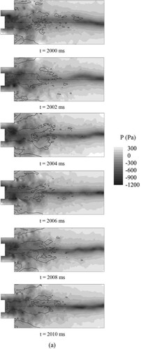

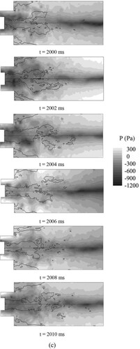
For Syngas25, we can clearly observe the existence of the PVC (low pressure core), the PVC is situated near the zero velocity line. This phenomenon is consistent with the observation reported by Syred and Beer (Nicholas Syred, Citation2006) that the PVC is usually situated on the boundary of the reverse flow zone between the zero velocity and the zero streamline. As we can see from Figure , the PVC occurs near the center body and precesses downstream.
For Syngas45, we can also observe the existence of the PVC (low pressure core), though the pressure of the PVC becomes higher relative to Syngas25. Since higher heat released by hydrogen makes pressure becomes higher. Similar to Syngas 25, the PVC starts occurs near the center body and precess downstream.
For Syngas100, we can observe the PVC form t = 2100 ms to t = 2106 ms, and the pressure of the PVC is higher relative to Syngas25. However, the PVC disappears form t = 2108 ms to t = 2110 ms, which means the PVC cannot exist stably in a time cycle.
As shown in Figure , when the hydrogen addition ratio increases, the flame temperature rises greatly. As the temperature rises, the viscosity of the gas improves greatly, and the turbulence, in particular, the turbulent stress increases significantly. These factors generally explain why the PVC cannot exist stably in the combustion (Huang & Yang, Citation2009).
5. Conclusions
In this work, the effects of hydrogen addition ratio for CO-H2 syngas on combustion characteristics are numerically investigated in a swirl burner via LES. The main conclusions can be drawn as follows:
Compared with experimental data, the Boivin mechanism predicts a more reasonable flame structure.
As the H2 addition increases, the flame temperature rises, and the flame length decreases due to preferential diffusion. Besides, H radical distributed narrowly, and the flame surface becomes smooth.
As hydrogen has a high thermal conductivity, the reaction location moves upstream as the hydrogen content increases. This condition leads to a high heat release and RMS of heat release. Meanwhile, the effect of combustion on the shear layer downstream decreases.
As the H2 addition increases, the size of the CTRZ decreases, and flashback caused by CIVB occurs.
The PVC cannot exist stably in Syngas100, though it can be clearly observed in other cases. And the pressure of the PVC is higher in Syngas100 and Syngas45 relative to Syngas25.
Due to the limitation of computing resource, we just set three cases to investigate the effect of hydrogen addition ratio on combustion characteristics. In the future, more cases with various compositions should be set for further research.
Disclosure statement
No potential conflict of interest was reported by the author(s).
Additional information
Funding
References
- Abadi, A. M. E., Sadi, M., Farzaneh-Gord, M., Ahmadi, M. H., & Chau, K. W. (2020). A numerical and experimental study on the energy efficiency of a regenerative heat and mass exchanger utilizing the counter-flow maisotsenko cycle. Engineering Applications of Computational Fluid Mechanics, 14(1), 1–12. https://doi.org/https://doi.org/10.1080/19942060.2019.1617193
- Bazooyar, B., & Darabkhani, H. G. (2019). Analysis of flame stabilization to a thermo-photovoltaic micro-combustor step in turbulent premixed hydrogen flame. Fuel, 257, 115989. https://doi.org/https://doi.org/10.1016/J.FUEL.2019.115989
- Berglund, M., Fedina, E., Fureby, C., Tegnér, J., & Sabel’nikov, V. (2010). Finite rate chemistry large-eddy simulation of self-ignition in a supersonic combustion ramjet. AIAA Journal, 48(3), 540–550. https://doi.org/https://doi.org/10.2514/1.43746
- Boivin, P., Jiménez, C., Sánchez, A. L., & Williams, F. A. (2011). A four-step reduced mechanism for syngas combustion. Combustion and Flame, 158(6), 1059–1063. https://doi.org/https://doi.org/10.1016/J.COMBUSTFLAME.2010.10.023
- Carsten Olm, I. G. Z., Varga, T., Curran, H. J., & Turányi, T. (2015). Comparison of the performance of several recent syngas combustion mechanisms. Combustion and Flame, 162(5), 1793–1812. https://doi.org/https://doi.org/10.1016/j.combustflame.2014.12.001
- Chen, J.-Y. (2002). International Workshop on Measurement and Computation of Turbulent Flames - CO/H2/N2 6-step reduced mechanism. https://tnfworkshop.org/chemistry/.
- Dam, B., Corona, G., Hayder, M., & Choudhuri, A. (2011). Effects of syngas composition on combustion induced vortex breakdown (CIVB) flashback in a swirl stabilized combustor. Fuel, 90(11), 3274–3284. https://doi.org/https://doi.org/10.1016/J.FUEL.2011.06.024
- Daniele, S., Jansohn, P., & Boulouchos, K. (2009). Experimental investigation of lean premixed syngas combustion at gas turbine relevant conditions: Lean blow out limits, emissions and turbulent flame speed. Paper presented at the Proceedings of 32nd annual meeting of the Italian section on the combustion colloquia. April 26-28.
- Daniele, S., Jansohn, P., Mantzaras, J., & Boulouchos, K. (2011). Turbulent flame speed for syngas at gas turbine relevant conditions. Proceedings of the Combustion Institute, 33(2), 2937–2944. https://doi.org/https://doi.org/10.1016/J.PROCI.2010.05.057
- Davis, S. G., Joshi, A. V., Wang, H., & Egolfopoulos, F. (2005). An optimized kinetic model of H2/CO combustion. Proceedings of the Combustion Institute, 30(1), 1283–1292. https://doi.org/https://doi.org/10.1016/J.PROCI.2004.08.252
- De, A., & Acharya, S. (2012a). Dynamics of upstream flame propagation in a hydrogen-enriched premixed flame. International Journal of Hydrogen Energy, 37(22), 17294–17309. https://doi.org/https://doi.org/10.1016/J.IJHYDENE.2012.08.019
- De, A., & Acharya, S. (2012b). Parametric study of upstream flame propagation in hydrogen-enriched premixed combustion: Effects of swirl, geometry and premixedness. International Journal of Hydrogen Energy, 37(19), 14649–14668. https://doi.org/https://doi.org/10.1016/J.IJHYDENE.2012.07.008
- Eivaz, A., Bahman, N., Mohsen, J., Sina, F. A., Shahaboddin, S., & Kwok-Wing, C. (2018). Experimental and computational fluid dynamics-based numerical simulation of using natural gas in a dual-fueled diesel engine. Engineering Applications of Computational Fluid Mechanics, 12(1), 517–534. https://doi.org/https://doi.org/10.1080/19942060.2018.1472670
- E. O., Oluyede, & J. N. , Phillips. (2007). Fundamental impact of firing syngas in gas turbines. Paper presented at the ASME Turbo Expo 2007: Power for Land, Sea, and Air. May 14–17.
- Faizollahzadeh Ardabili, S., Najafi, B., Shamshirband, S., Minaei Bidgoli, B., Deo, R. C., & Chau, K. W. (2018). Computational intelligence approach formodeling hydrogen production: A review. Engineering Applications of Computational Fluid Mechanics, 12(1), 438–458. https://doi.org/https://doi.org/10.1080/19942060.2018.1452296
- Froud, D., O'doherty, T., & Syred, N. (1995). Phase averaging of the precessing vortex core in a swirl burner under piloted and premixed combustion conditions. Combustion and Flame, 100(3), 407–410. https://doi.org/https://doi.org/10.1016/0010-2180(94)00167-Q
- Fu, J., Tang, C., Jin, W., & Huang, Z. (2014). Effect of preferential diffusion and flame stretch on flame structure and laminar burning velocity of syngas bunsen flame using OH-PLIF. International Journal of Hydrogen Energy, 39(23), 12187–12193. https://doi.org/https://doi.org/10.1016/J.IJHYDENE.2014.06.043
- Germano, M., Piomelli, U., Moin, P., & Cabot, W. H. (1991). A dynamic subgrid-scale eddy viscosity model. Physics of Fluids A: Fluid Dynamics, 3(7), 1760–1765. https://doi.org/https://doi.org/10.1063/1.857955
- Huang, Y., & Yang, V. (2009). Dynamics and stability of lean-premixed swirl-stabilized combustion. Progress in Energy and Combustion Science, 35(4), 293–364. https://doi.org/https://doi.org/10.1016/J.PECS.2009.01.002
- Issakhov, A., Alimbek, A., & Issakhov, A. (2020). A numerical study for the assessment of air pollutant dispersion with chemical reactions from a thermal power plant. Engineering Applications of Computational Fluid Mechanics, 14(1), 1035–1061. https://doi.org/https://doi.org/10.1080/19942060.2020.1800515
- Jafari-Sejahrood, A., Najafi, B., Ardabili, S. F., Shamshirband, S., & Chau, K. W. (2019). Limiting factors for biogas production from cow manure: Energo-environmental approach. Engineering Applications of Computational Fluid Mechanics, 13(1), 954–966. https://doi.org/https://doi.org/10.1080/19942060.2019.1654411
- Kathrotia, T., Fikri, M., Bozkurt, M., Hartmann, M., Riedel, U., & Schulz, C. (2010). Study of the H+ O+ M reaction forming OH∗: Kinetics of OH∗ chemiluminescence in hydrogen combustion systems. Combustion and Flame, 157(7), 1261–1273. https://doi.org/https://doi.org/10.1016/J.COMBUSTFLAME.2010.04.003
- Keromne, A., Metcalfe, W. K., Heufer, K. A., Donohoe, N., Das, A. K., Sung, C. J., … Mathieu, O. (2013). An experimental and detailed chemical kinetic modeling study of hydrogen and syngas mixture oxidation at elevated pressures. Combustion and Flame, 160(6), 995–1011. https://doi.org/https://doi.org/10.1016/J.COMBUSTFLAME.2013.01.001
- Li, J., Zhao, Z., Kazakov, A., Chaos, M., & ScireJrJ. J. (2007). A comprehensive kinetic mechanism for CO, CH2O, and CH3OH combustion. International Journal of Chemical Kinetics, 39(3), 109–136. https://doi.org/https://doi.org/10.1002/KIN.20218
- Lu, T., & Law, C. K. (2009). Toward accommodating realistic fuel chemistry in large-scale computations. Progress in Energy and Combustion Science, 35(2), 192–215. https://doi.org/https://doi.org/10.1016/J.PECS.2008.10.002
- Marzouk, O. A., & David Huckaby, E. (2010). A comparative study of eight finite-rate chemistry Kinetics for Co/H2 combustion. Engineering Applications of Computational Fluid Mechanics, 4(3), 331–356. https://doi.org/https://doi.org/10.1080/19942060.2010.11015322
- Park, J., Lee, D. H., Yoon, S. H., Vu, T. M., Yun, J. H., & Keel, S. I. (2009). Effects of Lewis number and preferential diffusion on flame characteristics in 80%H2/20%CO syngas counterflow diffusion flames diluted with He and Ar. International Journal of Hydrogen Energy, 34(3), 1578–1584. https://doi.org/https://doi.org/10.1016/j.ijhydene.2008.11.087
- Sun, X., Li, W., Huang, Q., Zhang, J., & Sun, C. (2020). Large eddy simulations of wind loads on an external floating-roof tank. Engineering Applications of Computational Fluid Mechanics, 14(1), 422–435. https://doi.org/https://doi.org/10.1080/19942060.2020.1718757
- Sun, H., Yang, S., Jomaas, G., & Law, C. K. (2007). High-pressure laminar flame speeds and kinetic modeling of carbon monoxide/hydrogen combustion. Proceedings of the Combustion Institute, 31(1), 439–446. https://doi.org/https://doi.org/10.1016/J.PROCI.2006.07.193
- Syred, N. (2006). A review of oscillation mechanisms and the role of the precessing vortex core (PVC) in swirl combustion systems. Progress in Energy and Combustion Science, 32(2), 93–161. https://doi.org/https://doi.org/10.1016/J.PECS.2005.10.002
- Syred, N., Fick, W., O'doherty, T., & Griffiths, A. (1997). The effect of the precessing vortex core on combustion in a swirl burner. Combustion Science and Technology, 125(1-6), 139–157. https://doi.org/https://doi.org/10.1080/00102209708935657
- Taamallah, S., Shanbhogue, S. J., & Ghoniem, A. F. (2016). Turbulent flame stabilization modes in premixed swirl combustion: Physical mechanism and Karlovitz number-based criterion. Combustion and Flame, 166, 19–33. https://doi.org/https://doi.org/10.1016/J.COMBUSTFLAME.2015.12.007
- Taamallah, S., Vogiatzaki, K., Alzahrani, F. M., Mokheimer, E. M. A., Habib, M. A., & Ghoniem, A. F. (2015). Fuel flexibility, stability and emissions in premixed hydrogen-rich gas turbine combustion: Technology, fundamentals, and numerical simulations. Applied Energy, 154, 1020–1047. https://doi.org/https://doi.org/10.1016/j.apenergy.2015.04.044
- Tangermann, E., & Pfitzner, M. (2008). Numerical investigation of flame flashback into swirling flow. Paper presented at the ASME Turbo Expo 2008: Power for Land, Sea, and Air. June 9–13.
- Tangermann, E., Pfitzner, M., Konle, M., & Sattelmayer, T. (2010). Large-eddy simulation and experimental observation of combustion-induced vortex breakdown. Combustion Science and Technology, 182(4-6), 505–516. https://doi.org/https://doi.org/10.1080/00102200903463126
- Wang, Z., & Abraham, J. (2018). Effects of Karlovitz number on flame surface wrinkling in turbulent lean premixed methane-Air flames. Combustion Science and Technology, 190(3), 363–392. https://doi.org/https://doi.org/10.1080/00102202.2017.1391232
- Wang, X., Jin, T., Xie, Y., & Luo, K. H. (2018). Effects of pressure and Karlovitz number on the turbulence-flame interactions in lean premixed H2/air flames. Fuel, 234, 1293–1300. https://doi.org/https://doi.org/10.1016/J.FUEL.2018.07.158
- Wang, Q., McDonell, V., Steinthorsson, E., Mansour, A., & Hollon, B. (2009). Correlating flashback tendencies for premixed injection of hydrogen and methane mixtures at elevated temperature and pressure. Paper presented at the ASME Turbo Expo 2009: Power for Land, Sea, and Air. June 8–12.
- Wang, Y., Yu, Z., Kong, W., Wang, B., & Ai, Y. (2016). American Patent No. US9234662B2.
- Watanabe, H., & Otaka, M. (2006). Numerical simulation of coal gasification in entrained flow coal gasifier. Fuel, 85(12-13), 1935–1943. https://doi.org/https://doi.org/10.1016/J.FUEL.2006.02.002
- Yu, Z., Wu, X., Wu, F., Wang, Y., Kong, W., Feng, Y., & Wang, H. (2013). Numerical analysis of the conceptual design of arrayed-vanes premixer for gas turbine combustors burning high-hydrogen fuels. Paper presented at the ASME Turbo Expo 2013: Turbine technical conference and Exposition. June 3–7.
- Zheng, Y., Zhu, M., Martinez, D. M., & Jiang, X. (2013). Large-eddy simulation of mixing and combustion in a premixed swirling combustor with synthesis gases. Computers & Fluids, 88, 702–714. https://doi.org/https://doi.org/10.1016/J.COMPFLUID.2013.04.003