
 ?Mathematical formulae have been encoded as MathML and are displayed in this HTML version using MathJax in order to improve their display. Uncheck the box to turn MathJax off. This feature requires Javascript. Click on a formula to zoom.
Abstract
Turbine guide vane faces extremely high thermal load, especially on the leading edge region. In order to enhance cooling performance, the present study investigates the effects of leading-edge film cooling arrangements by adiabatic and aero-thermal coupled simulation. The three-row cooling design of the 25° inclined angle with the trenched holes is used to replace five-row showerhead holes. The model is employed after conducting the numerical validation. The results show that at coolant mass flow of 0.00171 kg/s, three-row showerhead film cooling with trenched holes can provide higher laterally averaged adiabatic cooling effectiveness than three-row round holes. It can also improve cooling performance in most of the leading-edge regions, compared with five-row showerhead cooling arrangements. The three-row cooling design with trenched holes can still obtain the highest area-averaged effectiveness on either the suction side or the pressure side of the leading edge. Besides, the trenched holes are also beneficial to the reduction of the aerodynamic losses. In the aero-thermal coupled simulation, the improvement of the three-row cooling design with trenched holes decreases because of the internal cooling effect. It is also proved that the transverse trench would not lead to a local high temperature region on the metal surface. The trenched configuration above can be used on the first-stage turbine vane to increase turbine inlet temperature, improve engine efficiency, and prolong engine life.
Nomenclature
| Bi | = | Biot number |
| Cp | = | Total pressure loss coefficient |
| D | = | Film cooling hole diameter [m] |
| H | = | Heat transfer coefficient [W/(m2·K)] |
| M | = | Blowing ratio of coolant to mainstream, |
| P | = | Pressure [Pa] |
| qm | = | Mass flow [kg/s] |
| Q | = | Heat flux [W/m2] |
| S | = | Streamwise distance [m] |
| T | = | Temperature [K] |
| X Y Z | = | Cartesian coordinates |
Subscript
| ∞ | = | Mainstream |
| Ave | = | Averaged |
| Aw | = | Adiabatic |
| j | = | Coolant jet |
Greek symbols
| α | = | Injection angle [°] |
| η | = | Adiabatic effectiveness, |
| ηL | = | Laterally averaged cooling effectiveness |
| ηS | = | Area averaged cooling effectiveness |
| θ | = | Non-dimensional temperature |
| μ | = | Viscosity [Pa·s] |
| ρ | = | Density [kg/m3] |
| τ | = | Non-dimensional temperature on the thermal barrier coating |
| φ | = | Non-dimensional temperature on the metal surface |
Abbreviation
| Exp | = | Experimental result |
| LE | = | Leading edge |
| PS | = | Pressure side |
| SS | = | Suction side |
| TBC | = | Thermal barrier coating |
1. Introduction
Gas turbine plays a critical role in the jet engine, ship propulsion, land-based power stations, and other industrial fields. With the higher demand for power output and efficiency, the cooling requirements in the hot components are increasing, and high-performance film cooling technologies are urgently needed. The cooling requirements in the hot components are increasing with a higher demand for power output and efficiency. Film cooling is a critical technology for the hot components in gas turbine. Meanwhile, the leading edge (LE) region confronts the highest heat load (York & Leylek, Citation2002). Therefore, a reliable arrangement of high-performance film cooling holes is more and more worthy of the attention.
To obtain better coolant protection for the turbine LE, several rows of showerhead holes are arranged on the LE region. The flow characteristics of leading edge film cooling are different from those in other turbine locations. The mainstream is strongly curved near the leading edge region. The coolant, which is just ejected from holes, turns to bend towards the vane leading edge under the effect of mainstream flow. Then, the coolant flow characteristics are affected by various factors with developing along the streamwise direction. These factors include the interaction of the coolant between multiple rows of cooling holes, the change of local curvature and pressure gradient, etc. Polanka et al. (Citation1999) and Witteveld et al. (Citation1999) studied the LE cooling performance of round holes under different blowing ratios and turbulence intensity. They found that, unlike flat film cooling, the laterally averaged cooling effectiveness (ηL) can be improved by increasing the blowing ratio under the LE flow conditions. Similarly, Nathan et al. (Citation2014) experimentally found that as the momentum ratio increased, the downstream cooling effectiveness (η) also gradually increased, especially at the momentum ratios from 2.9 to 4.7. Li et al. (Citation2019) studied the LE film cooling on the twist blade at different blowing ratios and rotating speeds. High rotating speed leaded to the change of stagnation line and the increased averaged blowing ratio improved the η.
Zhang and Pudupatty (Citation2000) experimentally studied the effects of 45°, 90°, and 135° compound angles on cooling performance at different blowing ratios. The highest η was obtained while compound angle is 45°. Gao et al. (Citation2017) concluded that the compound angle could reduce the LE cooling performance when the trailing edge of the hole entrance faces against the mainstream direction. Other research focuses on the influence of coolant from endwall (Du et al., Citation2017) and internal impingement cooling (Liu, Zhu et al., Citation2014; Taslim & Khanicheh, Citation2006) on the LE cooling performance. An et al. (Citation2005) concluded that to obtain effective film coverage on both sides of the stagnation line, the following needs to be met. First, film cooling holes must be arranged on the actual stagnation line. The second is that the cooling holes must have a certain radial inclined angle.
The high-performance LE cooling structure can improve the turbine life and reliability. Mouzon et al. (Citation2005) tried to further reduce the LE thermal load by expanded holes. Elnady et al. (Citation2013) showed that the smooth expansion hole has a higher η than the traditional round cooling hole. Kim and Kim (Citation2004) concluded that the laidback holes have higher spanwise coolant coverage by comparison to tear-drop holes. Then, the η distributions of different hole pitches and inclined angles are further investigated for the laidback holes by Liu, Ye et al. (Citation2014). Ye et al. (Citation2020) investigated the heat transfer characteristics of counter-inclined cylindrical and laidback holes. Gao and Han (Citation2009) and Li et al. (Citation2014) discussed the effect of the compound angle for the laidback holes at different density ratios.
Since Bunker (Citation2002) proposed the trenched film hole, researchers have carried out a series of research on the influence of geometric parameters and flow conditions. Lu et al. (Citation2005) experimentally showed that the trenched hole can ensure that the coolant was spread in the spanwise direction before being mixed with the high temperature mainstream. Khalatov et al. (Citation2017) and Zhang et al. (Citation2020) also proved the higher cooling performance of the trenched hole. Meanwhile, the heat transfer coefficient downstream of trenched holes did not increase significantly, compared with traditional round holes. Lu et al. (Citation2009) and Lee and Kim (Citation2014) investigated the cooling characteristics of different trench parameters. Lu et al. (Citation2009) found that at the density ratio of DR = 1.08, 0.75D trench depth had higher η than 0.5D and 1D depths. The 2D and 3D trench widths obtained a similar cooling performance. Besides, a higher ηL can be obtained within a certain blowing ratio range, by comparison with the fan-shaped and cratered holes (Dorrington et al., Citation2007; Waye & Bogard, Citation2007). The advantages of trenched holes were also studied on the turbine vane (Albert & Bogard, Citation2013; Barigozzi et al., Citation2012; Harrison et al., Citation2009; Islami et al., Citation2007; Ravi & Parammasivam, Citation2019).
It has been proved that more rows of showerhead holes can provide a significantly higher cooling performance (Gao & Han, Citation2009). Meanwhile, the previous study Hou, Wen, Tang, et al. (Citation2019) also shows that the LE trenched holes can improve cooling performance in the range of common blowing ratios. Therefore, it can imagine that five rows of showerhead holes could be replaced by three rows with trenched holes. Besides, the previous studies were mainly conducted with the simplified model, and lacked the discussion in real turbine environments. The objective of this study is to numerically investigate four different leading-edge film cooling configurations with and without trenched holes applied on C3X turbine blade under real turbine flow conditions, and to find if the configuration of three rows with trenched holes can be used to obtain better cooling performance than five rows of showerhead holes at a lower manufacturing cost. Besides, aero-thermal coupled simulation is conducted to further analyze the cooling effect under real turbine heat transfer conditions.
2. Numerical method
2.1. Computational model
2.1.1. Fluid domain
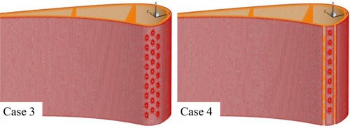
NASA C3X turbine blade (Hylton et al., Citation1983) is used in the present study. Table presents the geometric parameters of the C3X vane, and the physical model is shown in Figure . Based on this turbine blade, Turner et al. Turner et al. (Citation1985) conducted experimental research on turbine guide vane models with showerhead cooling holes. In this study, the baseline case that with five rows of showerhead holes is named Case 1. It needs to be defined in advance. The suction (SS) and pressure (PS) side are bounded by the geometric stagnation line. In the following discussion, the PS side is defined as the negative direction, and the SS area is defined as the positive direction. Figure (a) shows the definition of inclined angle and trench parameters, and Figure (b,c) show the different film cooling configurations. The middle row is located on the geometric stagnation line for the five-row showerhead cooling design. The hole number of the middle row is ten, as shown in Figure (b). Case 1 and Case 2 are based on five-row showerhead holes’ study of Turner et al. (Citation1985). The cooling holes in Case 1 are all round and their diameter is D = 0.99 mm. The inclined and compound angle is 45° and 90°, respectively. The hole spacing between two adjacent rows is 4D and the lateral hole spacing is 7.5D in each row. Five rows of showerhead holes are also used in Case 2. The difference is that trenched holes are arranged on the LE PS and SS side. According to the previous study Hou, Wen, Tang, et al. (Citation2019), the round holes arranged near the actual stagnation line can provide the similar cooling performance, compared with the trenched holes. However, trenched holes can improve the coolant coverage when arranging away from the stagnation line. For the present study, in Case 1 and Case 2, the cooling holes of the first row on the PS side and the geometric stagnation line are all located on either side of the actual stagnation line. As these two rows of holes are located near the actual stagnation line, according to the above conclusion, the round holes are arranged at these two positions. Then, the trenched holes are arranged downstream of these two positions, respectively. Therefore, as shown in Figure (b), the trenched holes were arranged on the second cooling row on the PS side and the first row on SS side in Case 2. The trench width and depth is 2D and 0.5D, respectively.
Figure 1. NASA C3X vane model with LE film cooling.
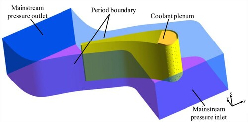
Figure 2. Geometric model.

Table 1. C3X vane parameters.
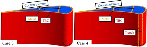
Case 3 and Case 4 use a three-row showerhead hole structure, as shown in Figure (b). The film cooling arrangements of Case 3 and Case 4 refer to three-row showerhead holes’ study of simplified model by Hou et al. (Citation2019). It has been proved that three-row configuration with trenched holes can significantly enhance film coverage and achieve full-coverage film cooling. It needs to mention that the design purpose of five-row showerhead cooling design is to achieve higher cooling performance by the superimposed effects of staggered cooling holes on the SS and PS sides. Since three-row configuration can achieve full-coverage film coverage, the authors considers that it is not necessary to arrange another row on the SS and PS side respectively. The configuration parameters of Case 3 and Case 4 are as follows. The middle row is arranged near the actual stagnation line. The hole diameter, the incidence angle, the row pitch, and the hole spacing of Case 3 and Case 4 are the same as Case 1 and Case 2. The difference is that the inclined angle of the holes is 25°. The original showerhead cooling design adopts five rows of staggered holes with a 45° inclined angle (Turner et al., Citation1985). However, the inclined hole angle is usually controlled between 20° and 35°, considering the coolant attachment and manufacturing limitations. In Case 4, the trench width and depth are 2D and 0.5D respectively. In addition, in order to perform aero-thermal coupling calculation, the coolant plenum near the LE has been redesigned.
2.1.2. Aero-thermal coupled model
In order to further study the relationship between adiabatic results and actual cooling performance, the present study also conducts aero–thermal coupled simulation. Three coolant plenums are designed for the C3X blade. The coolant of showerhead holes is provided by the plenum near the LE, As shown in Figure , only Case 3 and Case 4 are employed to make the comparison for better control of the influence of different parameters.
Figure 3. The vane model for the aero-thermal coupled calculation.
2.2. Boundary conditions
The ideal compressible gas is used in the numerical simulation (Dong, Citation2009). The relationship between viscosity and temperature using Sutherland formula is as follows:
(1)
(1) Where μ0 = 1.716 × 10⁻⁵ Pa·s, T0 = 273.11 K, S = 110.56 K.
The specific heat capacity of mainstream gas is fitted by polynomial (Dong, Citation2009), and the relationship is as follows:
(2)
(2) Where a0 = 957.110256, a1 = 0.2365234, a2 = 5.141114 × 10⁻⁶, a3 = −3.3917446 × 10⁻⁹, a5 = −6.0929646 × 10⁻¹².
In this paper, the 4313 operating condition in the experiment (Turner et al., Citation1985) is used for numerical validation and research. The turbine outlet Reynolds number is 1.5 × 10⁶, and the outlet Mach number is 0.9. Both inlet and outlet of mainstream adopt pressure boundary. The two sides of the mainstream fluid domain use periodic conditions. The boundary conditions in this study based on the 4313 condition are concluded in Table . The mass flow boundary condition is employed for the coolant inlet. Different inlet coolant mass flow will cause the difference in the averaged blowing ratio in the design of the five-row and three-row showerhead holes. The blowing ratio M is defined as , where
and
are coolant jet and mainstream parameters respectively. In details,
is calculated by the jet massflow average parameters on the outlet of film cooling holes.
is calculated by the mainstream inflow parameters in front of the LE region. The local blowing ratios of different configurations and flow conditions are shown in Table .
Table 2. 4313 boundary conditions for the C3X vane.
Table 3. Coolant flow mass rate and average blowing ratio on the LE.
In the aero-thermal coupled calculation, according to the literature (Turner et al., Citation1985), the mass flow of the two coolant plenums farther away from the LE is 0.0408 to 0.0345 kg/s respectively. The total inlet temperature of the coolant is still 517.5 K. The heat transfer coefficient of the C3X vane surface is mainly distributed between 200 and 800 W/m2·K, and the averaged heat transfer coefficient is 439 W/m2·K. The Bi number on the surface of the turbine under the actual operating conditions is about 0.1–1.0 (Nathan et al., Citation2014). In order to simulate the actual Bi number, the aero-thermal coupled model uses a TBC wall thickness of 0.5 mm and the metal wall thickness of 2.5 mm. The thermal conductivity of the TBC and metal are set to 1 W/m2·K and 18 W/m2·K respectively. The parameters of the actual turbine and the simulated turbine are summarized in Table .
Table 4. Parameters of turbine TBC and metal.
2.3. Mesh generation
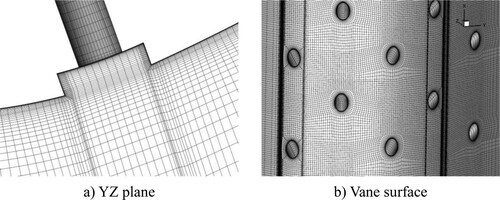
The mesh of the fluid computational domain is shown in Figure . The O-type mesh topology is applied around the C3X vane and cooling holes to improve the mesh quality. For example, Figure shows the mesh of Case 1 with round cooling holes and Figure presents the mesh of Case 2 with the trench. The O-type topology is also employed to obtain a better mesh transition of the trench lip.
Figure 4. The mesh of the turbine vane.
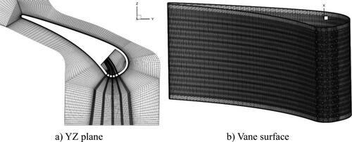
Figure 5. The mesh for trenched holes on the LE.
The solid domains of TBC and metal use the unstructured mesh, as shown in Figure . The grid number of the TBC and metal domain is about 1 million and 5 million, respectively.
Figure 6. The mesh of solid domain for aero-thermal coupling calculation.
2.4. Numerical validation
The heat transfer coefficient in the experiment is calculated by:
Numerical methods are widely used to simulate heat transfer characteristics (Ez Abadi et al., Citation2020; Ramezanizadeh et al., Citation2019), especially RANS turbulence model. Figure shows the prediction results of different RANS turbulence models at the middle span of the C3X guide vane. The heat transfer coefficient reaches a peak near X/L = 0 of the SS side. Then the heat transfer coefficient begins to decrease and reaches a low value near X/L = 0.45 due to the boundary layer transition. Further downstream, the heat transfer coefficient begins to increase again. The results of turbulence model with the transition equation fit better with the experimental heat transfer coefficient, where model especially has a good prediction for the transition position and the experimental value. This means that
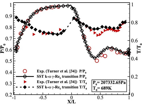
model can simulate the important feature of turbulence transition for the C3X vane. On the PS side, although the turbulence models without transition model can predict the increased heat transfer coefficient well in the X/L < −0.5 region, the turbulence models with the transition model has a good prediction in the −0.5 < X/L < 0 region. However, it need to be mentioned that this paper mainly focuses on the region near the LE. Besides, as shown in Figure , the pressure and temperature distribution by the
model is consistent with the experimental results well. Therefore, this model is used to conduct the following simulation.
Figure 7. Distributions of heat transfer coefficient on the vane surface by different RANS models.
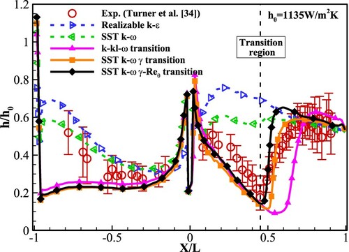
Figure 8. Comparison of the pressure and temperature distributions on the vane.
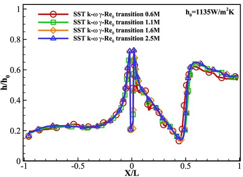
For grid independence, the heat transfer coefficient calculated by 6, 11, 16, and 25 million grid number is shown in Figure . The different mesh numbers are achieved by changing the mainstream node number of the X-, Y-, and Z- direction and the nodes in the film cooling holes. It can be seen that when the grid increases to 16 million, the distribution of the heat transfer coefficient will not change as grid number increases. Therefore, the 16-million grid will be used in the following calculation.
Figure 9. Grid independence validation.
In the simulation, the discretization of convection term adopts the second-order upwind scheme. The convergence criterion of the solution is as follows. The residual of continuity and energy was kept below 10−4 and 10−8, respectively. All other residuals were below at least 10−5.
3. Results and discussion
3.1. Film cooling performance
In this section, the coolant inlet mass flow is maintained at 0.00171 kg/s for both five-row and three-row showerhead cooling design. Table shows the coolant mass flow distribution and the averaged blowing ratio for each row of showerhead holes. The locations of the trenched holes are marked in bold. Figure shows the distribution of the ηL in the LE region of −30 < S/D < 30 at = 0.00171 kg/s. The integration for calculating the ηL is carried out over the whole blade height. On the PS side, the ηL is almost 0 in the −8 < S/D < 0 area for Case 1 and Case 2 with five rows of showerhead holes. Then, the ηL starts to rise in the S/D < −8 region and the coolant works effectively in this region of the PS side, especially for trenched Case 2. On the SS side, the ηL of Case 1 and Case 2 steps up with the coolant moving downstream, due to the coolant superimposed effect. In the region of 4 < S/D < 8, the SS side trenched holes of Case 2 bring a higher cooling performance than the round holes of Case 1, however, the ηL of Case 2 is slightly lower in the area of S/D > 8. This is because the trenched holes of Case 2 make the coolant more concentrated near the holes. Therefore, the supplementary effect of the upstream coolant weakens, compared with Case 1. In terms of ηS distributions, the ηS in the 0 < S/D < 30 region of the SS side is 0.247 and 0.249 for Case 1 and Case 2 respectively. Therefore, the arrangement of trenched holes only changes the downstream local effectiveness distributions. The overall improvement of trenched holes is limited on the SS side. On the PS side, ηS in the −30 < S/D < 0 region is 0.080 and 0.131 for Case 1 and Case 2 respectively, which shows more improvement of overall effectiveness than the SS side.
Figure 10. Influence of different LE cooling structures on ηL.
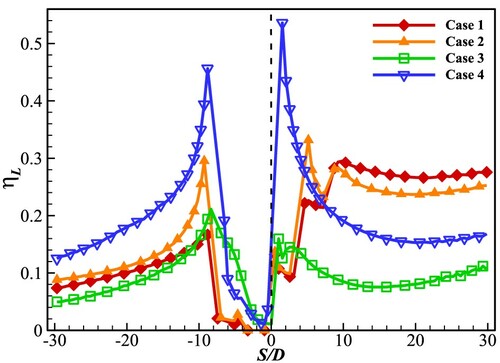
Table 5. Coolant mass flow distributions and average blowing ratios for LE holes.
As shown in Figure , for Case 3 and Case 4, there is still a low ηL region near S/D = 0 region. In spite of this, the coolant in two rows of holes mainly flows towards the PS side, dramatically improving the ηL in the region of −10 < S/D < −2. Meanwhile, the trenched holes in Case 4 bring a significant ηL improvement and the ηL nearly doubles in the most LE region. Compared with the five-row designs of Case 1 and Case 2, although the hole inclined angle of Case 3 has been reduced, the ηL is lower than that of the Case 1 with five-row round holes in most LE areas. In contrast, Case 4 with the trenched holes presents higher ηL than the other three showerhead cooling design, except in the S/D > 9 region. The lower ηL of the Case 4 cooling design in the area of S/D > 9 is caused by the less coolant distribution of the SS side and this can be solved by another arrangement of trenched holes.
Figure shows the η contours on the LE. In Table , the blowing ratio of the first row on the PS side is about 0.4, and the coolant is mainly distributed on the PS side. The blowing ratio of the stagnation-line row is about 0.5, and the coolant is distributed towards the SS side. For the local η distributions of both Case 1 and Case 2, an obvious coolant lift-off from the wall can be seen downstream of the first row on the PS side. It means that the coolant from the PS-side holes is easier to penetrate the mainstream. Meanwhile, the downstream coolant cannot reattach to the surface on the PS side, due to the normal pressure distribution and changes of curvature in the region. The trenched holes of Case 2 can provide orientation and protection for the coolant in the trench, leading to a more distributed coolant coverage downstream of the holes. The improvement of coolant coverage can avoid direct hot erosion and reduce local thermal stress and ablation.
Figure 11. Influence of different showerhead cooling holes on local η distributions on the LE region.
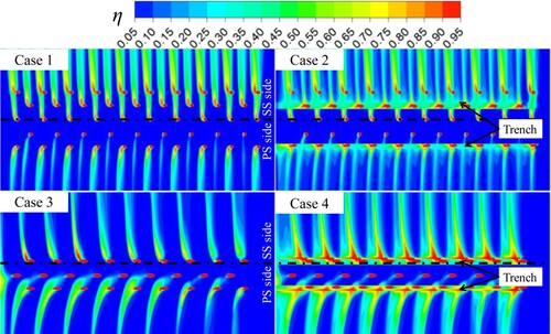
Similarly, for Case 3 and Case 4 with three rows of showerhead holes, the trenched holes still bring a significant increase in the lateral coolant coverage. Especially, due to the fewer rows of showerhead holes in Case 3, the improvement of trenched holes is more obvious than the five-row cooling design. It is worth noting that there is a certain difference between the actual stagnation line and the geometric stagnation line on the blade surface, and the actual stagnation line is also somewhat changing due to different working conditions. This leads to a bad coolant coverage region near the stagnation line under some working conditions. In order to avoid excessive local thermal load, more dense holes need to be arranged in this area, and higher requirements are put forward for the internal cooling design.
3.2. Analysis of flow field
Figures and show the streamline and θ > 0.05 distributions on the plane normal to the blade surface. The streamlines are also colored by the non-dimensional temperature. For the PS side (Figure ), the curvature change leads to obvious coolant lift-up as the coolant from the first row on the PS side travels from S/D = −6 to S/D = −10. Besides, the high inclined angle of 45° also worsens the situation. By comparison, the lift-up of the coolant from the second PS-side row weakens, because the downstream coolant jet faces the concave wall and it can benefit jet attachment. In spite of this, the coolant core of the round holes completely detaches from the wall due to the high normal momentum and nearby pressure gradient. In contrast, the trenched holes in Case 2 guarantee the attachment of the coolant core. Meanwhile, the high normal momentum of the coolant still leads to the obvious penetration into the mainstream due to the large inclined angle. In respect of the issues above, the smaller inclined angle is employed in Case 3 and Case 4 so that the coolant extends a certain distance in the spanwise direction before flowing towards the PS side. This arrangement results in better coolant coverage between adjacent holes. It can be inferred that the coolant accumulation along the stagnation line can further improve the performance of coolant coverage at a higher blowing ratio. Besides, the coolant core of the first row on the PS side is just above the coolant trajectory of the second row. It has been concluded that the detrimental vortex exists downstream of the trenched holes of the 90° compound angle (Hou, Wen, Tang, et al., Citation2019; Hou, Wen, Wang, et al., Citation2019). This leads to the more obvious penetration of the coolant for both Case 3 and Case 4. Therefore, the hole arrangement can be further optimized in order to achieve the effective coolant supplement and less impact of the detrimental vortices.
Figure 12. Streamline and non-dimensional temperature distributions on the PS side.
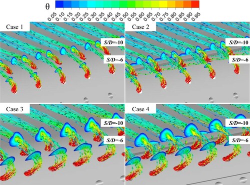
Figure 13. Streamline and non-dimensional temperature distributions on the SS side.
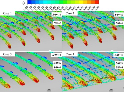
In Table , the averaged blowing ratio of SS side each row is higher than the PS side for five-row showerhead design. However, as shown in Figure , the SS-side coolant presents more attachment to the wall at a higher blowing ratio. This means that a higher SS cooling performance can be obtained at a higher blowing ratio. In the three-row cooling design, one row of holes with a 25° inclined angle is employed to replace the three rows in Case 1 and Case 2. Especially in Case 4, the trenched holes can ensure the lateral coverage on the SS side. As seen from the non-dimensional temperature on the planes from S/D = 4 to S/D = 10, the mixing of the coolant is slow in the mainstream streamwise direction. The coolant coverage region at S/D is equivalent to that of Case 1, but inferior to the Case 2 with trenched holes.
3.3. Effects of blowing ratio
The impact of Mave,LE on the LE film cooling will be discussed in this part. At same blowing ratio, the inlet coolant mass flow of three-row cooling design is lower than that of the five-row cooling design, as presented in Table . As shown in Figure , for Case 1, the increase of Mave,LE, aggravates the coolant lift-up, and the ηL further decreases near S/D = 0. The trenched holes in Case 2 also cannot avoid the coolant mixing and guarantee the lateral expansion of the coolant. At Mave,LE = 1.3, the ηL of Case 2 also declined obviously. It can be inferred that a larger inclined angle will narrow the range of the effective blowing ratios. Hence, this section only includes the blowing of Mave,LE = 0.8, and 1.3 for Case 1 and Case 2. Besides, the 0.5D trench width is employed in the present study, considering the LE wall thickness. However, it has been proved that the 0.75D trench width provides higher film cooling performance, as mentioned in the Introduction. Therefore, the hole diameter can be reduced in order to improve cooling performance.
Figure 14. Distributions of LE ηL at different blowing ratios.
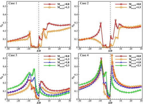
For the three-row showerhead holes of Case 3 and 4, as Mave,LE increases, the ηL near the stagnation line is first reduced and then increased in the −7 < S/D < −4.5 region of the PS side. At Mave,LE = 1.3, the ηL reaches the peak. The ηL in the −2.5 < S/D < −0.5 is slightly improved at a higher blowing ratio. This is because the lateral extension of coolant is enhanced at the lower normal momentum and the higher lateral momentum when the coolant is injected from showerhead holes with a lower inclined angle of 25°. While the coolant flow develops laterally and reaches the adjacent cooling hole, it suppresses the coolant lift-up and plays a supplement role. Therefore, the higher ηL is shown at a higher blowing ratio. The coolant jet from the PS-side second row is affected by upstream flow. Its ηL begins to rise at Mave,LE = 1.3. On the SS side, the ηL of Case 3 decreases at a higher Mave,LE. At Mave,LE = 2.3, the ηL is close to 0. This indicates that the coolant from the SS-side holes is adversely affected by the convex wall surface, the mainstream acceleration, and higher mainstream momentum. These flow conditions are not beneficial to the coolant attachment and lateral extension. For Case 4, the ηL downstream of PS-side trenched holes is not influenced obviously by the blowing ratio On the SS side, the higher ηL can be obtained at Mave,LE = 0.8-1.8. Then, the ηL begins to decline obviously at Mave,LE = 2.3. Considering the ηL distribution on the PS and SS side, the three-row cooling design with trenched holes can guarantee the higher ηL in a wider range of blowing ratio. Besides, it can also obtain higher ηL at a smaller coolant mass flow, compared with five-row cooling design.
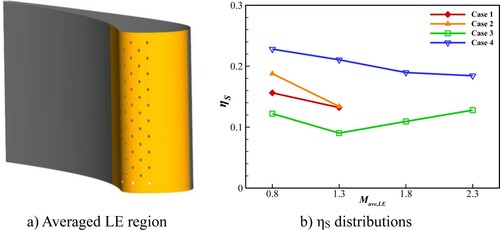
Figure shows the ηS distributions in the LE region in order to further quantitatively compare the coolant coverage performance. The ηS is averaged in the region of −30 < S/D < 30, as the LE area with the orange color shows in Figure (a). Case 4 with trenched holes presents the highest ηS. At Mave,LE = 0.8, the ηS presents the highest value. Compared with Case 3, the improvement of trenched holes in Case 4 is obvious. Case 4 can achieve the goals of a higher cooling performance with a lower coolant mass flow and manufacturing cost, when compared with other cases.
Figure 15. ηS distributions on the LE region.
3.4. Aerodynamic losses
The mixing loss of film cooling is evaluated by the total pressure loss coefficient Cp, which is defined as (He et al., Citation2019):
Where
is the mass averaged total pressure at a distance of 5D away from the turbine trailing edge. Figure shows the Cp distribution at different b lowing ratios for different showerhead cooling design. There is a little Cp differential between Case 1 and 2 at Mave,LE = 0.8. With blowing ratio increasing to Mave,LE = 1.3, the Cp of Case 2 with trenched holes is even lower than that of Case 1. For the three-row cooling design of Case 3 and Case 4, the Cp also rises while Mave,LE increases from 0.8 to 2.3. The cooling performance of Case 4 is not only higher than Case 3 at different blowing ratios, but also its aerodynamic loss of trenched holes is lower
Figure 16. Distributions of total pressure loss coefficient.
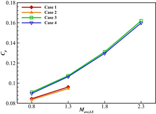
Meanwhile, even though the cooling, the aerodynamic loss of trenched holes in Case 4 is lower than Case 3. Therefore, the LE trenched holes are beneficial to the reduction of total pressure coefficient by coolant mixing. In addition, under the same coolant inlet mass flow, the total pressure loss by the three-row showerhead cooling design is higher than five-row showerhead holes, after comparing the blowing ratios of Mave,LE = 0.8 for Case 1 and Case 2 and Mave,LE = 1.3 for Case 3 and Case 4.
3.5. Aero-thermal coupled calculation
In the aero-thermal coupled calculation, the non-dimensional temperature of TBC and metal are defined as τ and φ, respectively:
Where
and
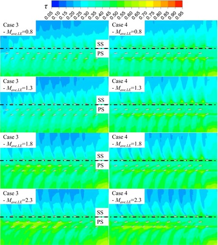
is the temperature of the TBC and metal surface, respectively. In the aero-thermal calculation, a higher thermal resistance of the solid domain would lead to the lower value of Bi number. The temperature on the TBC surface with a lower thermal conductivity will tend to the temperature distribution of adiabatic simulation. The adiabatic η mainly presents the ability of the film coverage. By comparison, the coupled calculation also considers the internal cooling effects of the plenum, besides the cooling performance of the external surface. According to the discussion above, it can be concluded the three-row cooling design with trenched holes can replace the five-row showerhead holes. In addition, to control the internal cooling influences, this section only chooses Case 3 and Case 4 to conduct the following aero-thermal coupling study. Figure shows the laterally averaged non-dimensional temperature distributions on the TBC surface. For Case 3, the changed blowing ratios in the coupled calculation mainly exerted more influence on the τL distribution of the PS side, referring to the region of −23 < S/D < 0. For Case 4, the impact of the blowing ratio can be seen on both SS and PS side, referring to −23 < S/D < 30. The less influence in the region of −30 < S/D < −23 lies on the different coolant mass flow between different plenum. On the SS side, the adiabatic ηL of Case 3 is much lower than Case 4 as shown in Figure . The adiabatic effectiveness of Case 3 first increases and then falls on the SS side at higher blowing ratio. In contrast, the increased blowing ratio improves the internal cooling ability, which offsets the adverse effect of the changed external film cooling performance. This results in the small difference of τL distributions on the SS side in the aero-thermal coupled calculation, as shown in Figure . Comparing Case 3 and Case 4 in the region of −7 < S/D < 0, the τL distribution of Case 3 is more influenced by the blowing ratios. Although the influence of the blowing ratio weakens in the −7 < S/D < 0 region in the coupled calculation, the trend of the changed τL distribution accords with the adiabatic results. In the specified blowing ratio, the significant change of adiabatic ηL can also be reflected in the coupled result.
Figure 17. LE laterally averaged non-dimensional temperature for the aero-thermal calculation.
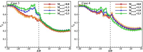
Figure shows the local τ distributions on the TBC surface. Firstly for the LE SS side, the temperature distribution of aero-thermal coupled calculation is more uniform than that of the adiabatic simulation in Figure . Nevertheless, Case 4 with trenched holes can provide larger coolant coverage than Case 3 at Mave,LE = 0.8, 1.3 and 1.8. Meanwhile, the difference between Case 3 and Case 4 narrows in the aero-thermal coupled calculation, for example, compare the condition of Mave,LE = 1.3 in Figures and . At Mave,LE = 2.3, the adiabatic ηL begins to decline, leading to less improvement of trenched holes on the SS side. It can be inferred that the larger temperature difference in the adiabatic calculation can only be reflected when the adiabatic improves obviously in a large region. Otherwise, the high thermal conductivity of the solid domain and the internal cooling would erase the effect of changes in adiabatic cooling performance. The discussion above is also appropriate to the PS side. The improvement of Case 4 in the aero-thermal calculation is more obvious at Mave,LE = 0.8 and 1.3 on the PS side. In addition, even if Case 4 peels off a part of TBC on the blade surface to form the transverse trench, a local high temperature does not appear on the LE area because of the coolant filling in the trench.
Figure 18. τ contours on the TBC surface of the LE region.
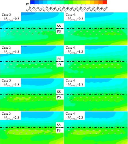
On the other hand, Figure presents the local φ distribution on the metal surface. Compared with the non-dimensional temperature distribution on the TBC surface in Figure , the non-dimensional distribution is more uniform on the metal surface because of its lower thermal resistance. Besides, the downward distribution trend along the stagnation line conforms to the coolant flow direction in the plenum. The trenched holes in Case 4 provide a higher φ distribution than Case 3 at Mave, LE = 0.8 and 1.3, because of the higher cooling performance on the TBC surface. However, both the temperature difference and blowing ratio range narrows at a higher blowing ratio, after comparing the non-dimensional temperature distributions in Figures and . This is because of the smaller film cooling difference and higher internal coolant mass flow, especially at Mave, LE = 2.3.
Figure 19. contours on the metal surface of the LE region.
4. Conclusion
The investigation of showerhead film cooling is conducted in the present study, including adiabatic calculation and aero-thermal coupled calculation.
At coolant mass flow of 0.00171 kg/s, the five-row showerhead holes with a 45° inclined angle cannot provide an efficient coolant coverage in the LE region of −8 < S/D < 0. On the SS side, because of the coolant superimposed effect, the ηL steps up after the coolant flows over one row of cooling holes. After arranging trenched holes on the LE region, the lateral extension of the coolant improves, and more coolant is accumulated nearby the trench to guarantee the film coverage. By comparison, the ηL of three-row holes without trench is significantly lower than five-row cooling design. However, the arrangement of trenched holes in the three-row cooling design provides an obvious improvement of cooling performance. Especially, its ηL is higher than five-row showerhead holes in most of the showerhead region.
In terms of the influence of the blowing ratios, the higher blowing ratio would aggravate the LE coolant coverage for five-row showerhead design. For the three-row design, with the increased blowing ratio, the ηL decreases on the SS side. By comparison, ηL of the PS side decreases first and then increases. The trenched holes in the three-row cooling design shows better cooling performance within Mave, LE = 0.8-1.8 on the SS side, while on the PS side, it can cover a larger range of blowing ratio from 0.8 to 2.3. In addition, for both five-row and three-row cooling design, the introduction of trenched holes not only brings the additional aerodynamic losses but also reduces mixing losses at a higher blowing ratio.
In the aero-thermal coupled simulation, the temperature distribution on the TBC surface more conforms to the adiabatic result, compared with the distribution on the metal surface. The trenched holes in the three-row cooling design can reduce the temperature of the TBC surface at Mave, LE = 0.8 and 1.3, which is narrower than the results of the adiabatic calculation. Besides, the trench, splitting a part of TBC on the surface, would not lead to the local high temperature region, because of the coolant filling. The present study mainly focuses on the straight turbine leading-edge configuration by the numerical method. In the future, the trenched cooling holes will be investigated for the bowed and twisted blade and its arrangement should be considered. In addition, the experimental investigation should be conduct, based on the present study.
Disclosure statement
No potential conflict of interest was reported by the author(s).
Additional information
Funding
References
- Albert, J. E., & Bogard, D. G. (2013). Measurements of adiabatic film and overall cooling effectiveness on a turbine vane pressure side with a trench. Journal of Turbomachinery, 135(5), Article 051007. https://doi.org/https://doi.org/10.1115/1.4007820
- An, B., Liu, J., & Jiang, H. (2005). Numerical investigation of film cooling in an air cooled turbine stator. Journal of Engineering Thermophysics, 26(3), 405–408.
- Barigozzi, G., Franchini, G., Perdichizzi, A., & Ravelli, S. (2012). Effects of trenched holes on film cooling of a contoured endwall nozzle vane. Journal of Turbomachinery, 134(4), Article 041009. https://doi.org/https://doi.org/10.1115/1.4003658
- Bunker, R. S. (2002, June 3–6). Film cooling effectiveness due to discrete holes within a transverse surface slot. Proceedings of the ASME Turbo Expo 2002: Power for land, sea, and air. Amsterdam, The Netherlands. https://doi.org/https://doi.org/10.1115/GT2002-30178.
- Davidson, F. T., Dees, J. E., & Bogard, D. G. (2011, June 6–10). An experimental study of thermal barrier coatings and film cooling on an internally cooled simulated turbine vane. Proceedings of the ASME 2011 Turbo Expo: Turbine Technical Conference and Exposition. Vancouver, BC, Canada. https://doi.org/https://doi.org/10.1115/GT2011-46604.
- Dong, P. (2009). Research on conjugate heat transfer simulation of aero turbine engine air-cooled vane (Dissertation, Harbin Institute of Technology).
- Dorrington, J. R., Bogard, D. G., & Bunker, R. S. (2007, May 14–17). Film effectiveness performance for coolant holes imbedded in various shallow trench and crater depressions. Proceedings of the ASME Turbo Expo 2007: Power for land, sea, and air. Montreal, Canada. https://doi.org/https://doi.org/10.1115/GT2007-27992.
- Du, K., Song, L., Li, J., & Sunden, B. (2017). Effects of the layout of film holes near the vane leading edge on the endwall cooling and phantom cooling of the vane suction side surface. Numerical Heat Transfer, Part A: Applications, 71(9), 910–927. https://doi.org/https://doi.org/10.1080/10407782.2017.1326788
- Elnady, T., Hassan, I., Kadem, L., & Lucas, T. (2013). Cooling effectiveness of shaped film holes for leading edge. Experimental Thermal and Fluid Science, 44, 649–661. https://doi.org/https://doi.org/10.1016/j.expthermflusci.2012.09.005
- Ez Abadi, A. M., Sadi, M., Farzaneh-Gord, M., Ahmadi, M. H., Kumar, R., & Chau, K. (2020). A numerical and experimental study on the energy efficiency of a regenerative heat and mass exchanger utilizing the counter-flow Maisotsenko cycle. Engineering Applications of Computational Fluid Mechanics, 14(1), 1–12. https://doi.org/https://doi.org/10.1080/19942060.2019.1617193
- Feuerstein, A., Knapp, J., Taylor, T., Ashary, A., Bolcavage, A., & Hitchman, N. (2008). Technical and economical aspects of current thermal barrier coating systems for gas turbine engines by thermal spray and EBPVD: A review. Journal of Thermal Spray Technology, 17(2), 199–213. https://doi.org/https://doi.org/10.1007/s11666-007-9148-y
- Gao, Z., & Han, J. (2009). Influence of film-hole shape and angle on showerhead film cooling using PSP technique. Journal of Heat Transfer, 131(6), Article 061701. https://doi.org/https://doi.org/10.1115/1.3082413
- Gao, W., Yue, Z., Li, L., Zhao, Z., & Tong, F. (2017). Numerical simulation on film cooling with compound angle of blade leading edge model for gas turbine. International Journal of Heat and Mass Transfer, 115, 839–855. https://doi.org/https://doi.org/10.1016/j.ijheatmasstransfer.2017.07.105
- Harrison, K. L., Dorrington, J. R., Dees, J. E., Bogard, D. G., & Bunker, R. S. (2009). Turbine airfoil net heat flux reduction with cylindrical holes embedded in a transverse trench. Journal of Turbomachinery, 131(1), Article 011012. https://doi.org/https://doi.org/10.1115/1.2812967
- He, W., Deng, Q., Zhou, W., Gao, T., & Feng, Z. (2019). Film cooling and aerodynamic performances of a turbine nozzle guide vane with trenched cooling holes. Applied Thermal Engineering, 150, 150–163. https://doi.org/https://doi.org/10.1016/j.applthermaleng.2019.01.002
- Hou, R., Wen, F., Tang, X., Cui, T., & Wang, S. (2019). Improvement of film cooling performance by trenched holes on turbine leading-edge models. Numerical Heat Transfer, Part a: Applications, 76(3), 160–177. https://doi.org/https://doi.org/10.1080/10407782.2019.1627832
- Hou, R., Wen, F., Wang, S., Luo, Y., & Tang, X. (2019). Large eddy simulation of the trenched film cooling hole with different compound angles and coolant inflow orientation effects. Applied Thermal Engineering, 163, 114397. https://doi.org/https://doi.org/10.1016/j.applthermaleng.2019.114397
- Hylton, L. D., Milhec, M. S., Turner, E. R., Nealy, D. A., & York, R. E. (1983). Analytical and experimental evaluation of the heat transfer distribution over the surface of turbine vanes (NASA-CR-168015). https://ntrs.nasa.gov/citations/19830020105.
- Islami, S. B., Tabrizi, S. P. A., & Jubran, B. A. (2007). Computational investigation of film cooling from trenched holes near the leading edge of a turbine blade. Numerical Heat Transfer, Part A: Applications, 53(3), 308–322. https://doi.org/https://doi.org/10.1080/10407780701564200
- Khalatov, A. A., Panchenko, N. A., Borisov, I. I., & Severina, V. V. (2017). Numerical simulation of film cooling with a coolant supplied through holes in a trench. Journal of Engineering Physics and Thermophysics, 90(3), 637–643. https://doi.org/https://doi.org/10.1007/s10891-017-1610-1
- Kim, Y. J., & Kim, S.-M. (2004). Influence of shaped injection holes on turbine blade leading edge film cooling. International Journal of Heat and Mass Transfer, 47(2), 245–256. https://doi.org/https://doi.org/10.1016/j.ijheatmasstransfer.2003.07.008
- Lee, K.-D., & Kim, K.-Y. (2014). Film cooling performance of cylindrical holes embedded in a transverse trench. Numerical Heat Transfer, Part A: Applications, 65(2), 127–143. https://doi.org/https://doi.org/10.1080/10407782.2013.826106
- Li, H., Han, F., Ma, Y., Wang, H., Zhou, Z., & Tao, Z. (2019). Experimental investigation on the effects of rotation and the blowing ratio on the leading-edge film cooling of a twist turbine blade. International Journal of Heat and Mass Transfer, 129, 47–58. https://doi.org/https://doi.org/10.1016/j.ijheatmasstransfer.2018.09.005
- Li, S. J., Yang, S. F., & Han, J. C. (2014). Effect of coolant density on leading edge showerhead film cooling using the pressure sensitive paint measurement technique. Journal of Turbomachinery, 136(5), Article 051011. https://doi.org/https://doi.org/10.1115/1.4025225
- Liu, Z., Ye, L., Wang, C., & Feng, Z. (2014). Numerical simulation on impingement and film composite cooling of blade leading edge model for gas turbine. Applied Thermal Engineering, 73(2), 1432–1443. https://doi.org/https://doi.org/10.1016/j.applthermaleng.2014.05.060
- Liu, C., Zhu, H., Zhang, X., Xu, D., & Zhang, Z. (2014). Experimental investigation on the leading edge film cooling of cylindrical and laid-back holes with different radial angles. International Journal of Heat and Mass Transfer, 71, 615–625. https://doi.org/https://doi.org/10.1016/j.ijheatmasstransfer.2013.12.050
- Lu, Y., Dhungel, A., Ekkad, S. V., & Bunker, R. S. (2009). Effect of trench width and depth on film cooling from cylindrical holes embedded in trenches. Journal of Turbomachinery, 131(1), Article 011003. https://doi.org/https://doi.org/10.1115/1.2950057
- Lu, Y., Nasir, H., & Ekkad, S. V. (2005, June 6–9). Film cooling from a row of holes embedded in transverse slots. Proceedings of the ASME Turbo Expo 2005: Power for land, sea, and air. Reno, NV, USA. https://doi.org/https://doi.org/10.1115/GT2005-68598.
- Maikell, J., Bogard, D., Piggush, J., & Kohli, A. (2011). Experimental simulation of a film cooled turbine blade leading edge including thermal barrier coating effects. Journal of Turbomachinery, 133(1), Article 011014. https://doi.org/https://doi.org/10.1115/1.4000537
- Mouzon, B. D., Terrell, E. J., Albert, J. E., & Bogard, D. G. (2005, June 6–9). Net heat flux reduction and overall effectiveness for a turbine blade leading edge. Proceedings of the ASME Turbo Expo 2005: Power for land, sea, and air. Reno, NV, USA. https://doi.org/https://doi.org/10.1115/GT2005-69002.
- Nathan, M. L., Dyson, T. E., Bogard, D. G., & Bradshaw, S. D. (2014). Adiabatic and overall effectiveness for the showerhead film cooling of a turbine vane. Journal of Turbomachinery, 136(3), Article 031005. https://doi.org/https://doi.org/10.1115/1.4024680
- Polanka, M. D., Witteveld, V. C., & Bogard, D. G. (1999, June 7–10). Film cooling effectiveness in the showerhead region of a gas turbine vane: Part I – Stagnation region and near-pressure side. Proceedings of the ASME 1999 International Gas Turbine and Aeroengine Congress and Exhibition. Indianapolis, IN, USA. https://doi.org/https://doi.org/10.1115/99-GT-048.
- Ramezanizadeh, M., Alhuyi Nazari, M., Ahmadi, M. H., & Chau, K. (2019). Experimental and numerical analysis of a nanofluidic thermosyphon heat exchanger. Engineering Applications of Computational Fluid Mechanics, 13(1), 40–47. https://doi.org/https://doi.org/10.1080/19942060.2018.1518272
- Ravi, D., & Parammasivam, K. (2019). Enhancing film cooling effectiveness in a gas turbine end-wall with a passive semi cylindrical trench. Thermal Science, 23(3), 2013–2023. https://doi.org/https://doi.org/10.2298/TSCI170412001R
- Taslim, M. E., & Khanicheh, A. (2006). Experimental and numerical study of impingement on an airfoil leading edge with and without showerhead and gill film holes. Journal of Turbomachinery, 128(2), 310–320. https://doi.org/https://doi.org/10.1115/1.2137742
- Turner, E. R., Wilson, M. D., Hylton, L. D., & Kaufman, R. M. (July 1/1985). Analytical and experimental evaluation of surface heat transfer distributions with leading edge showerhead film cooling (NASA-CR-174827). https://ntrs.nasa.gov/citations/19860012075.
- Waye, S. K., & Bogard, D. G. (2007). High-resolution film cooling effectiveness measurements of axial holes embedded in a transverse trench with various trench configurations. Journal of Turbomachinery, 129(2), 294–302. https://doi.org/https://doi.org/10.1115/1.2464141
- Witteveld, V. C., Polanka, M. D., & Bogard, D. G. (1999, June 7–10). Film cooling effectiveness in the showerhead region of a gas turbine vane: Part II – Stagnation region and near-suction side. Proceedings of the ASME 1999 International Gas Turbine and Aeroengine Congress and Exhibition. Indianapolis, IN, USA. https://doi.org/https://doi.org/10.1115/99-GT-049.
- Ye, L., Liu, C., Liu, F., Yang, Y., & Zhu, H. (2020). Experimental study on heat transfer of leading edge film-cooling with counter-inclined cylindrical and laid-back holes. Journal of Heat Transfer, 142(6), Article 061801. https://doi.org/https://doi.org/10.1115/1.4046529
- York, W. D., & Leylek, J. H. (2002, June 3–6). Leading-edge film-cooling physics: Part I – Adiabatic effectiveness. Proceedings of the ASME Turbo Expo 2002: Power for land, sea, and air. Amsterdam, The Netherlands. https://doi.org/https://doi.org/10.1115/GT2002-30166.
- Zhang, L. J., & Pudupatty, R. (2000, May 8–11). The effects of injection angle and hole exit shape on turbine nozzle pressure side film cooling. Proceedings of the ASME Turbo Expro 2000: Power for land, sea, and air. Munich, Germany. https://doi.org/https://doi.org/10.1115/2000-GT-0247.
- Zhang, B., Zhu, H., Liu, C., & Wei, J. (2020). Experimental study on the film-cooling characteristics of the cylindrical holes embedded in sine-wave shaped trench. Journal of Engineering for Gas Turbines and Power, 142(10), Article 101003. https://doi.org/https://doi.org/10.1115/1.4048326