
 ?Mathematical formulae have been encoded as MathML and are displayed in this HTML version using MathJax in order to improve their display. Uncheck the box to turn MathJax off. This feature requires Javascript. Click on a formula to zoom.
ABSTRACT
The magnetically assisted resistance spot welding (MA-RSW) method provides a promising approach for improving weld performance. However, the MA-RSW process involves complex multiphysics fields that make numerical modeling very challenging. Thus, most resistance spot welding (RSW) models adopt electrothermal-mechanical coupling and ignore the influence of fluid flows caused by electromagnetic forces on nugget growth. In this paper, a magnetohydrodynamic (MHD) model, which couples the electric, thermal, magnetic and flow fields, is developed to explore the influencing mechanism of an external magnetic field (EMF) on the flow patterns and microstructures of aluminum resistance spot welds. Numerical results show that the application of an EMF can lead to the formation of Lorentz force in the liquid nugget, which transforms the flow pattern from an in-plane flow to a combined in-plane and out-of-plane flow. The flow velocity of molten metal in the MA-RSW process is 5 times higher than that of the RSW process, and the maximum temperature of the MA-RSW model is reduced from 774°C in the MHD RSW model to 725°C. Therefore, the MA-RSW joint exhibits a 25.5% larger nugget diameter, a more than 20% finer grain structure, and fewer defects than the RSW joint in the experimental results.
1. Introduction
Resistance spot welding (RSW) is an important joining method in automobile, locomotive and aerospace industries (Wei & Wu, Citation2012) because of its high efficiency, low cost and high automation properties (Florea et al., Citation2012). As lightweight materials that promote energy savings and emission reductions, aluminum alloys have been widely used because of their low density, high specific strength and good corrosion resistance (Kang et al., Citation2016). However, aluminum alloy has a lower electrical resistivity, higher thermal conductivity and lower electrical resistivity than steel, which makes it necessary to use 3–5 times the welding current when compared with steel RSW. The high centralized instantaneous heat input increases the risk of early expulsion, hot cracks, shrinkage cavities, and insufficient nugget diameters, resulting in low weld performance (Wang et al., Citation2019).
To improve the weld quality in a energy-efficient method, magnetically assisted resistance spot welding (MA-RSW) technology was proposed by Shen et al. (Citation2011). Experimental studies on dual-phase steel (Qi et al., Citation2020), stainless steel (Li et al., Citation2018), aluminum alloy (Huang et al., Citation2020), magnesium alloy (Yao et al., Citation2014) and Al/Ti dissimilar materials (Li et al., Citation2015) have shown that an external magnetic field (EMF) can enlarge the nugget size, reduce the shrinkage defects, and improve the mechanical performance of weld joints. However, these studies were based on experimental methods, and the control mechanism of an EMF on the flow behaviors of molten metal cannot be observed because the weld formation process is completely invisible, which limits further improvement of the weldperformance.
Numerical modeling is a mainstream method used for exploring the multiphysics mechanism inside an enclosed weld nugget. However, most of the existing RSW numerical models have neglected the fluid flow caused by the induced magnetic field (IMF) due to the extreme complexity of the multiphysics model, and they could not truly reveal the temperature evolution nature during nugget growth (Bi et al., Citation2016; Deng et al., Citation2020; Moshayedi & Sattarifar, Citation2012; Wan et al., Citation2016). To understand the magnetohydrodynamic (MHD) behavior in liquid nuggets, Wei et al. (Citation1996) pioneered the study of unsteady transport phenomena in RSW by using a 2D finite-difference model. Li et al. (Citation2007) proposed a multiphysical finite element model to study the MHD behaviors in the mild steel RSW process. Both models for the RSW process showed that the Lorentz force resulting from the interaction of the welding current and its IMF has an important influence on nugget growth and temperature distribution.
However, the abovementioned models were for the steel RSW process, and there is no research on the effect of an IMF on the flow and heat transfer behavior of aluminum alloy materials in the RSW process. Furthermore, the effect of the EMF on the MA-RSW process remains unclear. In the MA-RSW process, the existing 2D model is no longer applicable because the external electromagnetic field is three-dimensional in nature. In addition, differing from the coupling mechanism of thermo-electro-structural fields in most of the previous studies, the complexity of the coupling mechanism of the MA-RSW model is greatly increased when the EMF and flow field are considered. In recent years, computer fluid dynamics (CFD) has been an important means for modeling various complex phenomena (Abadi et al., Citation2020; Granados-Ortiz et al., Citation2021). For example, Ramezanizadeh et al. (Citation2019) used CFD to investigate the heat transfer of nanofluidic thermosyphon heat exchangers. Therefore, how to couple electric and magnetic fields in a CFD model is the major difficulty and challenge in this research. To this end, a more complex model is needed to investigate the MHD behaviors in the MA-RSW process.
In this study, a 3D numerical model is established using ANSYS software to simulate the MA-RSW process of aluminum alloy. This model constructs a four-field coupling mechanism of electrical, thermal, magnetic and flow fields. Physical measurements of the EMF and weld profile are used to validate the model. Contrastive analyses throughout the RSW and MA-RSW processes are performed in terms of the magnetic field, magnetic force distribution, flow pattern, and temperature field. Finally, the influencing mechanism of the EMF on the weld macromorphology and microstructure is discussed based on experimentation and simulations.
2. Numerical model
2.1. Governing equations
The MHD behaviors in MA-RSW are very complex due to the combined action of both an IMF and an EMF. To reduce the model complexity and improve the calculation efficiency, the following assumptions are made:
During the heating and melting process, the density of workpieces does not change with temperature and pressure (Li et al., Citation2007).
The charge density
of molten metal in the nugget is equal to zero (Li et al., Citation2011).
The gravity effects on fluid flow in nuggets can be ignored due to short welding times in the MA-RSW process (Khan et al., Citation2000).
The density of the workpieces does not change during the phase transformation process.
Viscous stress exists between the liquid fluid particles, and there is no slip velocity at the solid–liquid phase boundary (Li et al., Citation2011).
The solute diffusion effect is ignored in the solid due to a small solute diffusivity coefficient (Wei and Yeh, Citation1991).
The electromagnetic field can be described by the Maxwell equation, continuity equation and an equation describing the electromagnetic characteristics of media as follows:
(1)
(1)
(2)
(2)
(3)
(3) where
is the intensity vector of electrical field,
is the intensity vector of the magnetic field,
s the flux density vector,
is the current density vector,
is the relative permeability,
is the absolute permeability in a vacuum environment, and
is the magnetic vector potential.
The current density can be expressed as:
(4)
(4) where
is the current density,
is the electrical potential, and
is the material electrical resistivity.
The flow field continuity equation can be simplified to:
(5)
(5) where
is the velocity vector.
The Navier-Stokes equation describing the conservation of MHD momentum can be expressed as:
(6)
(6) where
is the body force, and
is the viscositycoefficient.
Based on the assumption of an incompressible fluid, the energy equations can be simplified as follows:
(7)
(7)
(8)
(8) where
and
are the modified specific heat capacity and the specific heat capacity, respectively.
is the heat conductivity,
is latent heat, and
is the solid phase ratio. The
can be expressed as:
(9)
(9) where
is the solidus temperature, and
is the liquidus temperature.
Thermal power density can be further described as:
(10)
(10) where
,
, and
are the conductivity of the material, workpiece-electrode interface and workpiece-workpiece interface, respectively.
2.2. Simulation model
During the MA-RSW process, the liquid nugget makes not only in-plane flow but also out-of-plane flow as reported by Qi et al. (Citation2020). To improve computing efficiency, an 18° three-dimensional (3D) model is used in the electro-thermal field and electro-magnetic field analysis.
As shown in Figure (a), for the electro-thermal field model, the welding current is applied on the top surface of the upper electrode as the loading condition. The boundary conditions are as follows: The electrical potential at the lower electrode arm is fixed to zero. Heat flux conditions are applied to the electrode inner wall for water cooling and the outer surface of the electrode and workpieces for air cooling, and their corresponding convection coefficients are 3800 W/(m2 °C and 19.4 W/(m2 °C), respectively. The environment temperature is set at 21°.
Figure 1. Finite element models and boundary conditions. (a) Electro-thermal field, (b) electro-magnetic field and (c) thermo-flow field.
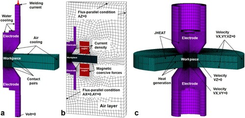
Figure (b) shows the electro-magnetic field model. The current density is applied to the electrodes and workpieces as loading conditions. The magnetic coercive forces of the upper and lower permanent magnets are set as 955000 A/m and −955000 A/m, respectively. The parallel boundary condition AZ = 0 is applied to the air layer. The boundary conditions AX = 0 and AY = 0 are applied to the symmetric axis for the central axisymmetric magnetic field.
Because of the multidirectional fluid flow in the MA-RSW process, a 3D 360-degree thermal-flow field model is needed, as shown in Figure (c). The loading conditions consist of Joule heating by the workpiece and heat flux by contact pairs. The boundary conditions consist of zero velocity constraints on the outer surface of the workpiece, radial zero velocity constraints on the axis of this model, and axial zero velocity constraints on the workpiece-workpiece interface.
2.3. Material properties
The RSW process is a typical transient multiphysical field coupling process. To improve the accuracy of the simulation results, the material properties of the workpiece are defined as temperature-dependent properties. The properties of the Al sheet and copper electrode caps, such as electrical resistivity, thermal conductivity, and specific heat are exhibited in Figure and Table (Deng et al., Citation2020; Riahi & Nazari, Citation2011; Wan et al., Citation2016; Wang et al., Citation2015).
Figure 2. Temperature-dependent properties of the AA6061-T6 sheet and Cr-Zr-Cu alloy electrode. (a) Electrical resistivity and (b) thermal conductivity.
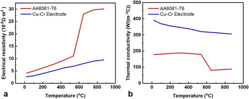
Table 1. Specific heat of AA6061-T6 and Cr-Zr-Cu electrode.
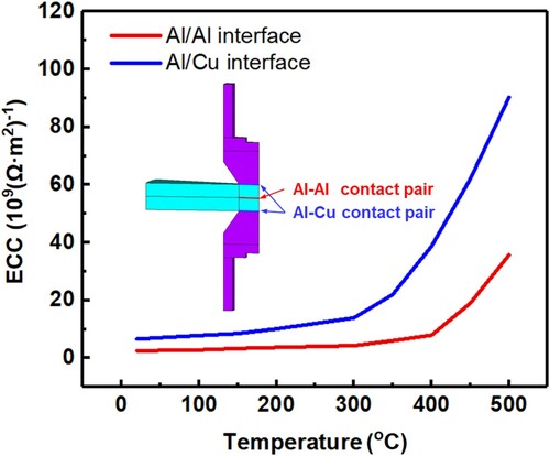
Electric contact conductance (ECC) and thermal contact conductance (TCC) are also essential for the calculations in the RSW process. According to the published data (Wang et al., Citation2015; Tuchtfeld et al., Citation2019), the ECC for Cu/Al and Al/Al interfaces can be calculated and are given in Figure . In addition, the effect of TCC on nugget growth can be ignored since there is no structure field in this model and the electrode tip and workpiece are in an as-received condition. The TCC of Cu/Al and Al/Al contact surfaces is set to a value of .
Figure 3. Electric contact conductance on Al/Al and Al/Cu contact interfaces as a function of temperature.
In the analysis of thermo-flow field, both the liquid phase and the solid phase exist in the workpiece during the MA-RSW process. To solve the changing liquid–solid interface, this paper introduces an artificial viscosity method to treat entire workpiece as a fluid. As shown in Table (Jeng and Chen, Citation1997; Noshadi et al., Citation1998), when the temperature of the workpiece is lower than its melting point, a very high viscosity (109 kg/(m·s)) is assigned to ensure that the solid metal does not flow at that time. When the temperature reaches or exceeds the melting point of the workpiece, the true viscosity (1.3810−3 kg/(m·s)) is given to ensure the flow and heat transfer of liquid metal under the action of electromagnetic force. Moreover, the EMF is produced by a pair of ring-shaped Nd-Fe-B permanent magnets with a relative permeability of
=1.05. The detailed parameters are listed in Table .
Table 2. Artificial viscosity of workpieces.
Table 3. Parameters of the permanent magnet.
2.4. Solution procedure
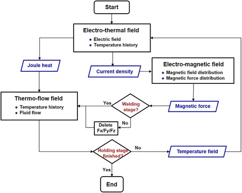
The solution procedures of RSW and MA-RSW processes are given in Figure . Sequential coupling is conducted at each time increment. At the beginning of the welding stage, the electro-thermal field is first calculated to obtain the initial current density and temperature distribution in the workpieces. Then, the current density and temperature distribution are introduced into the electro-magnetic field model and thermo-flow field model as loads, respectively. Then, the electromagnetic force distribution under the action of the EMF and the IMF is calculated in the electro-magnetic field model and output to the thermo-flow field model. After that, the new temperature distribution is calculated in the thermo-flow field under loads of Joule heat and electromagnetic force and output back to the electro-thermal field model for the next loop.
Figure 4. Solution procedure of MA-RSW multiphysics behaviors.
3. Experimental procedures
In this study, two identical 3.0-mm thick AA6061-T6 sheets were used as the research material for the numerical model and experimental materials. The workpieces were sheared into 38 ×130 mm. The oxide film of the aluminum alloy was removed by mechanical grinding. As shown in Figure (a), a medium frequency direct current (MFDC) welding machine integrated with a FANUC R-2000i robot was used to weld the workpieces. A pair of C15000 copper alloy electrodes was adopted, and the tip diameter was 12 mm.
Figure 5. Experimental system. (a) RSW machine and (b) MA-RSW apparatus.
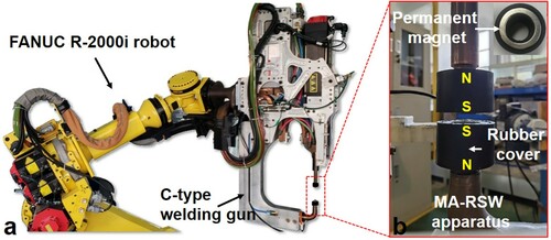
The MA-RSW apparatus consists of a pair of mutually exclusive circular permanent magnets with rubber covers, as shown in Figure (b). The detailed parameters of the permanent magnet are listed in Table . The distance between the permanent magnet and workpiece is kept at 1 mm to prevent the demagnetization effect of high temperature on the permanent magnet. According to the characteristics of the aluminum workpiece, the optimized welding parameters used in the numerical calculation and model validation were determined, as shown in Figure .
Figure 6. Welding schedule of RSW and MA-RSW process.
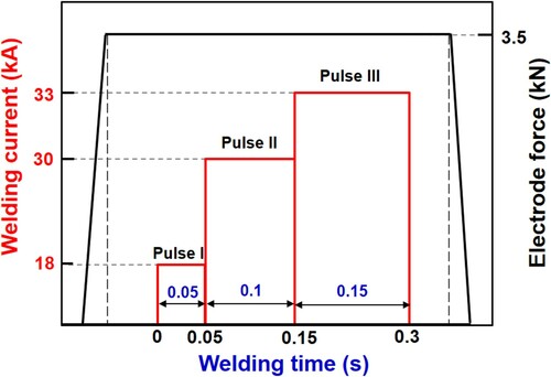
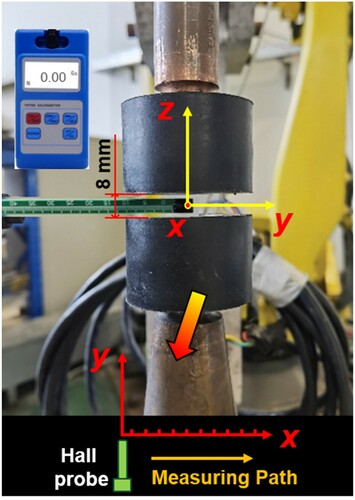
Figure shows the measurement process of the magnitude of the EMF in the nugget region. The distance between the upper and lower permanent magnets is fixed at 8 mm, which is consistent with the experimental process and simulation model. The Hall probe of the Gauss meter is placed vertically on the central axis to measure the radial magnetic field component, and then measured along the x-axis.
Figure 7. The measurement process of the radial magnetic field.
In the preparation of metallographic samples, the cross-sectioned samples were first mounted, polished with silicon papers and etched with Keller (95 ml H2O + 2.5 ml HNO3 + 1.5 ml Hcl +1.0 ml HF). The macro- and micro structures of weld nuggets were photographed by Leica optical microscope systems. The electron backscattered diffraction (EBSD) test was carried out with a Tescan Mira3 scanning electron microscope.
4. Model validation
4.1. Mesh independence verification
To eliminate the effect of the mesh number on the accuracy of simulated results, Table exhibits the mesh independence verification of the RSW and MA-RSW models with five schemes of different mesh numbers. When the mesh number exceeds mesh scheme B, the change of maximum temperature in traditional RSW and MA-RSW nuggets at 0.3 s is less than 1%. Therefore, on the premise of both accuracy and computational efficiency, mesh scheme B is selected as the computational grid.
Table 4. Mesh independence verification of numerical model.
4.2. Verification of the intensity of external magnetic field
To ensure the accuracy of electro-magnetic field, this study compared the intensity of the EMF on the workpiece/workpiece contact surface between the simulated and experimental results, as shown in Figure . The radial magnetic field intensity of the simulated result is extracted from the same measuring path of the experimental results.
Figure 8. Comparison of radial magnetic flux density between experimental and simulated results.
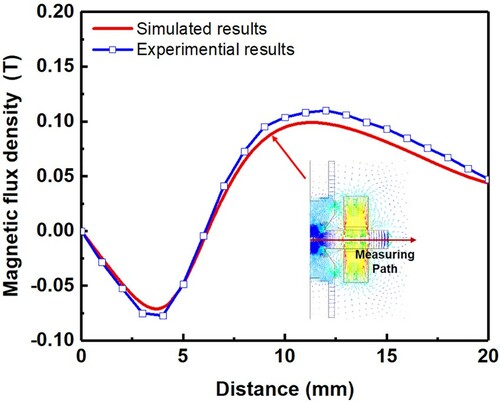
The calculated result is in accordance with the changing trend of the measured result. The simulation error of each measuring point is relatively stable. Since the probe of the Gauss meter calculates the magnetic field by measuring the magnetic flux on a small square area rather than a point, there is a 2% systematic error in the measurement.
4.3. Verification of nugget morphology and size
Figure and Table show the experimental results and calculation results of the RSW and MA-RSW nuggets. The calculated results of nugget morphology and size are basically consistent with the experimental results. The average simulation error is less than 10%. There are two main reasons for the errors between the calculated results and the experimental results: 1) This model mainly focuses on MHD behaviors in the RSW and MA-RSW processes, ignoring the influence of workpiece indentation and deformation on the nugget formation process, which results in errors in nugget thickness; 2) In this model, the idealized artificial viscosity method is used in thermo-flow field. The analysis of viscoelastic flow behavior in the mixed zone of solid and liquid phases during the melting process is insufficient, which affects the calculation results of the thermo-flow field.
Figure 9. Comparison between simulated and experimental results of nugget morphology. (a) RSW-0.25 s, (b) RSW-0.3 s, (a1) MA-RSW-0.25 s and (b1) MA-RSW-0.3 s.
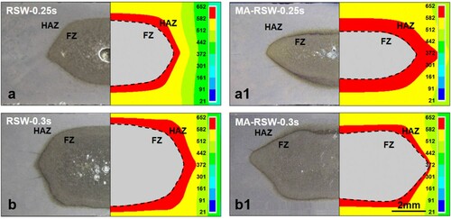
Table 5. Comparison between the simulated and experimental nugget size.
5. Results and discussion
5.1. Distribution of the electromagnetic force under the effect of a magnetic field
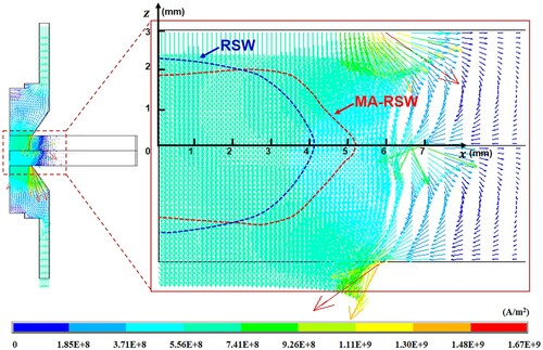
To reveal the influence mechanism of an EMF on the flow pattern of liquid nuggets, this paper compares the magnetic field and magnetic force distribution during RSW and MA-RSW. As shown in Figure (a), in the RSW process the IMF is produced by a vertical welding current that exists in the region of the nugget (refer to Figure ). It is distributed uniformly along the circumferential direction on the horizontal plane of A-A. However, in the MA-RSW process, the magnetic field in the nugget consists of two components, as shown in Figure (b). The first is the circumferential IMF produced by the welding current. The second is the external radial magnetic field generated by the permanent magnets. The intensity of the magnetic field during RSW, and MA-RSW first increases and then decreases in a radial direction from the symmetrical axis to the workpiece edge. The intensity of the IMF reaches a maximum at the brim of the nugget because the current density is the highest at the edge of the electrode (refer to Figure ). However, in the notch region, the air gap makes it difficult for a current path to form, and consequently, the current density and the IMF intensity decrease rapidly.
Figure 10. Distribution of the magnetic field in the welding region (welding time, 0.3 s). (a) RSW and (b) MA-RSW.
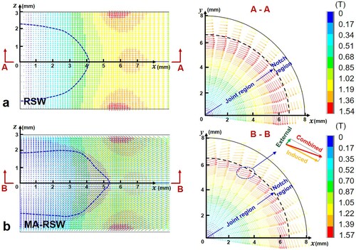
Figure 11. Distribution of the current density in the RSW, and MA-RSW processes at 0.3s.
On the other hand, although an EMF is introduced in MA-RSW process, the maximum intensity of the MA-RSW combined magnetic field is only 0.03 T higher than that of RSW. This is because the intensity of an EMF is far less than that of an IMF. Therefore, the direction of the MA-RSW magnetic field rotates from the tangential direction of the IMF and slightly in the radial direction of the EMF (see in sectional drawing B-B of Figure (b)).
As shown in Figure (a), according to Fleming’s left-handed rule, the electromagnetic force generated by the IMF only exists in the x-z planes in the RSW process. The distribution of the in-plane induced electromagnetic force points to the central axis and increases gradually from the Al/Al contact surface to the Al/Cu contact surface, as illustrated in sectional drawing A-A of Figure (a).
Figure 12. Distribution of the electromagnetic force within the welding region. (a) RSW, and (b) MA-RSW.
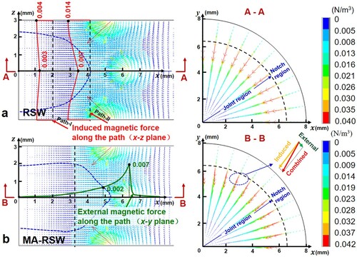
As shown in Figure (b), both the in-plane (x-z plane) induced magnetic force and the out-of-plane (x-y plane) external magnetic force exist in the welding region of the MA-RSW process. The direction of the combined electromagnetic force in the nugget of an MA-RSW basically points to the central axis of the electrode, but the vector direction rotates slightly in the circumferential direction, as shown in sectional drawing B-B of Figure (b). In addition, the magnitude of the external electromagnetic force decreases gradually from approximately 0.002 N/m3 at the nugget edge to 0 N/m3 at the nugget center, which is much lower than that of the induced electromagnetic force in the nugget region. However, this small change produces a considerable impact on the flow pattern inside the nugget.
5.2. Fluid flow pattern and evolution in the weld nugget
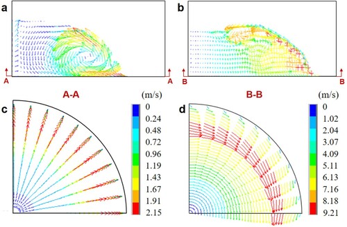
The flow pattern of the liquid metal plays an important role in the growth process of nuggets. During the welding stage of the RSW process, as shown in Figure (a), the induced magnetic force gradually strengthens from faying surface to nugget brim along the thickest section of the nugget. This nonuniform magnetic force gradient results in the liquid metal at the edge of the nugget brim having a stronger force, which causes the liquid nugget to form a counter-clockwise flow pattern, as illustrated in Figure (a1). When the nugget increases, as shown in Figure (b1) and (c1), rotation cores in each quarter gradually move from the center of the nugget to the edge because the rate of growth of the nugget in the direction of its thickness is far slower than that in the direction of its diameter. In addition, the molten metal exhibits in-plane flow solely in the radial plane, and there is no circumferential velocity component, as shown in Figure .
Figure 13. Cross-sectioned view of the flow pattern in the nugget at different times during the welding process. (a1)-(f1) RSW and (a2)-(f2) MA-RSW.
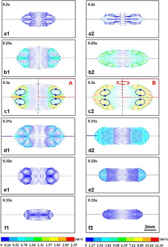
Figure 14. Details of flow pattern in the quarter nugget. (a) corresponds to the location A for RSW nugget, as marked in Figure (c1). (b) corresponds to the location B for MA-RSW nugget, as marked in Figure (c2). (c) Faying surface of the RSW nugget. (d) Faying surface of the MA-RSW nugget.
In addition, the maximum flow velocity of the liquid nugget in the aluminum alloy RSW process is 2.35 m/s, which is approximately 5 times faster than the 0.48 m/s of the liquid nugget in mild steel RSW process calculated by Li et al. (Citation2011). This change is mainly attributed to two factors. First, the welding current of aluminum alloy RSW is usually 2∼6 times higher than that of the steel RSW process. Thus, the IMF and electromagnetic force is significantly enhanced. Second, the viscosity of the AA6061 aluminum alloy is 0.00138 kg/(m·s), which is much lower than the 0.006 kg/(m·s) of mild steel. The loss caused by the internal friction of fluid flow is significantly reduced.
In the MA-RSW process, the molten metal has not only a radial velocity component but also a circumferential velocity component, as shown in Figure . At the beginning of the MA-RSW process, the circumferential flow velocity is relatively low. The molten metal in the weld nugget is mainly shown as in-plane flow as in the RSW process, as shown in Figure (a2). During the middle and late welding stages, as illustrated in Figure (b2) and (c2), the circumferential stirring effect of the external magnetic force increases gradually with the growth of the nugget. Thus, the circumferential flow gradually replaces the in-plane flow as the dominant flow pattern. As shown in Figure , the maximum compound flow velocity reaches 11.43 m/s, which is more than five times faster than that of RSW. Furthermore, under the action of the out-of-plane high-speed flow in the MA-RSW nugget, the in-plane flow velocity of MA-RSW is significantly enhanced, and is approximately twice the velocity of RSW. This phenomenon mainly occurs because the four fluids in the four quadrants of the RSW process undergo in-plane flow, which cancels each other out near the symmetric axis region. However, the molten metal of the MA-RSW nugget accelerates continuously in the circumferential direction under the continuous stirring effect of the electromagnetic force without the canceling out effect.
Figure 15. Evolution of the maximum flow velocity in the RSW, and MA-RSW processes.

Figure (d1)-(f1) shows the holding stage of the RSW process. The molten metal still undergoes an in-plane flow under the action of inertial force. While the flow pattern is more complex, and multiple rotation cores are formed. The flow velocity drops sharply below 0.01 m/s, as shown in Figure . On the other hand, in the holding stage of MA-RSW, as shown in Figure (d2)-(f2), molten metal continues to undergo high-speed circumferential flow due to the inertia effect. This high-speed flow transforms the solidification mode of the MA-RSW nugget, which will be discussed in the following sections.
5.3. Distribution of the temperature field and evolution in the weld nugget
The stirring effect of the EMF changes the flow pattern in liquid nugget, which causes the temperature field of the MA-RSW weld to be significantly different from that of the RSW weld. Previous numerical models did not include the MHD behaviors of the RSW process. This section compares the simulation results of three kinds of models, i.e. the traditional RSW model (only the electro-thermal field is considered), the MHD-RSW model (four-field coupling), and the MA-RSW model (four-field coupling), to reveal the MHD behaviors during the RSW and MA-RSW processes.
Figures and show the evolution of the temperature field and the temperature history of four special points in a weld nugget calculated using the three types of numerical models, respectively. To reveal the temperature gradient of the liquid nugget, the unmelted zone below the melting temperature of 652 °C is colored gray. Before melting, as shown in Figure (a), the temperature of the workpiece increases rapidly under the action of contact and bulk resistance. The temperature rises slowly when it reaches the phase transformation region. The three types of RSW processes have the same temperature history in this period without the effect of fluid flow.
Figure 16. Evolution of the temperature field in weld nuggets. (a1)-(f1) Traditional RSW model, (a2)-(f2) MHD-RSW model, and (a3)-(f3) MA-RSW model.
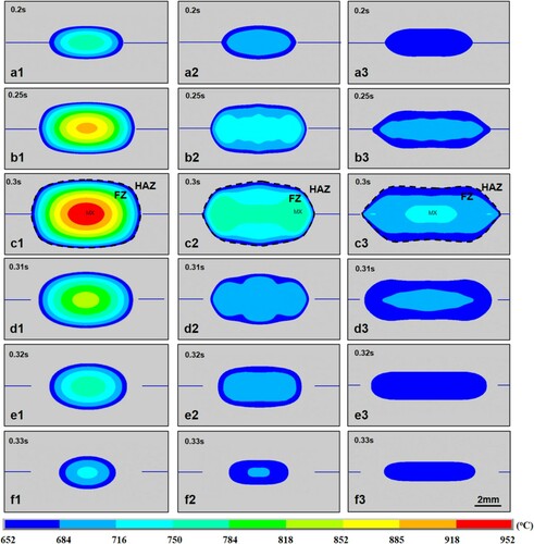
Figure 17. Temperature history of different positions in a nugget as described by the traditional RSW, MHD-RSW, and MA-RSW models. (a) P1, (b) P2, (c) P3, and (d) P4.
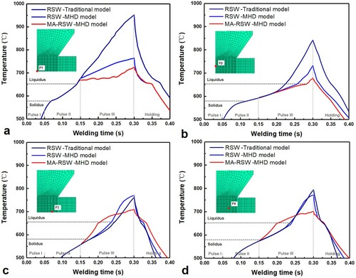
When the temperature exceeds the liquidus, as shown in Figure (a1)-(c1), the traditional RSW model predicts that the temperature of the nugget will continue to rise rapidly until the last welding moment. In addition, the high-temperature region is concentrated at the center of the nugget, which is consistent with most of the existing research results. In contrast, when the IMF and flow field are considered in the MHD-RSW model, as shown in Figure (a2)-(c2), the high-temperature region in the nugget gradually shifts from the center to the edge under the effect of the in-plane flow (refer to Figure (a1)-(c1)). Due to the convection effect of high-temperature and low-temperature metals in the nugget, the maximum temperature calculated by the MHD-RSW model is reduced from 952 as calculated by the traditional RSW model, to 774
.
During the MA-RSW process, the temperature distribution is affected by both the in-plane flow and out-of-plane high-speed flow. Figure (c) and (d) shows the beginning of nugget growth, the rate at which the temperature increases at points P3 and P4 in MA-RSW process is much higher than that of the MHD-RSW process. This means that the introduction of the EMF can effectively improve the growth rate of the nugget diameter. Furthermore, as shown in Figure (a3)-(c3), the compound high-speed flow further decreases the maximum temperature and temperature gradient in the weld nugget. The maximum temperature is reduced to 725, and the energy efficiency is further improved.
During the holding stage, as shown in Figure (c1)-(f1), the molten metal solidifies rapidly from the nugget edge to the center because of the effect of water and air cooling. The high-temperature region is constant in the nugget center. However, in the MHD-RSW process illustrated in Figure (c2)-(f2), the high-temperature region contracts from both sides of the nugget edge to the center along the faying surface with a rapid decrease in flow velocity (refer to Figure ). As shown in Figure (c3)-(f3), during the holding stage of MA-RSW process, the inertial flow maintains a high flow rate after the welding current has been disconnected (refer to Figure (c2)-(f2)). Thus, the temperature gradient and solidification rate of the nugget change significantly during solidification, and its influence on the microstructure will be discussed in the next section.
5.4. Influencing mechanism of the magnetic field on weld macro- and microstructures
Figure shows the variation in the nugget diameter and thickness associated with the welding time calculated using the three types of models. The nugget sizes at 0.25 and 0.3 s have been verified in Section 4.2. With the effect of the EMF, the nugget diameter during an MA-RSW weld is significantly increased, and is approximately 19.8% and 25.5% higher than that of the RSW welds at 0.25 and 0.3 s, respectively. In addition, the RSW welds are approximately elliptical in shape, while both ends of an MA-RSW nugget are sharper and thinner than those of the RSW welds.
Figure 18. Change in the size of the nugget at different times during the welding process. (a) Nugget diameter, and (b) nugget thickness.
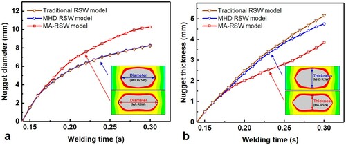
The main reasons for the above phenomenon should be attributed to the high-speed combined flow. On the one hand, under the influence of the enhanced in-plane flow, the liquid metal continues to flow and transfers the heat from the nugget center to the edge. On the other hand, under the action of the out-of-plane flow, the high velocity flow scours the nugget brim, which enhances the heat transfer and greatly increases the nugget diameter. In addition, because the total heat input does not change during the MA-RSW process, the heat transferred from the center to the edge of the nugget would slow down its growth rate in the thickness direction. A decrease in the thickness of the nugget is beneficial to avoid an excessive penetration rate and delay electrode pitting.
Furthermore, the microstructure of the MA-RSW nugget is also different from that of the RSW nugget. Figure (a) and (d) shows the notch region of the RSW and MA-RSW nuggets. The columnar grain zone (CGZ) in the MA-RSW nugget is wider compared with the RSW nugget. At the end of welding stage, the maximum velocities in the RSW and MA-RSW nuggets are 2.35 and 11.43 m/s, respectively. Thus, the molten metal can keep a high-speed inertial flow at the beginning of solidification (refer to Figure ), which reduces the solidification rate (refer to Figure (c3)-(d3)) along the solidification front at the nugget notch region compared with the RSW process. The slower solidification rate promotes the growth of the columnar grains and leads to a wider CGZ of the MA-RSW nuggets based on the study of the columnar to equiaxed transition (CET) proposed by Hunt (Citation1984).
Figure 19. Microstructures of weld nuggets. (a), (b) and (c) Traditional RSW. (d), (e) and (f) MA-RSW.
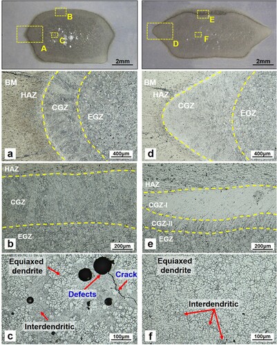
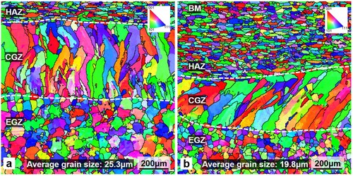
Figure (b) and (e) shows the upper region of RSW and MA-RSW nuggets, which is close to the electrode. The direction of growth of the CGZ in the RSW nugget is perpendicular to the fusion line. However, the direction of growth of the CGZ in MA-RSW nugget deflects approximately 45 degrees because of the deflection of the heat-extraction direction due to the circumferential inertial flow. Furthermore, a double-layered grain structure with different colors is observed at the upper edge of the MA-RSW nugget. To further confirm the difference between them, the EBSD inverse pole figure map of this area is plotted in Figure . The results show that both CGZ-I and CGZ-II are columnar grains and there is no obvious structural difference between them. Huang et al. (Citation2020) and Li et al. (Citation2016) reported a similar phenomenon. The main reason for this could be the effect of segregation. Under the effect of forced water cooling of the electrode, both the nuggets of RSW and MA-RSW cooled rapidly. Due to the lower temperature of the upper region in the MA-RSW nugget (Figure (d3)) and forced water-cooling effect, the solidification rate at the upper region of the MA-RSW nugget is higher compared with the RSW nugget. Therefore, as shown in Figure (e), the secondary phase has no time to precipitate and results in the formation of high-contrast CGZ-I. Furthermore, the solidification rate of the nugget gradually decreases as it gets closer to the center of the nugget due to the effect of high-speed inertial flow (refer to Figure ). Thus, the synergistic effects of the concentration of the high solute elements and low solidification rate lead to the formation of low-contrast CGZ-II.
Figure 20. EBSD inverse pole figure map of the upper region of two types of nuggets. (a) The RSW nugget corresponding to Figure (b). (b) The MA-RSW nugget corresponding to Figure (e).
In addition, the relatively larger temperature gradient (Figure (e2)) and higher cooling rate (Figure ) result in insufficient flow and heat transfer inside the nugget, which inhibits heterogeneous growth and results in a high volume fraction of interdendritic regions (Tian et al., Citation2019), as shown in Figure (c). The liquid metal solidifies gradually from the edge of the nugget to its center. This is a typical sequential solidification mode and is prone to produce shrinkage defects in the center of the nugget. In contrast, the high-speed flow in the MA-RSW nugget is conducive to breaking the dendrites during the solidification process. Furthermore, due to the relatively small temperature gradient (Figure (e3)) and low cooling rate (Figure (a)) in the center of the MA-RSW nugget, dendrites with smaller arm spacing could remelt and disappear (Terzi et al., Citation2010), and the solidification mode is transformed from the sequential mode to the simultaneous mode. As a result, the shrinkage defects and the volume fraction of interdendritic regions are greatly reduced, as shown in Figure (f). The average grain size of the EGZ of the MA-RSW is 19.8 μm, which is 21.7% finer than that of the RSW, as shown in Figure (b).
6. Conclusions
In this paper, an MHD model coupling of the electrical, thermal, magnetic, and fluid fields was established. The magnetic field, fluid flow pattern, temperature evolution, and weld macro- and microstructures in the RSW and MA-RSW processes of aluminum alloys were studied. The following conclusions can be drawn:
The flow pattern and the temperature field distribution of the liquid nugget in the aluminum alloy RSW process are similar to those of the steel RSW process. However, due to the stronger induced electromagnetic force generated by the larger welding current, the maximum flow velocity of the liquid nugget in the aluminum alloy RSW process by the induced magnetic field is increased from approximately 0.48 m/s for mild steel (calculated by Li et al. (Citation2011)) to approximately 2.35 m/s.
The radially induced electromagnetic force in the RSW process can only produce a single in-plane flow. In comparison, the circumferential electromagnetic force generated by the external magnetic field in the MA-RSW process can transform the in-plane flow into a three-dimensional combined flow. This change improves the maximum flow velocity to five times that of the RSW process, reaching 11.43 m/s.
The high-temperature zone is concentrated at both sides of the nugget in the RSW process, and the temperature gradient is relatively large. Under the effect of the combined flow in MA-RSW, the temperature gradient inside the nugget decreases significantly, and the maximum temperature drops from 774°C for RSW to 725°C.
The increase rate of the nugget diameter is mainly in the range of 6%∼15% in steels MA-RSW as reported by Shen et al. (Citation2011) and Qi et al. (Citation2020). In the aluminum alloy MA-RSW process, however, due to the higher flow velocity and heat transfer efficiency, the increase rate reaches 25.5%.
During the MA-RSW solidification process, the solidification mode of the nugget center transforms from sequential mode to simultaneous mode due to the small temperature gradient. Compared with the RSW nugget, the shrinkage defects inside the MA-RSW nuggets are greatly reduced, and the average grain size of the EGZ is refined by 21.7%.
This numerical model provides an effective method to reveal the influencing mechanism of the EMF on the flow pattern and microstructure of welds. However, this model also has some limitations that need to be overcome. For instance, this model ignores the influence of the structural field, which has a certain influence on the accuracy of the heat generation and nugget size. In the future, this model will consider the structure field to realize five-field coupling. Furthermore, this model could be coupled with a computational grain growth model to predict the evolution of grain morphology and orientation.
Disclosure statement
The authors declare that they have no known competing financial interests or personal relationships that could have appeared to influence the work reported in this paper.
Additional information
Funding
References
- Abadi, A. M. E., Sadi, M., Farzaneh-Gord, M., Ahmadi, M. H., & Chau, K. W. (2020). A numerical and experimental study on the energy efficiency of a regenerative heat and mass exchanger utilizing the counter-flow maisotsenko cycle. Engineering Applications of Computational Fluid Mechanics, 14(1), 1–12. https://doi.org/https://doi.org/10.1080/19942060.2019.1617193
- Bi, J., Song, J., Wei, Q., Zhang, Y., Li, Y., & Luo, Z. (2016). Characteristics of shunting in resistance spot welding for dissimilar unequal-thickness aluminum alloys under large thickness ratio. Materials & Design, 101, 226–235. https://doi.org/https://doi.org/10.1016/j.matdes.2016.04.023
- Deng, L., Li, Y. B., Cai, W., Haselhuhn, A. S., & Carlson, B. E. (2020). Simulating thermoelectric effect and its impact on weld nugget asymmetric growth in aluminum resistance spot welding. Journal of Manufacturing Science and Engineering, 142(9), 091001. https://doi.org/https://doi.org/10.1115/1.4047243
- Florea, R. S., Hubbard, C. R., Solanki, K., Bammann, D. J., Whittington, W. R., & Marin, E. B. (2012). Quantifying residual stresses in resistance spot welding of 6061-T6 aluminum alloy sheets via neutron diffraction measurements. Journal of Materials Processing Technology, 212(11), 2358–2370. https://doi.org/https://doi.org/10.1016/j.jmatprotec.2012.06.024
- Granados-Ortiz, F. J., Leon-Prieto, L., & Ortega-Casanova, J. (2021). Computational study of the application of al 2 o 3 nanoparticles to forced convection of high-reynolds swirling jets for engineering cooling processes. Engineering Applications of Computational Fluid Mechanics, 15(1), 1–22. https://doi.org/https://doi.org/10.1080/19942060.2020.1845805
- Huang, M., Zhang, Q., Qi, L., Deng, L., & Li, Y. (2020). Effect of external magnetic field on resistance spot welding of aluminum alloy AA6061-T6. Journal of Manufacturing Processes, 50, 456–466. https://doi.org/https://doi.org/10.1016/j.jmapro.2020.01.005
- Hunt, J. D. (1984). Steady state columnar and equiaxed growth of dendrites and eutectic. Materials Science and Engineering, 65(1), 75–83. https://doi.org/https://doi.org/10.1016/0025-5416(84)90201-5
- Jeng, S., & Chen, S. (1997). The solidification characteristics of 6061 and A356 aluminum alloys and their ceramic particle-reinforced composites. Acta Materialia, 45(12), 4887–4899. https://doi.org/https://doi.org/10.1016/S1359-6454(97)00189-4
- Kang, J., Chen, Y., Sigler, D. R., Carlson, B. E., & Wilkinson, D. S. (2016). Effect of adhesive on fatigue property of Aural2 to AA5754 dissimilar aluminum alloy resistance spot welds. Engineering Failure Analysis, 69, 57–65. https://doi.org/https://doi.org/10.1016/j.engfailanal.2016.01.009
- Khan, J. A., Xu, L., Chao, Y., & Broach, K. (2000). Numerical simulation of resistance spot welding process. Numerical Heat Transfer Part A-Applications, 37(5), 425–446. https://doi.org/https://doi.org/10.1080/104077800274145
- Li, Y. B., David, S. A., Lim, Y. C., & Feng, Z. (2016). Microstructures of magnetically assisted dual-phase steel resistance spot welds. Science and Technology of Welding and Joining, 21(7), 555–563. https://doi.org/https://doi.org/10.1080/13621718.2016.1141493
- Li, Y. B., Lin, Z. Q., Hu, S. J., & Chen, G. L. (2007). Numerical analysis of magnetic fluid dynamics behaviors during resistance spot welding. Journal of Applied Physics, 101(5), 053506. https://doi.org/https://doi.org/10.1063/1.2472279
- Li, Y. B., Lin, Z. Q., Shen, Q., & Lai, X. M. (2011). Numerical analysis of transport phenomena in resistance spot welding process. Journal of Manufacturing Science and Engineering-Transactions of the ASME, 133(3), 031019. https://doi.org/https://doi.org/10.1115/1.4004319
- Li, Y., Zhang, Y., Bi, J., & Luo, Z. (2015). Impact of electromagnetic stirring upon weld quality of Al/Ti dissimilar materials resistance spot welding. Materials & Design, 83, 577–586. https://doi.org/https://doi.org/10.1016/j.matdes.2015.06.042
- Li, Y. B., Zhang, Q. X., Qi, L., & David, S. A. (2018). Improving austenitic stainless steel resistance spot weld quality using external magnetic field. Science and Technology of Welding and Joining, 23(7), 619–627. https://doi.org/https://doi.org/10.1080/13621718.2018.1443997
- Moshayedi, H., & Sattarifar, I. (2012). Numerical and experimental study of nugget size growth in resistance spot welding of austenitic stainless steels. Journal of Materials Processing Technology, 212(2), 347–354. https://doi.org/https://doi.org/10.1016/j.jmatprotec.2011.09.004
- Noshadi, V., Schneider, W., & Kuznetsov, A. V.. (1998). Internal flow and shell solidification in horizontal continuous casting processes. In Proceedings of the eighth International conference on modeling of casting, Welding, and Advanced Solidification Processes VIII, San Diego, CA, June 7-12, 655–662.
- Qi, L., Li, F. Z., Chen, R. M., Zhang, Q. X., & Li, Y. B. (2020). Improve resistance spot weld quality of advanced high strength steels using bilateral external magnetic field. Journal of Manufacturing Processes, 52, 270–280. https://doi.org/https://doi.org/10.1016/j.jmapro.2020.02.030
- Ramezanizadeh, M., Alhuyi Nazari, M., Ahmadi, M. H., & Chau, K. W. (2019). Experimental and numerical analysis of a nanofluidic thermosyphon heat exchanger. Engineering Applications of Computational Fluid Mechanics, 13(1), 40–47. https://doi.org/https://doi.org/10.1080/19942060.2018.1518272
- Riahi, M., & Nazari, H. (2011). Analysis of transient temperature and residual thermal stresses in friction stir welding of aluminum alloy 6061-T6 via numerical simulation. The International Journal of Advanced Manufacturing Technology, 55(1–4), 143–152. https://doi.org/https://doi.org/10.1007/s00170-010-3038-z
- Shen, Q., Li, Y. B., Lin, Z. Q., & Chen, G. L. (2011). Effect of external constant magnetic field on weld nugget of resistance spot welded dual-phase steel DP590. IEEE Transactions on Magnetics, 47(10), 4116–4119. https://doi.org/https://doi.org/10.1109/TMAG.2011.2157316
- Terzi, S., Salvo, L., Suery, M., Dahle, A. K., & Boller, E. (2010). Coarsening mechanisms in a dendritic Al–10% Cu alloy. Acta Materialia, 58(1), 20–30. https://doi.org/https://doi.org/10.1016/j.actamat.2009.08.052
- Tian, Q. W., Zhang, G. J., Yin, K. X., Wang, W. W., Cheng, W. L., & Wang, Y. N. (2019). The strengthening effects of relatively lightweight AlCoCrFeNi high entropy alloy. Materials Characterization, 151, 302–309. https://doi.org/https://doi.org/10.1016/j.matchar.2019.03.006
- Tuchtfeld, M., Heilmann, S., Fussel, U., & Juttner, S. (2019). Comparing the effect of electrode geometry on resistance spot welding of aluminum alloys between experimental results and numerical simulation. Welding in the World, 63(2), 527–540. https://doi.org/https://doi.org/10.1007/s40194-018-00683-z
- Wan, Z., Wang, H., Wang, M., Carlson, B. E., & Sigler, D. R. (2016). Numerical simulation of resistance spot welding of Al to zinc-coated steel with improved representation of contact interactions. International Journal of Heat and Mass Transfer, 101, 749–763. https://doi.org/https://doi.org/10.1016/j.ijheatmasstransfer.2016.05.023
- Wang, Y., Tao, W., & Yang, S. (2019). A method for improving joint strength of resistance spot welds of aa 5182-o aluminum alloy. Journal of Manufacturing Processes, 45, 661–669. https://doi.org/https://doi.org/10.1016/j.jmapro.2019.07.024
- Wang, J., Wang, H., Lu, F., Carlson, B. E., & Sigler, D. R. (2015). Analysis of Al-steel resistance spot welding process by developing a fully coupled multi-physics simulation model. International Journal of Heat and Mass Transfer, 89, 1061–1072. https://doi.org/https://doi.org/10.1016/j.ijheatmasstransfer.2015.05.086
- Wei, P. S., Wang, S. C., & Lin, M. S. (1996). Transport Phenomena during resistance spot welding. Journal of Heat Transfer-Transactions of the ASME, 118(3), 762–773. https://doi.org/https://doi.org/10.1115/1.2822697
- Wei, P. S., & Wu, T. H. (2012). Electrical contact resistance effect on resistance spot welding. International Journal of Heat and Mass Transfer, 55(11–12), 3316–3324. https://doi.org/https://doi.org/10.1016/j.ijheatmasstransfer.2012.01.040
- Wei, P. S., & Yeh, F. B. (1991). Factors affecting nugget growth with mushy-zone phase change During Resistance spot welding. Journal of Heat Transfer-Transactions of the ASME, 113(3), 643–649. https://doi.org/https://doi.org/10.1115/1.2910613
- Yao, Q., Luo, Z., Li, Y., Yan, F., & Duan, R. (2014). Effect of electromagnetic stirring on the microstructures and mechanical properties of magnesium alloy resistance spot weld. Materials & Design, 63, 200–207. https://doi.org/https://doi.org/10.1016/j.matdes.2014.06.004