
 ?Mathematical formulae have been encoded as MathML and are displayed in this HTML version using MathJax in order to improve their display. Uncheck the box to turn MathJax off. This feature requires Javascript. Click on a formula to zoom.
Abstract
The liquid rocket propellant burns inadequately in the combustion chamber; therefore, the exhaust gas reacts with oxygen and the heat that was generated, which in turn affects the thermal environment. By using finite-rate chemical kinetics and discrete ordinates method, the calculation model for the four-engine rocket exhaust flowfield is established, and numerically investigates the afterburning effect on the thermal environment of the engine exhaust plume under different altitudes. The results show that the afterburning reactions have little influence on the Mach number exhaust flow, and the difference between the peak temperatures of reacting and non-reacting flows is less than 5%. However, a significant increase in temperature of the mixing layer can be found, and the afterburning effect on the thermal environment reduces with increases in the flight altitude. At the same altitude, the temperature increment of the reacting flow in the far-field region is higher than that of the near-field region. Moreover, as the flight altitude increases from 15 to 35 km, the increase of the rocket base heat flux caused by the afterburning can vary from 9.4% to 2.7%. The results provide a theoretical basis for the designing of the thermal protection systems of multi-engine rockets.
Nomenclature
| A | = | frequency factor |
| E | = | energy density |
| EA | = | activation energy |
| gl | = | Gibbs free energy of species l. |
| K | = | thermal conductivity coefficient |
| Kfr | = | forward reaction rate |
| Ml | = | chemical symbol |
| Pk | = | rate of turbulence energy |
| p | = | normal stress of fluid |
| R0 | = | constant of universal gas |
| T | = | temperature |
| Tt | = | realizable estimate of the turbulence time scale |
| Wl | = | molecular weight of species l |
| ρ | = | mass density |
| τ | = | shear stress tensor |
| μ | = | fluid viscosity coefficient |
| ωlr | = | rate of production |
| RANS | = | Reynolds-averaged Navier–Stokes |
1. Introduction
In rocket engines, the combustion reactions of the propellant produce enormous amounts of energy, which generates a gas flow along an established direction with the help of the Laval nozzle. The supersonic exhaust gas flow can produce thrust for rocket launch (Crocco et al., Citation1964; Whitefield et al., Citation2000; Zhou, Wang, et al., Citation2020). The exhaust gas from the Laval nozzles, which has a high pressure and temperature, expands rapidly in the external environment and forms reverse plume, and then, it heats the rocket base. Compared with single-engine rockets, the thermal environment of multiple-engine rockets is more complex due to the interaction of multiple-plumes (Xiong et al., Citation2020). Due to the gasdynamic continuously heating over the launch vehicle by exhaust gas, the high-temperature region occurs at the rocket base and may cause significant erosion and damage (Mehta, Citation1981). In order to ensure the security of the rocket flight, effective thermal protection should be designed in the launch vehicle.
In aerospace thermal control technology, the thermal protection system design of rockets is always challenging (Harper & Witte, Citation1963). Underestimating coupled convective and radiative heat transfer could lead to significant risk to the surrounding control equipment of the rocket base. On the other hand, a conservative design of the thermal protection system increases the launch vehicle structure weight, and can lead to high launch costs (Gomez et al., Citation2018). In addition to exhaust flow characteristics, the afterburning effect and coupled convective and radiative heat transfer of the engine exhaust gas are vital factors to predict the thermal environment of the rocket (Mikatarian & Pergament, Citation1969; Zhou, Zhang, et al., Citation2020). The afterburning mechanism is mainly involved in the secondary combustion of fuel-rich gas with air, which causes the plume temperature to rise and later results in an increase in the convective heat flux (Rana et al., Citation2013). Meanwhile, carbon dioxide and hydrogen are produced while the afterburning occurs, which leads to an increase in the radiative heating rate. Therefore, the effect of afterburning cannot be ignored in thermal environment research of the rocket base.
Along with the development of computer technology, the computational fluid dynamics (CFD) has been widely used in aerospace engineering (Salih et al., Citation2019; Ghalandari et al., Citation2019). Additionally, in recent decades, the thermal environment of the rocket exhaust plume has been investigated by many researchers. Negishi et al. (Citation2007) investigated the total heating rate on the H-IIA rocket base by numerical simulations. The results show that radiative heat transfer plays a major role in the thermal environment at low altitudes whereas the convective heating rate becomes predominant at high altitudes. The maximum heat flux of the H-IIA rocket base occurred at 30 km. Yilmaz et al. (Citation2018) examined the heating rate of the solid propellant rocket between different arranged nozzles through experimental tests. Data shows the heat flux produced by three nozzles arranged in a triangular bundle are higher than produced by nozzles arranged in a linear bundle, due to plume interaction. In order to design the payloads of the REXUS sounding rocket, Adam et al. (Citation2020) carried out an experiment that measured substantial heat flux and vibration accurately. The experiment showed that payload mass impacts the rocket heat transfer through influencing the flight trajectories. In addition, the secondary combustion of the fuel-rich propellant also has received tremendous attention. A degree of selectivity with respect to the reactive mechanism for the exhaust gas has been necessary when the rocket engines are working, as the complexity of the matter prevents a comprehensive treatment of all afterburning reactions. Davis et al. (Citation2005) proposed an optimized combustion model according to the thermodynamic parameters of carbon monoxide and hydrogen. Later, Yao et al. (Citation2018) optimized the afterburning reaction model for China RP-3 kerosene. A simplified 19-species and 54-steps chemical mechanism were established by comparing four versions of skeletal mechanism for reducing the computational cost. Niu et al. (Citation2019) and Zhou, Zhang, et al. (Citation2020) simulated the carbon monoxide and hydrogen secondary combustion of the single-nozzle rocket reacting flow by using the 9-species 10-steps and 9-species 14-steps chemical mechanism, respectively. Compared with the non-reacting flow, the peak temperature of the exhaust plume with afterburning increased from 200 to 400 K.
At present, research on the thermal environment of rocket supersonic plume mainly focuses on the coupled convective and radiative heat transfer and optimization of afterburning chemical model (Kassoy, Citation2017; Ma et al., Citation2018). These are only several studies on the afterburning effect that have qualitative descriptions of the single-engine rocket exhaust gas. To date, there still remain many problems in the afterburning effect on the thermal environment of the multiple-engine rocket under different altitudes. With the complexity of space missions, multi-nozzle rockets play a vital role in deep space exploration, but the base thermal environment of which is more rigorous due to interaction between exhaust plumes and afterburning. Therefore, it imperative to research the afterburning effect on the multi-nozzle rocket exhaust plume under different altitudes for the rocket thermal protection design.
This paper develops an investigation of the thermal environment for the four-engine rocket based on the existing studies. The exhaust flow characteristics and afterburning effect on the thermal environment under six flight altitudes are calculated by numerical simulations. Section 2 introduces the geometric model of the four-engine rocket, as well as the computational mesh and boundary conditions used in this work. Section 3 describes the numerical methods of three-dimensional Reynolds-averaged Navier-Stokes (RANS) equation, the finite-rate chemical kinetics and the discrete ordinates method (DOM) of the exhaust gas. In Section 4, the simulation results are compared to the wind tunnel test data with a good agreement, which demonstrate the validity and accuracy of our numerical model. A comparison of the exhaust flow field between reacting and non-reacting flow is presented, and the afterburning effect on the thermal environment under different altitudes are discussed in Section 5. Lastly, in Section 6, a summary of this study and some conclusions from the results are provided.
2. Computational model
2.1. Geometric model
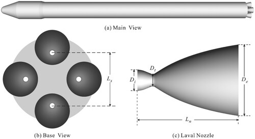
Figure (a,b) shows the main and base view of the four-engine rocket model. Four identical Laval nozzles are mounted on the rocket base plate and the distance of the nonadjacent nozzles, Ls, is 1.82 times as the diameter of the nozzle exit, De. As shown in Figure (c), the Laval nozzle has an area ratio (Dt/De) of 0.17. The diameter of the Laval nozzle inlet, Di, and the nozzle length, Ln, are 0.3 and 1.42 times as the diameter of the nozzle exit, De.
Figure 1. Three-dimensional geometry of the four-engine rocket and its parameters.
2.2. Three-dimensional mesh
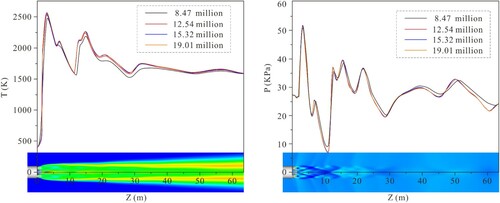
In the meshing process, structured grids are used to establish the three-dimensional computational model of the four-engine rocket. As shown in Figure , local mesh refinement is presented to solve near-wall flow. In general, the mesh density has a significant effect on the accuracy of the simulation result. The verification of grid independence cannot be ignored if high precision and computation speed is desired. In this paper, four mesh models with different quantities (8.47, 12.54, 15.32, and 19.01 million cells) are compared to select a suitable grid. Figure displays the temperature and pressure distribution along the axis of the nozzle from different mesh models at a flight altitude of 10 km. The numerical results are consistent, except for the temperature and pressure data calculated by using the mesh model of 8.47 million cells. Sufficient accuracy can be achieved by using the grid model of 12.54 million cells, which is used in our next simulations. Since the temperature and pressure change abruptly near the wall, near-wall meshes must be encrypted to obtain accurate simulation results. In this paper, the grid length at the first cell center in the proximity of wall is 0.003 m.
Figure 2. Three-dimensional computational mesh of the four-engine rocket.
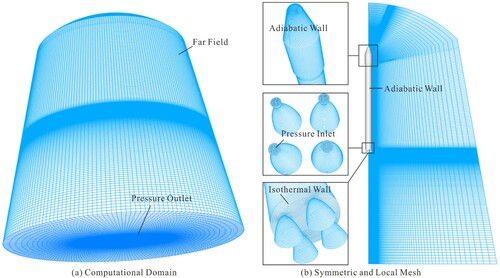
Figure 3. The nozzle axial temperature and the pressure of the four mesh models.
There are five types of boundary conditions in our numerical simulations. The pressure, temperature, and velocity of far-field are the same with freestream. The outlet pressure is defined as the ambient pressure. All solid walls are considered adiabatic, excepting the rocket tail which has an isothermal wall of 300 K. The nozzle inner wall is defined as an adiabatic wall in non-reacting flow, whereas it is considered an isothermal wall of 600 K in the reacting flow. The total pressure and temperature of the Laval nozzle inlet are 18.66 MPa and 3800 K, respectively. The species concentrations of the inlet of rocket gas are listed in Table .
Table 1. Mole fractions of rocket gas at the nozzle inlet and air.
3. Numerical methods
To simulate the afterburning effect on the rocket exhaust plume, the supersonic flow model is established based on the RANS equations, and then the finite-rate chemical kinetics is used to calculate the secondary combustion of carbon monoxide and hydrogen. The three-dimensional governing equations for mass, momentum, and energy are presented by the following (Vatsa & Wedan, Citation1990):
(1)
(1) where U is conservative variable, F1, F2, F3 are the inviscid flux terms, and G1, G2, G3 are the viscid flux terms. These variables can be written as:
(2)
(2)
(3)
(3) where u, v, w are the velocity components of x, y, and z directions, Yi is the mass fraction of species, and D is the diffusivity constant.
When the velocity of four-engine rocket exhaust plume was speeded up to 5 Mach number, the significant non-linear inertial effect in the Navier–Stokes equations tends to overcome the damping effects of viscosity. The material effect that these small-scale turbulent motions have on the mean flow is usually modeled with a separate stress field. In such situations, it is common to apply the concepts of either time averaging (an integral average over a sufficiently long period of time) or ensemble averaging (an average at the same instant, over a repeated number of realizations). The stress fields so obtained allow a description of the averaged effects of momentum, thermal and species mixing due to turbulence. In the realizable k-ϵ turbulence model, the Boussinesq relation is used to obtain Reynolds-stresses from the modeled eddy viscosity μt and the available mean-strain tensor:
(4)
(4) where
(5)
(5)
The model consists of the following transport equations for the kinetic energy k and the turbulent dissipation rate ϵ (Shih et al., Citation1995):
(6)
(6) and
(7)
(7)
The constants of this model are given by:
(8)
(8)
Due to the short combustion duration and incomplete combustion of liquid propellant in the rocket engine chamber, the carbon monoxide and hydrogen exit from the Laval nozzle and react easily with oxygen to produce carbon dioxide and water vapor. The finite-rate chemical kinetics model is used to simulate the three-dimensional afterburning process in the exhaust plume. The afterburning reaction r based on the law of mass action can be written by (Frey & Tien, Citation1979):
(9)
(9) where
and
are the stoichiometric coefficient of species l in reactant and product of chemical reaction r. The rate of production ωlr can be presented by:
(10)
(10) where
(11)
(11) In Equation (11), NT and NP are the exponents of temperature and pressure. The rate of change of the product concentrations is given by Kfr multiplied by the product of the reactant concentrations raised to that reactant’s exponent. The backward rate constant, Kbr, is determined from:
(12)
(12) The change of value in Gibbs free energy
r can be written by:
(13)
(13)
The reaction parameters of the afterburning of the rocket exhaust gas are listed in Tables. In Table , the CO/H2/Air chemical mechanisms are presented. The preexponential factor, temperature exponent, and the activation energy for each afterburning reaction are taken from (Li et al., Citation2010). The compositions of third body for the trimolecular reaction are listed in Table .
Table 2. Reaction parameters of H2/CO afterburning.
Table 3. Third body coefficients of H2/CO afterburning.
The DOM has been used to simulate the radiation heat transfer, which is highly accurate and can be easily solved with flow equations. The DOM model, which considers the radiative transfer equations in the direction as a field equation, was proposed by Chandrasekhar (Citation1960). The radiative transport equation (RTE) for an absorbing, emitting, and scattering gray medium is written as:
(14)
(14) where I is the radiation intensity,
and
are the unit vectors representing the direction of a radiation, κ and γ are the absorbtion and scattering coefficient, respectively. Ω is the solid angle, and the blackbody radiation intensity I* is proportional to the fourth power of the temperature.
(15)
(15) where n is the refractive index, σ is the Stefan–Boltzmann constant.
Integrating the RTE over a finite volume element V and a solid angle element Ωi, the Equation (14) can be presented by:
(16)
(16) In Equation (16), Γ is the surface of a finite volume element,
is the outward surface normal of V.
4. Simulation model validation
A comparison between numerical results and wind tunnel test data (Mehta et al., Citation2013) was carried out to verify the accuracy of our model. Figure shows three-dimensional geometric model and computational mesh of the four-cluster rocket.
Figure 4. Geometric and mesh model for the four-cluster rocket.
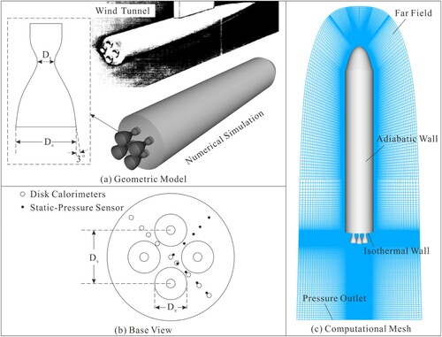
The exit half-angle 3 degrees bell-shaped nozzle had a throat diameter (Dt) of 21.46 mm and an exit diameter (De) of 74.68 mm. The fuel and oxidizer of the rocket engine are JP-4 (kerosene-based) and liquid oxygen. The thrust chamber has a total pressure of 4.1 MPa and a temperature of 3470 K, respectively. Nine disk calorimeters and static-pressure sensors are mounted on the rocket base to monitor the heat flux and pressure, respectively. The detailed descriptions of the engine and geometric parameters can be found in References (Musial & Ward, Citation1961; Mehta et al., Citation2013). Figure displays a comparison between the numerical results of above model and the wind tunnel test data under different altitudes. The wind tunnel conditions of different altitudes are shown in Table . As shown in Figure (a), the exhaust plumes expand rapidly as the nozzle pressure ratio increases. For the different nozzle pressure ratios, the results between our present computation and Reference (Mehta et al., Citation2013) have the same shock structure and Mach number distribution. The base heat fluxes (Figure (b)) and pressure (Figure (c)) of numerical results are qualitatively coherent with the wind tunnel test data, which prove the validity and accuracy of this model.
Figure 5. Comparisons of the Mach contours (a), base heating rate (b), and base pressure (c).
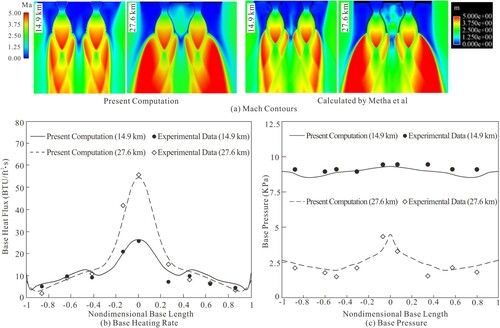
Table 4. Inflow conditions at the nozzle inlet of 14.9 and 27.6 km.
5. Results and discussion
To investigate the afterburning effect on the four-engine rocket exhaust flow field, we next simulate the reacting flow and compared it with the non-reacting flow under different altitudes by using the numerical model, which was described above. Table provides the pressure, temperature, and velocity of far-field boundary conditions at six flight altitudes. The ambient pressure changes from 11,960 Pa to 300 Pa, but the environment temperature varies less significantly at different altitudes.
Table 5. Freestream parameters under different numerical simulation cases.
Figure shows the comparison of Mach number contours between reacting (lower part of subgraphs) and non-reacting flows (upper part of subgraphs). The computational results provide a clear shock construction of the whole flow field, such as plume-induced shock, barrel shock, shock reflection, and plume boundary.
Figure 6. Mach number contours of reacting and non-reacting flows under different altitudes.
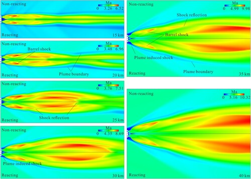
The nozzle pressure ratio increases with the increase of flight altitudes, and the moderately under-expanded exhaust plumes are rapidly developing into high under-expanded gas jet flows. The shock reflection moves towards the downstream divergent section. In cases 1 and 2, the interactive compression of exhaust plumes is not obvious, but a significant interaction of multi-plumes can be observed in cases 3–6. Moreover, the plume-induced shock becomes closer to the rocket base at high altitudes. As shown in Equation (13), the afterburning effect causes the increment of exhaust temperature and local acoustic velocity, which makes Mach number of the reacting flow decrease slightly, unlike those in non-reacting flow.
(13)
(13) where V is the velocity of exhaust plume, a is the local acoustic velocity, r is the adiabatic exponent of gas mixture, R is the gas constant, T is the thermodynamic temperature.
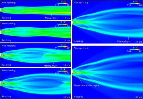
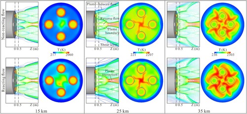
Figure displays the comparison of temperature contours between reacting (lower part of subgraphs) and non-reacting flows (upper part of subgraphs). For the low altitudes, the rocket exhaust plume is attenuated by the interaction and mixing of the shock with the dense shear layer at the plume boundary which may lead to the Kelvin–Helmholtz instabilities. The higher altitude results in larger shear forces and pinches the jet sooner, leading to an axial increase in the turbulent mixing layer. The thicker mixing layer at high altitude has an advantage for the afterburning reaction. In practice, the temperature distributions between reacting and non-reacting flows show no obvious difference in cases 5 and 6. However, a significant temperature increment occurs in case 1 after considering secondary combustion.
Figure 7. Temperature contours of reacting and non-reacting flows under different altitudes.
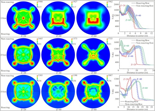
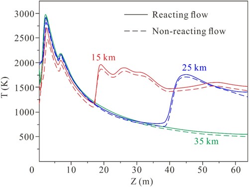
To obtain a quantitative estimate of the afterburning effect on thermal environment of the four-engine rocket under different altitudes, the planar static temperature contours for cases 2, 4, and 6 at Z = 20, 40, and 60 m are presented, where Z = 0 equals to the rocket base, as shown in Figure . The lower and upper of the planar temperature subgraphs represent the reacting and non-reacting flows. The curve graphs show the temperature distributions along the connection line of nonadjacent nozzles between reacting (solid line) and non-reacting flows (dotted line). Different color areas correspond to the temperature increment at Z = 20 (in red), 40 (in blue), and 60 m (in green), respectively. When taking into account the afterburning effect in calculations, the biggest increase in temperature occurred in the planar of Z = 60 m with the same flight heights, while the temperature increment at the planar of Z = 20 m is the smallest. An increase in exhaust plume speed reduces the entrainment. Jets in coflow have a decaying entrainment coefficient with axial distance when fully developed (Mungal, Citation2001). However, with the increase of the axis direction, the mixing layer of the exhaust plume becomes thicker, which is beneficial for the afterburning effect. Therefore, a significant increase in temperature can be seen when the exhaust plume far away from the nozzle exit. Meanwhile, the temperature in the jet core is almost insensitive to afterburning reactions in the near-field area. As the mixing layer reaches the jet centerline, however, the increase in temperature in the central part of the reacting flow becomes significant. With the same cross sections, the temperature increment of reacting flow for the case of 15 km was higher than that of the case of 25 km. There is no significant difference in the temperature of reacting and non-reacting flows for the case of 35 km, since a high altitude with low oxygen content has unfavorable influence on the afterburning reactions.
Figure 8. Planar static temperature contours for cases of altitudes 15, 25, and 35 km.
The afterburning effect mainly occurs in the mixing layer of the air and exhaust gas. It can be seen clearly from Figure that the temperatures of the reacting and non-reacting flows have no significant difference in the center line of the flow field. The strongest interaction effect occurs along the center line of the exhaust plumes, making it difficult for oxygen in air to reach the core of the flow field. As a result, the temperature distribution along the center line is insensitive to afterburning effect.
Figure 9. Temperatures distribution along the plume centerline for cases of altitudes 15, 25, and 35 km.
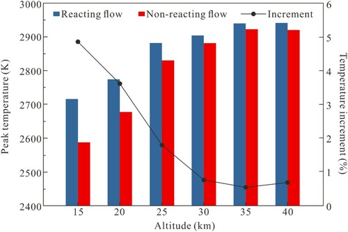
The maximum temperatures in the rocket flow field with and without the afterburning effect are shown in Figure . The differences between reacting and non-reacting flows decrease as the flight height increasing, which also accounts for the fact that secondary combustion can proceed easily at low altitude, and with more difficulty at a high altitude. However, since the maximum temperature region occurs in the external flow region where the velocity of exhaust gas is high, it can be found that the peak temperature increments caused by afterburning are less than 5% at all altitudes.
Figure 10. Peak temperature of reacting and non-reacting flows.
The thermal environment of the exhaust plume becomes more rigorous because of the afterburning effect, which may affect the safety of the rocket flight. The studies on the heat flux of the rocket base between reacting and non-reacting flows could provide the theoretical guidance for the thermal protection designing. Figure shows the rocket base heat flux with and without afterburning reactions for cases 2, 4, and 6. The heat flux is composed of the convection and radiation heat transfer, which can present the thermal environment of the rocket base. As expected, the peak heat flux occurs in the center of the rocket base. Due to the plume interaction effect, the near-field temperature of the exhaust gas in the core region is higher than that at the edge region, and the flow reversal results in high heat flux on the base center.
Figure 11. The heating rates of the rocket base for cases of altitudes 15, 25, and 35 km.
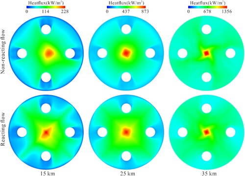
As shown in Figure , strong recirculation is formed near the rocket base surrounded by the inflow, exhaust flow, and rocket wall. The recirculation flow reaches the rocket base, and then heats it up. Surprisingly, the afterburning effect has little influence on the temperature of the exhaust plume in the recirculation region, resulting in no apparent difference on the convection heat transfer between reacting and non-reacting flows. The increment of the maximum heating rates by afterburning effect is varied from 9.4% to 2.7% as flight altitude increases from 15 to 35 km. With the increases of the altitude, more expansion and stronger interaction make the oxygen in air more difficult to reach into the core region of the four plumes and participates in the afterburning reactions. Hence, the afterburning has a mirror significant effect on the reverse flow, especially in the hypoxic high altitude. The planar static temperature contours of reacting flow for the cases 2, 4, and 6 at Z = 0.5 m basically coincide with those of the non-reacting flow, suggesting that the change of convection heat flux caused by the afterburning can be ignored at a high altitude. On the other hand, a mixing layer near the nozzle exit that is too thin is unfavorable for afterburning reaction. The radiation heat transfer induced by the exhaust gas of reacting and non-reacting flows is also very similar. In short, the afterburning effect has a substantially minor influence on the overall thermal environment of the four-nozzle rocket exhaust plume. There is no significant change of the heat flux of the rocket base between reacting and non-reacting flows in the high altitude due to the negligible afterburning reactions near the nozzle exit.
Figure 12. The isogram and cross section of temperature near the rocket base for cases of altitudes 15, 25, and 35 km.
6. Conclusions
In this study, the liquid rocket exhaust flow fields with afterburning are simulated by using RANS equations and the finite-rate chemical kinetics. The model is first validated by a comparison with the wind tunnel test data of the four-cluster rocket. Based on the verified model, comparisons of thermal environment of the four-engine liquid rocket between reacting and non-reacting flows are performed under six different altitudes. The main conclusions that can be drawn are as follows:
The afterburning effect causes a slight decrease in Mach number and a weak increase in peak temperature (no more than 5%) of the rocket exhaust flow field.
The afterburning reaction mainly occurs on the mixing layer between exhaust gas and air.
At the same altitude, the afterburning has a greater significant effect on the flow field for a larger distance from the nozzle exit. With the same cross sections, the temperature increment of the reacting flow at low altitude is higher than that at high altitude.
When flight altitude is increased from 15 to 35 km, the increment of maximum heat flux caused by afterburning decreases from 9.4% to 2.7%. The difference of the rocket base heat flux between reacting and non-reacting flows can be neglected in hypoxic high altitudes.
In an actual flight, the rocket attitude can be adjusted by swiveling the individual Laval nozzle, which leads to a more complex flow field. Due to a limited amount of computational resources, the exhaust plume flow with a moving nozzle was not simulated in this paper. In the future, we will try to simulate the rocket plume with a moving nozzle by using dynamic overset grids.
Acknowledgements
The authors would like to thank Professor Junfeng Zhang for reviewing this article and providing suggestions.
Writer of the original draft: Zhitan Zhou; Editors and reviewers: Yiyin Bao, Peijie Sun, and Guigao Le.
Disclosure statement
No potential conflict of interest was reported by the authors.
References
- Adam, D., Karol, P., Szymon, K., Jacek, G., & Agnieszka, E. (2020). Preliminary results from Hedgehog Rexus project-a sounding rocket experiment on accelerations, vibrations and heat flow. Acta Astronautica, 177, 80–85. https://doi.org/https://doi.org/10.1016/j.actaastro.2020.07.016
- Chandrasekhar, S. (1960). ‘The equation of transfer,’ Radiative Transfer, Dover, New York, 1960, Chap. 1. https://doi.org/https://doi.org/10.1007/10057805_11.
- Crocco, L., Harrje, D. T., & Reardon, F. H. (1964). Velocity effects in transverse mode liquid propellant rocket combustion instability. AIAA Journal, 2(9), 1631–1641. https://doi.org/https://doi.org/10.2514/3.2631
- Davis, S. G., Joshi, A. V., Wang, H., & Egolfopoulos, F. (2005). An optimized kinetic model of H2/CO combustion. Proceedings of the Combustion Institute, 30(1), 1283–1292. https://doi.org/https://doi.org/10.1016/j.proci.2004.08.252
- Frey, A. E., & Tien, J. S. (1979). A theory of flame spread over a solid fuel including finite-rate chemical kinetics. Combustion and Flame, 36, 263–289. https://doi.org/https://doi.org/10.1016/0010-2180(79)90064-6
- Ghalandari, M., Shamshirband, S., Mosavi, A., & Chau, K. W. (2019). Flutter speed estimation using presented differential quadrature method formulation. Engineering Applications of Computational Fluid Mechanics, 13(1), 804–810. https://doi.org/https://doi.org/10.1080/19942060.2019.1627676
- Gomez, A., Pérez-Grande, I., & Sanz-Andrés, A. (2018). Uncertainty calculation for spacecraft thermal models using a generalized SEA method. Acta Astronautica, 151, 691–702. https://doi.org/https://doi.org/10.1016/j.actaastro.2018.05.045
- Harper, E. Y., & Witte, A. B. (1963). Experimental investigation of heat transfer rates in rocket thrust chambers. AIAA Journal, 1(2), 443–451. doi:https://doi.org/10.2514/3.1552
- Kassoy, D. R. (2017). Thermomechanical concepts and modeling for stability physics in liquid-propellant rocket engines. AIAA Journal, 55(6), 2043–2051. https://doi.org/https://doi.org/10.2514/1.j055386
- Li, J., Zhao, Z., Kazakov, A., Chaos, M., Dryer, F. L., & Scire, J. J. (2010). A comprehensive kinetic mechanism for CO, CH2O, and CH3OH combustion. International Journal of Chemical Kinetics, 39(3), 109–136. https://doi.org/https://doi.org/10.1002/kin.20218
- Ma, P. C., Wu, H., Ihme, M., & Hickey, J. P. (2018). Nonadiabatic flamelet formulation for predicting wall heat transfer in rocket engines. AIAA Journal, 56(6), 2336–2349. https://doi.org/https://doi.org/10.2514/1.j056539
- Mehta, R. C. (1981). Estimation of heat-transfer coefficient in a rocket nozzle. AIAA Journal, 19(8), 1085–1086. https://doi.org/https://doi.org/10.2514/3.7846
- Mehta, M., Canabal, F., Tashakkor, S. B., Smith, S. D., & Alabama, H. (2013). Numerical base heating sensitivity study for a four-rocket engine core configuration. Journal of Spacecraft and Rockets, 50(3), 509–526. https://doi.org/https://doi.org/10.2514/1.A32287
- Mikatarian, R. R., & Pergament, H. S. (1969). Effects of altitude on radar attenuation in nonequilibrium afterburning rocket exhaust plumes. AIAA Journal, 7(1), 159–161. https://doi.org/https://doi.org/10.2514/3.5056
- Mungal, D. (2001). Direct measurement of entrainment in reacting/nonreacting turbulent jets. Combustion and Flame, 124(3), 370–386. https://doi.org/https://doi.org/10.1016/S0010-2180(00)00211-X
- Musial, N., & Ward, J. (1961). Base flow characteristics for several four-clustered rocket configurations at Mach numbers from 2.0 to 3.5. NASA TND-1093. https://ntrs.nasa.gov/citations/19980228116.
- Negishi, H., Yamanishi, N., Arita, M., Namura, E., & Ohkubo, S. (2007). Numerical analysis of plume heating environment for H-IIA launch vehicle during powered ascent. Proceedings of the 43rd AIAA/ASME/SAE/ASEE joint Propulsion conference and exhibit, Cincinnati, OH, USA, 8-11 July, 2007. https://doi.org/https://doi.org/10.2514/6.2007-5505.
- Niu, Q., Duan, X., Meng, X., He, Z., & Dong, S. (2019). Numerical analysis of point-source infrared radiation phenomena of rocket exhaust plumes at low and middle altitudes. Infrared Physics & Technology, 99, 28–38. https://doi.org/https://doi.org/10.1016/j.infrared.2019.04.005
- Rana, Z. A., Thornber, B., & Drikakis, D. (2013). Dynamics of sonic hydrogen jet injection and mixing inside scramjet combustor. Engineering Applications of Computational Fluid Mechanics, 7(1), 13–39. https://doi.org/https://doi.org/10.1080/19942060.2013.11015451
- Salih, S. Q., Aldlemy, M. S., Rasani, M. R., Ariffin, A. K., Ya, T., Ansari, N., Yaseen, Z. M., & Chau, K. W. (2019). Thin and sharp edges bodies-fluid interaction simulation using cut-cell immersed boundary method. Engineering Applications of Computational Fluid Mechanics, 13(1), 860–877. https://doi.org/https://doi.org/10.1080/19942060.2019.1652209
- Shih, T. H., Liou, W., Shabbir, A., Yang, Z., & Zhu, J. (1995). A new k-ϵ eddy viscosity model for high reynolds number turbulent flows. Computer & Fluids, 24(3), 227–238. https://doi.org/https://doi.org/10.1016/0045-7930(94)00032-t
- Vatsa, V. N., & Wedan, B. W. (1990). Development of a multigrid code for 3-d Navier-Stokes equations and its application to a grid-refinement study. Computer & Fluids, 18(4), 391–403. https://doi.org/https://doi.org/10.1016/0045-7930(90)90029-W
- Whitefield, P. D., Ross, M. N., Hagen, D. E., Rutter, A., & Hopkins, A. R. (2000). In-situ aerosol emissions characterization in rocket exhaust plumes during projects riso and accent. Journal of Aerosol Science, 31, 222–223. https://doi.org/https://doi.org/10.1016/s0021-8502(00)90231-3
- Xiong, J., Morgan, H., Krieg, J., Liu, F., & Sirignano, W. A. (2020). Nonlinear combustion instability in a multi-injector rocket engine. AIAA Journal, 58(1), 1–17. https://doi.org/https://doi.org/10.2514/1.j058036
- Yao, W., Yuan, Y., Li, X., Wang, J., Wu, K., & Fan, X. (2018). Comparative study of elliptic and round scramjet combustors fueled by RP-3. Journal of Propulsion and Power, 34(3), 772–786. https://doi.org/https://doi.org/10.2514/1.b36721
- Yilmaz, N., Vigil, F., Height, J., Donaldson, B., & Gill, W. (2018). Rocket motor exhaust thermal environment characterization. Measurement, 122, 312–319. https://doi.org/https://doi.org/10.1016/j.measurement.2018.03.039
- Zhou, Z. T., Wang, X., Lu, C. Y., & Le, G. G. (2020). Numerical analysis on thermal environment of liquid rocket with afterburning under different altitudes. Applied Thermal Engineering, 178, 115584. https://doi.org/https://doi.org/10.1016/j.applthermaleng.2020.115584
- Zhou, Z. T., Zhang, L. J., & Le, G. G. (2020). Numerical study for the flame deflector design of four-engine liquid rockets. Engineering Applications of Computational Fluid Mechanics, 14(1), 726–737. https://doi.org/https://doi.org/10.1080/19942060.2020.1761453