
Abstract
Finding new efficient connectors or improving existing ones are important issues in timber construction. This research investigates an innovative large-diameter dowel-type connection by using a finite elements model calibrated with experimental results. This connection is made of a large-diameter single dowel reinforced by means of a steel plate with a vulcanised rubber layer. The steel plate shape, thickness and dimensions, the rubber stiffness, the steel mechanical properties, etc., are parameters that may influence the critical load of the plate. The joint load-bearing capacity is also highly depending on the load direction to the grain. Those parameters are investigated using FE modelling and discussed in order to propose design recommendations.
Introduction
When designing timber structures, a connection capacity is often lower than that of the members it is connecting. Moreover, as minimum distances between connectors or edge distances must be respected, connections tend to become large and space-consuming. Connections are thus often regarded as the weakest part of a timber structure. Their complexity and high cost may sometimes make timber structures uncompetitive compared to other structures.
Moreover, dowel-type fasteners connections are often responsible for failure in timber structures: on one hand, holes (to place fasteners) reduce cross-section of the element; and on the other hand dowels loaded at an angle to the grain induce shear and local tension perpendicular to the grain in the wooden element (dangerous stresses for this material).
Hence, finding new connectors and improving existing ones are important issues in timber construction (Borri, Corradi and Speranzini Citation2013; Steiger et al. Citation2015; Franke, Franke and Harte Citation2015; Schober et al. Citation2015; Dietsch and Brandner Citation2015).
Among reinforced joints, reinforced dowel-type connections constitute a promising solution to problems listed above. By increasing shear strength and tensile strength perpendicular to the grain in the connection area, reinforcements may reduce connection dimensions and increase load-bearing capacity and/or ductility of the joint. Many reinforcement techniques for such connections have already been proposed, such as glued-on wood-based panels (Blass and Schälde Citation2011), fibreglass (Soltis, Ross and Windorski Citation1998; Chen Citation1999), nail plates (Hockey, Lam and Prion Citation2000; Mastschuch Citation2000), threaded rods and glued-in-rods (Quenneville and Mohammad Citation2000; Steiger et al. Citation2015), textiles (Haller and Birk Citation2006) or self-tapping screws (Hansen Citation2002; Bejtka and Blass Citation2005; Kobel Citation2011; Lathuillière, Bléron, Descamps and Bocquet Citation2015; Klajmonova and Lokaj Citation2015).
Large-diameter dowel in combination with reinforcing screws (Crocetti, Axelson and Sartoni Citation2010) exhibited extremely ductile failure mode and a higher load-carrying capacity (even when minimum distances were not respected), since screws avoided splitting failure of the wooden element. Those encouraging results favoured testing other reinforcements for single large-diameter dowel connections with the aim of reducing problems due to low embedding capacity of wood.
Yang, Crocetti, Larsson and Gustaffson (Citation2015) investigated five different reinforcement techniques for large diameter (i.e. ∼90 mm) single dowel joint (see ), namely reinforcements with: (a) thick steel plate and pre-stressed threaded steel rod, (b) thick steel plate and non-pre-stressed threaded steel rod, (c) glued thin steel plate, (d) glued rubber foil on a thin steel plate and finally (e) steel plates bonded on two glulam elements. In specimens (c) to (e), the hole drilled in the plate is smaller than the hole drilled in the wood.
1 Specimens tested by Yang et al. (Citation2015)
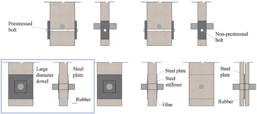
Specimens with reinforcement (c) (see ) exhibited a load-bearing capacity significantly higher than other tests, with an average capacity of 990 kN. They are composed of a single large-diameter dowel (91.5 mm) reinforced with a steel plate glued on a vulcanised rubber layer. Since the hole drilled in the steel plate is smaller than the wood hole (diameter of 102 mm), there is no contact between the dowel and the wood.
Compared to the same specimens but without rubber layer (configuration (d)), the load-bearing capacity of specimen (c) was 639% higher in average (Yang et al. Citation2015). With rubber layer, though, the observed failure mode was a fully wood shear failure around the bonding area.
This high load-bearing capacity has several explanations:
The load-bearing capacity of a dowel-type fastener is influenced by the yield moment of the dowel, the embedding capacity of the timber and the withdrawal strength of the dowel.
As the dowel has a large diameter, the yield moment is considerably increased. Problems due to relative low embedding capacity of wood are considerably reduced since there is no contact between the wood and the dowel.
Using a single dowel prevents strength reduction due to the non-uniform distribution of loads among dowels within a group.
The vulcanised rubber layer induces a uniform distribution of shear stresses in the adhesive bond and therefore increases the load-carrying capacity of the joint (but reduces its stiffness), as highlighted by Danielsson and Bjornsson (Citation2005).
Thanks to its high strength, this connection is suitable for heavily loaded applications – for instance, the hinge connection between the foot of a timber arch constituting a bridge and a steel plate cast in its concrete foundation.
The present research focuses on developing a reliable finite element model (using ABAQUS software) of this reinforced joint, in order to undertake parametric studies and propose design recommendations.
Materials and methods
Finite element model and method
Because of the symmetry, only half the connection is modelled (see ), with solid elements C3D8(H) – 3 dimensional and 8-node linear brick elements with a hybrid integration.
2 Boundary conditions
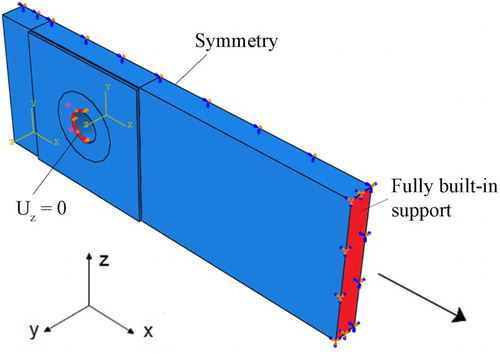
Other boundary conditions are illustrated in .
In such a connection, the out-of-plane displacement of the steel plate (due to a buckling instability) would be delayed or even prevented by the friction induced by the dowel on the inner hole surface. The ‘zero out-of-plane displacement’ condition (‘Uz = 0’) around the hole accounts for this phenomenon.
Materials properties
The timber used in the connection is a spruce glulam corresponding to a GL30c according to European Standard 14080. Wood is modelled as an elastic orthotropic material, with properties summarised in (from (Dahl Citation2009) and the European standard NBN-EN-1194).
Table 1 Wood properties
Rubber is SBR (styrene-butadien) number 61 60 367, modelled as a linear hyperelastic material. Hyperelastic materials are described by a strain energy potential, which defines the strain energy stored in the material per unit of reference volume as a function of the strain at that point in the material. The Neo Hook model implemented here uses the polynomial form of the strain energy function by using only the first term C10. The material is thus entirely defined by C10 = G0/2 = 0.3195 (with G0 the rubber shear modulus) and D1 (the material compressibility) equal to 0 (Danielsson and Bjornsson Citation2005).
Since the rubber is very flexible, the glue stiffness has not a great influence on the FE model. Therefore, the glue is modelled through a simplified ‘tie interaction’ between the steel plate and the wood.
The steel plate is modelled either as an elastic material, or an elasto-plastic material (depending on the analysis conducted). Its Young modulus is 210 000 MPa, its Poisson’s ratio 0.3 and its yield strength 355 MPa. However, according to Eurocode 3 [EN 1993-1-8:2005], the load-bearing strength of a steel plate in this type of connection is actually higher than its yield strength. Hence, a fictitious yield strength fy′ is defined in [EN 1993-1-8:2005] as:With
Where (for end and edge bolts):
the minimal value of
is the end distance from the centre of the hole to the end steel plate end.
is the hole diameter
is the steel ultimate strength = 470 MPa
is the steel yield strength = 355 MPa
is equal to 2.5
are the partial security factors
This fictitious yield strength value is here equal to 713 MPa.
Loading
In the FE model, the load is applied directly on the steel plate to avoid modelling the dowel, and thus heavy calculations and increased computation time. Hence, the load is modelled through a surface tension applied on half the diameter of the cylinder. Two different load distributions are considered (see ): a uniform distribution and a cosinus-shaped distribution (in order to better represent the real bolt bearing behaviour).
3 Loading cases (uniform distribution vs. cosinus-shaped distribution)
Non-linear buckling of the steel plate
Since the hole drilled in the steel plate is smaller (diameter of 91.5 mm) than the hole drilled in the wood (102 mm), the part of the steel plate which is not glued on the timber may be subjected to buckling.
Both linear buckling and non-linear buckling analyses were performed by means of a FE model. The aim of the linear buckling analysis is just to find a proper shape for the initial imperfection, which is then used as an input for the non-linear buckling analysis.
Linear buckling analysis is based on eigenvalues and provides the critical load, i.e. the load for which the model stiffness matrix becomes singular.
The method is the following: for each possible mode of buckling (the first mode being the most likely to occur), the FE analysis provides an eigenvalue. The critical buckling load is then obtained by multiplying this eigenvalue with the load applied in the model.
Although linear buckling analysis is usually used to obtain an approximation of the critical load, in this case, however, it has given an appropriate buckling shape but unrealistic value for the critical load. The presence in the connection of a rubber layer – a non-linear material – or the fact that no preload has been applied could explain those results.
Non-linear buckling analysis offers more accurate results for the critical load since it takes into account plastic deformations, initial imperfections, non-linear behaviour and also large deflection responses. But in order to perform such an analysis, an initial perturbation has to be introduced in the model. In the present research, this initial imperfection (i.e. a proper buckling shape) comes from the previously performed linear buckling analysis.
It has to be noted, though, that further numerical analyses showed that initial imperfection did not have a significant influence on the connection behaviour.
Model calibration
Failure mode observed experimentally is a brittle failure of the wood (Yang et al. Citation2015). For the FE model to replicate and predict this failure, a wood failure criterion must therefore be implemented in the model.
A failure criterion is a mathematical expression describing an opened or closed strength surface in a strength space. The safe state is defined inside this strength surface. If some combinations of stresses are too high, the criterion value is outside the strength surface: failure occurs in the material. The most popular criteria to describe a wood brittle failure are Norris criterion, Hankinson formula and Tsai–Wu criterion.
Norris criterion (Norris Citation1962) consists in three different equations, each one corresponding to a principal plane of the orthotropic material. Failure is avoided if the three equations are respected simultaneously. This criterion does not take into account the interaction between stresses and makes no distinction between tensile and compressive strength, though wood behaviour is highly different depending on the load direction.
Tsai–Wu criterion (Tsai and Wu Citation1971) is expressed through only one formula and could thus be a faster way to get the maximum load. Moreover, it takes into account the interactions between stresses and distinguishes tensile strength from compressive strength.
The criteria are implemented in the FE model ABAQUS through a new field output in the results file; the load-bearing capacity of the connection is thus obtained through post-treatment of results. In this research, the connection failure load is defined as the load for which the criterion value (whether it is a Norris or Tsai–Wu criterion) is reached (i.e. close to 1) at one element centroid of the wooden part of the connection.
The failure load obtained with the FEM using Norris criterion is closed to the failure load value obtained using Tsai–Wu criterion. Tsai–Wu criterion is preferred since it allows distinguishing tensile and compressive strengths of the timber and takes into account interactions between stresses.
The reference values for wood strengths are found in the literature. Two sets of strength values (obtained through experimental tests on small clear wooden specimens) are considered: Hemmer (Citation1985) and Eberhardsteiner (Citation2002) (see ).
Table 2 Hemmer and Eberhardsteiner strength values
The FE model is calibrated on three different tests. ‘Test A’ corresponds to the connection illustrated on c and described in the Introduction section. ‘Test B-a’ and ‘Test B-b’ (see ) are configurations that have been studied and tested in (Gustafsson Citation2007): The dowel diameter and the steel hole diameter are equal to 32 mm while the timber hole diameter is 35 mm.
4 Reinforced dowel joints with vulcanised rubber layer and a steel plate – Tests B: a load perpendicular to the grain; b load parallel to the grain (Gustafsson Citation2007)
Comparison between numerical predictions of failure load and experimental results tends to prove that Hemmer’s set of strength values – combined to a cosinus-shaped load distribution – gives more accurate results (see ).
Table 3 Comparison Numerical results vs. experimental results (load in [kN])
However, failure loads still do not perfectly match test results, especially for a load perpendicular to the grain. Strength values perpendicular to the grain (i.e. and
) are thus calibrated until numerical results match experimental results. presents the final strength values implemented in the model. compares experimental results with predictions from the calibrated FE model.
Table 4 Strength values used in the FE model [MPa]
Table 5 Comparison numerical results (calibrated model) VS experimental results (load in [kN])
It should be noted, though, that strength values calibration is very sensitive to small changes: if mesh or load distribution are changed, calibrated values are no longer valid. For instance, regarding test 3, if a factor 2 is applied to the mesh size, the maximum load is affected by a factor 1.18.
Parametric study
A parametric study regarding the plate geometry (shape, dimensions and thickness) is undertaken to optimise the connection and give design recommendations, with a dual focus:
Reduce concentrations of stresses located around the hole in the steel plate. By doing so, the critical buckling load of the steel plate could be increased.
Simultaneously have a more homogeneous distribution of stresses in the wood located under the bondline, and thus increase the whole connection load-bearing capacity (since the connection failure is a wood failure).
The steel plate shapes investigated are illustrated in . Shapes 1 to 4 aimed at reducing concentrations of stresses located around the hole by optimising the non-glued zone. Shapes a to d investigated the influence of the hole diameter and the steel plate dimensions on the connection behaviour, in order to minimise the amount of steel used in the connection.
5 Geometry of the steel plate – dashed lines = non-glued zone (dimensions in [mm])
![5 Geometry of the steel plate – dashed lines = non-glued zone (dimensions in [mm])](/cms/asset/851e4f4f-3357-4ce9-9cde-cc9e3de317f6/ywpj_a_1273666_f0005_b.gif)
The thicknesses studied varied between 2 and 13 mm, considering two cases: a uniform thickness along the steel plate, or a steel plate with a reduced thickness but combined with a stiffener (another steel plate with smaller dimensions, surrounding the hole).
The numerical parametric study also focused on the added-value of using a rubber interlayer. The same connection with and without rubber was thus modelled and behaviours compared.
The load-bearing capacity of the connection depending on the load direction (to the grain) was also studied.
Results and discussion
FEM results show that Shape ‘2’ leads to a lower connection stiffness and reduced steel plate critical load, accompanied with much higher stresses in the wood, as shown in . As a reminder, a value of the wood failure criterion close to 1 means a wood failure; hence, the less the value of this criterion (for a same applied load), the stronger the connection.
Table 6 Influence of the steel shape on the stresses in the wood – Changing the glued area
Shape ‘1’ seems to be the best solution, resulting in lower stresses in the wood than Shapes ‘3’ and ‘4’ (and therefore an increased connection load-bearing capacity).
Shapes ‘b’ and ‘c’ are highly unfavourable regarding both steel plate and wood behaviours. Shape ‘a’ gives more promising results (see ).
Table 7 Influence of the steel shape on the stresses in the wood – changing the plate dimensions
Numerical analysis also highlight that buckling loads reached with a 13 mm plate or with a 8 mm plate combined to 5 mm stiffener are quite close. Distributions of shear stresses in the wood in both cases are also comparable, as shown in . Adding a steel stiffener is thus a good way to increase the critical load while saving steel.
Table 8 Influence of the steel plate thickness on the steel buckling load and on stresses in the wood
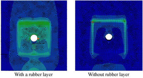
Parametric study shows the significant influence of the rubber on the joint load-bearing capacity. For the same connection configuration (load parallel to the grain), joint without rubber interlayer only reached 183.6 kN, while joint with rubber interlayer reached a failure load of 283.6 kN (∼54.4% increase in capacity). When it comes to load perpendicular to the grain, this increase in load-bearing capacity is 42.8%. This improvement is due to the more uniform distribution of shear stresses occurring in the wood under the bondline thanks to the presence of rubber interlayer, as visible in . For a load parallel to the grain, the connection with a rubber layer (, left side) shows a uniform stress distribution under the plate with stress concentrations on both sides of the hole. When the connection has no rubber layer (, on the right), the stress distribution is no longer uniform and stresses are concentrated under the upper side of the steel plate.
6 Results of Tsai–Wu criterion from the FE model, under a load parallel to the grain: on the left, model with a rubber layer; on the right, same connection without any rubber layer
FEM analysis also shows that, as expected, the performance of the connection is highly dependent on the load direction to the grain: The load-bearing capacity of the reinforced joint is reduced by 75.5% if the load is applied perpendicular to the grain.
A possible improvement could be to include the dowel in the finite element model. In the proposed model, indeed, the load is applied directly around the hole through a load distribution – either uniform or cosinus-shaped. The issue is that this distribution is not perfectly realistic (the real distribution is somewhere in between) and the FEM results are sensitive to this distribution. Modelling the dowel could therefore give more accurate results. Moreover, the presence of the dowel would prevent relative displacement between the hole and the steel plate occurring in the FE model. Indeed, such a displacement is not realistic since the dowel ‘holds’ the steel plate in place.
Conclusions
Joints in timber structures are often complex, complicated to manufacture and therefore expensive. Moreover, joints and especially dowel-type fasteners joints are often responsible for failures in timber structures. Indeed, since timber is weak in shear and in tension perpendicular to the grain, brittle failures such as splitting and shear-plug extraction often occur in such connections. Reinforcing dowel-type connections may reduce those stresses and avoid cracks propagation, therefore leading to reduced connection dimensions, higher ductility and higher load-bearing capacity. Therefore, many reinforcement techniques have been proposed such as nail plate, glued-in rods, fibreglass, self-tapping screws, …
This research investigated a large-diameter single dowel joint reinforced with a rubber interlayer using a FE model calibrated on experimental results from three different tests.
Buckling analysis has then been performed on a reference model to study the influence of parameters such as the geometry of the steel plate, the initial imperfections, material properties, load distribution, … This parametric study allowed defining an appropriate configuration for the steel plate, by highlighting the following conclusions:
Mechanical properties of the steel plate are of paramount importance. Too low mechanical properties could lead to failure in the steel plate before failure in the timber.
Reducing the glued area under the steel plate may be beneficial to reduce stress concentration in the plate but it may affect the critical load of this last one. Moreover, it leads to higher stress concentration in the wood.
Adding a steel stiffener on the plate allows increasing the critical load of the plate without affecting stress distribution in wood.
Using a rubber with higher stiffness may reduce shear displacement of the plate and stresses in wood.
Using a rubber layer increases the maximum load by approximately 54.4% if the load is parallel to the grain and by 42.8% if the load is perpendicular to the grain.
The joint is not significantly sensitive to initial imperfections.
The load-bearing capacity of the reinforced joint is reduced by 75.5% if the load is applied perpendicular to the grain.
The studied single large-diameter reinforced dowel connection has been shown to be highly performant. Future numerical improvements could include the dowel in the finite element model. The FE model could also be transposed to the study of other configurations of this connection, in order to avoid a brittle failure in the wood cross-section.
Acknowledgements
The authors express their gratitude to COST FP1101 action for funding this Short Term Scientific Mission. The University of Lund is also gratefully acknowledged for kindly hosting one of the authors when conducting this research.
References
- Bejtka, I. and Blass, H. 2005. Self-tapping screws as reinforcements in connections with dowel-type fasteners. Karlsruhe: Universität Karlsruhe.
- Blass, H. and Schälde, P. 2011. Ductility aspects of reinforced and non-reinforced timber joints. Engineering Structures. 33(11): 3018–3026. doi: 10.1016/j.engstruct.2011.02.001
- Borri, A., Corradi, M. and Speranzini, E. 2013. Reinforcement of wood with natural fibers. Composites Part B: Engineering. 53: 1–8. doi: 10.1016/j.compositesb.2013.04.039
- Chen, C. 1999. Mechanical behaviour of fiberglass reinforced timber joints. PhD Thesis, Swiss Federal Institute of technology, Lausanne, Switzerland.
- Crocetti, R., Axelson, M. and Sartoni, T. 2010. Strengthening of large-diameter single dowel joints. Lund, Sweden: SP Technical Research institute of Sweden.
- Dahl, K. 2009. Mechanical properties of clear wood of Norway Spruce. Tronheim, Norway: NTNU Tronheim.
- Danielsson, H. and Bjornsson, P. 2005. Strength and creep analysis of glued rubber foil timber joint. Lund, Sweden: Lund University.
- Dietsch, P. and Brandner, R. 2015. Self-tapping screws and threaded rods as reinforcement for structural timber elements – a state-of-the-art report. Construction and Building Materials. 97: 78–89. doi: 10.1016/j.conbuildmat.2015.04.028
- Eberhardsteiner, J. 2002. Mechanisches berhalten von fichtenholz – experimentelle bestimmung der biaxialen festigkeitseigenshaften. Wien: Springer-Verlag Wien GmbH.
- Franke, S., Franke, B. and Harte, A. 2015. Failure modes and reinforcement techniques for timber beams – state of the art. Construction and Building Materials. 97: 2–13. doi: 10.1016/j.conbuildmat.2015.06.021
- Gustafsson, J. 2007. Tests of full size rubber foil adhesive joint. Lund, Sweden: Structural Mechanics LTH.
- Haller, P. and Birk, T. 2006. Tailor made textile reinforcements for timber connection. In Proceedings of ninth World Conference on Timber Engineering, Portland, USA.
- Hansen, K. 2002. Mechanical properties of self-tapping screws and nails in wood. Canadian Journal of Civil Engineering. 29: 725–733. doi: 10.1139/l02-059
- Hemmer, K. 1985. Versagensarten des Holzes der Weisstanne unter mehrassige Beanspruchung. Germany: University at Fridericiana.
- Hockey, B., Lam, F. and Prion, H. 2000. Truss plate reinforced bolted connections in parallel strand lumber. Canadian Journal of Civil Engineering. 27(6): 1150–1161. doi: 10.1139/l00-040
- Klajmonova, K. and Lokaj, A. 2015. Round timber bolted joints reinforced with self-drilling screws. Procedia Engineering. 114: 263–270. doi: 10.1016/j.proeng.2015.08.067
- Kobel, P. 2011. Modelling of strengthened connections for large span timber structures. Lund, Sweden: Lund University.
- Lathuillière, D., Bléron, L., Descamps, T. and Bocquet, J.-F. 2015. Reinforcement of dowel type connections. Construction and Building Materials. 97: 48–54. doi: 10.1016/j.conbuildmat.2015.05.088
- Mastschuch, R. 2000. Reinforced multiple bolt timber connections. Vancouver, Canada: University of British Columbia.
- Norris, C. 1962. Strength of orthotropic materials subjected to combined stresses, Report 1816, Madison, Wisconsin, Forest Products Laboratory, Forest Service U.S. Department of Agriculture.
- Quenneville, J.H. and Mohammad, M. 2000. Anti-check bolts as means of repair for damaged split ring connections. In Proceedings of sixth World Conference on Timber Engineering, Whistler, Canada.
- Schober, K.-U., Harte, A., Kliger, R., Jockwer, R., Xu, Q. and Chen, J.-F. 2015. FRP reinforcement of timber structures. Construction and Building Materials. 97: 106–118. doi: 10.1016/j.conbuildmat.2015.06.020
- Soltis, L.A., Ross, R. and Windorski, D. 1998. Fiberglass-reinforced bolted wood connections. Forest Products Journal. 48(9): 63–67.
- Steiger, R., Serrano, E., Stepinac, M., Rajcic, V., O’Neill, C., McPolin, D. and Widmann, R. 2015. Strengthening of timber structures with glued-in rods. Construction and Building Materials. 97: 90–105. doi: 10.1016/j.conbuildmat.2015.03.097
- Tsai, S. and Wu, E. 1971. A general theory of strength for anisotropic materials. Journal of Composite Materials. 5: 58–80. doi: 10.1177/002199837100500106
- Yang, H., Crocetti, R., Larsson, G. and Gustaffson, P. 2015. Experimental study of innovative connections for large span timber structures. In Proceedings of the IASS working groups 12 + 18 International Colloquium 2015, Tokyo, Japan.