
Abstract
The aim of this study was to evaluate the structural health of a 19th-century warehouse located in Trondheim using a drilling resistance device. The building, Kjøpmannsgata 27, is one of the many bryggene which are situated along the river Nidelva. These buildings were used in the past as warehouses and repositories. They represent the peak period of the town’s commercial expansion during the 18th and 19th centuries and are considered an important part of the city’s historical profile. The building has many structural issues, especially in the basement where the structure is in direct contact with the ground. A visual survey of the building was carried out prior to drilling resistance testing. The combination of these two methods was used to locate decayed wood and critical areas in need of repair. The foundation beams were found to be in the worst state of decay. Measurement of the drilling resistance proved to be a useful method for evaluating the condition of the building’s structure, providing the basis to plan its rehabilitation.
Introduction
In order to design an appropriate and efficient intervention plan for the consolidation and restoration of a wooden structure, it is necessary to evaluate its current condition. This is particularly complicated for wooden structures because of the variety in construction techniques and the material is non-homogeneous, anisotropic, and displays visco-elastic behaviour. In addition, degradation is strongly influenced by environmental conditions. In situ inspections and accurate surveys of the changes in the materials and structure due to time and environment are essential for assessing the state of degradation of the building. The location of the main structural elements and their current condition are factors that must be carefully evaluated as they are not always safe (Frontini, Siem and Nilsen Citation2015). The mechanical properties, flaws and discontinuities in the wooden structure can be ascertained by non-destructive or semi-destructive methods. One of the main advantages of these techniques is their portability as they can be used during surveys to perform in situ assessments.
The use of the drilling resistance technique was first introduced by Rinn (Citation1996). Originally, this method was applied to wood anatomy and for assessing the wood quality of standing trees. Further development of the technique has allowed engineers to evaluate the extent of damage in timber structures, in particular in historic buildings. The drilling resistance method is considered a useful tool for determining the level of decay in structural members without compromising their mechanical properties and functionality. It has been used successfully for the purpose of detecting deterioration and voids inside timber members (Branco, Piazza and Cruz Citation2010). Using a drilling resistance device, it is possible to obtain a detailed survey of the geometry of the structural elements, to determine the residual cross-section. This also gives an indication of the remaining load capacity of the decayed areas (Lourenco et al. Citation2013). It is important to carry out a detailed visual inspection of the structure prior to drilling resistance testing to ensure that cracks, discontinuities and decay have been correctly identified and not misinterpreted as rot (Bale Citation2004). The results from this type of testing have been proved to efficiently provide the basis for planning restoration or conservation work.
The history of the bryggene
The Norwegian architectural heritage is composed mainly of wooden buildings. The preservation of these structures is paramount, reflecting their historical and technical value. Trondheim’s economy grew rapidly during the 1600s and during this period, a number of wharves, called langbrygger, were erected along the river Nidelva. Bryggene were constructed nearby and were used by the city’s merchants as warehouses and repositories to store goods. There was a huge variety of these buildings along the river. The bryggene are an important part of Trondheim’s history and represent the peak period of the town’s commercial expansion ().
1 Bryggene along the river Nidelva

During the 17th century, bryggene were built along the river Nidelva near the town; the cityscape was dominated by these warehouses. In 1681, a fire broke out on one of the piers and spread to the city, damaging 90% of the city’s buildings. The construction of Kjøpmannsgata, which started in 1710, was one of the key stages of the city’s reconstruction after the fire. A number of new bryggene were built and were separated from the town by two streets on two different levels which were hoped would prevent the spread of fire in the future. They were probably built using similar materials and construction techniques to those used in the old warehouses. Although the piers had burned down, trade continued to increase, and by 1710 the commercial fleet was twice the size it was before the fire, which was why the piers were reconstructed so rapidly.
In Kjøpmannsgata, ships and docks were often owned by the same person, and profits from the shipping business were reinvested in real estate which led to a considerable amount of construction. New piers were constructed on vacant lots, and old jetties were replaced by new ones. However, in 1816, there was a mudslide just to the south of the city which restricted river transport and trade. Construction continued however, and in the 1850s, a breakwater was built adjacent to the piers, and between 1850 and 1875 many piers were demolished and rebuilt. These piers were the last to be constructed in the traditional manner. From 1895 to 1920, industry continued to expand, which led to increased trading. However, by 1910, there was less river transport of goods, and the upper river port was mainly used as a turning basin for smaller vessels. The docks became less important for the city’s business; many bryggene had a change of use (Solberg and Suul Citation1999).
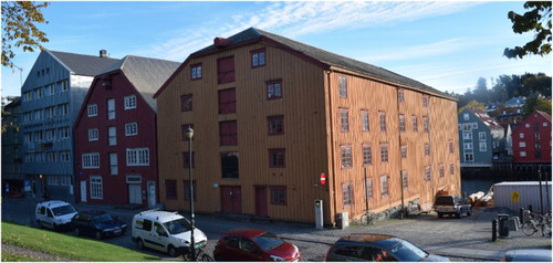
The building studied in this research, Kjøpmannsgata 27, is an old warehouse which was built during the first decade of the 18th century (). It survived a fire in 1935 and during the 1970s part of the building was demolished and rebuilt (Godal Citation2013). It is composed of five storeys, each approximately 500 m2, and a basement. Almost 80% of the structure was built on the riverbank and the remainder is supported by three rows of wooden columns directly inserted into the river. The pine building is composed of a column–beam structure with external log walls.
2 Kjøpmannsgata 27
Method
The purpose of this work was to carry out a qualitative investigation to identify the most decayed parts of Kjøpmannsgata 27 and to evaluate their condition (Cruz et al. Citation2013). Determining the extent and the state of decay is necessary in order to plan a rehabilitation scheme. The investigation consisted of archival research, a measured survey, visual inspection, moisture content measurements, impact sounding tests and, finally, drilling resistance measurements (Frontini, Siem and Nilsen Citation2015). Archival research was used to investigate the history of the structure and focussed on construction techniques and previous interventions. The results of the archival research were used to provide background information for the remainder of the study ().
3 Methodology
Measured survey and visual inspection
The measured survey and the visual inspection are the two main tools used to determine the locations of the structural elements and to identify the main areas of decay and deterioration. A measured survey was performed for each floor to obtain details of the plans and sections and all alterations and replacements were identified. It was found that the supporting structure of Kjøpmannsgata 27 is composed of a regular grid of columns.
All of the columns have a circular cross-section except those on the outer perimeter, which are square. The diameter of the circular columns ranges from 30 to 34 cm with spans between 2.7 and 3.9 m. In general, spans in the basement are shorter, with the shortest 0.8 m. The square columns have cross-sections ranging from 14 × 14 cm to 20 × 20 cm. The beams are all rectangular, with a 22 × 24 cm cross-section. The cross-sections of the joists vary (squared, rectangular and circular) with spans between 55 and 78 cm.
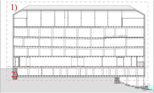
Following the methodology of Frontini, Siem and Nilsen (Citation2015), the subsequent visual inspection identified two main areas for investigation: the basement and the upper floors ().
4 Main areas of investigation
Moisture content
Accurate analysis using a hygrometer confirmed that the fibre saturation point had been exceeded in all of the foundation beams and columns in the basement (Frontini, Siem and Nilsen Citation2015). The part of the basement which is connected to the riverfront is permanently wet which has led to the development of plant life and possible fungal growth. Some of the supporting beams in this part of the building are on the verge of collapse. In the remainder of the basement, the structure is in direct contact with the ground and therefore all of the elements have a high moisture content in excess of 30%. As measurements of over 45% are not reliable, the moisture levels recorded in some areas were discounted and the areas were identified as ‘above the saturation point’. There are large variations in moisture level throughout the structure even within the same elements. Severe decay in some areas was obvious even from visual inspection.
On the upper floors, the timber elements are sound, and no efflorescence or wet areas were detected. The measured moisture content was below 23% in all of the timber members, and few elements were missing or had been removed, especially in the knee bracings. The part of the building with the most decay is therefore the basement, where the majority of the foundation beams are rotten (Riggio et al. Citation2014).
Drilling resistance device calibration
The zones that had been identified as possible areas of decay were tested using the micro-drilling technique. An IML PD-300F drilling resistance device was used (Singh Citation2000; Kasal and Anthony Citation2004; GmbH Citation2011). The drilling resistance device was first introduced as a tool to evaluate the condition of trees or historic timber structures by Rinn (Citation1992). The device measures the resistance as it drives a continuously rotating 1.5 mm needle into a timber element. The tip of the needle has a width of 3 mm. This ensures that all resistance is concentrated at the tip. The power consumption of the device is measured and converted to a value of drilling resistance.
The resistance measure RM is calculated as the ratio between the integral of the area under the recorded power consumption graph and the depth of needle penetration into the timber element, see Equation (1).
Although the use of the resistance measure to evaluate the mechanical properties of timber is questionable (Lear Citation2006), drilling resistance can be used to identify the main areas of decay and hidden voids inside timber members. It can also be used to detect and quantify deterioration. Resistance measurement can provide an accurate assessment of the level of decay, and can help ensure that any future repairs are carried out only on areas of rotten timber.
As pine is a soft wood, the IML PD-300F drilling resistance device was chosen because it has a high resolution and data are collected electronically based on a linear scale ordinate (y) axis. This enables the user to reliably distinguish between decay and sound-but-soft wood (Rinn Citation2013) which is an important consideration when working with soft wood as results can be misinterpreted easily. The in situ measurements were performed using a drilling needle with a diameter of 1.5–3.0 mm and a needle speed of 5000 rev min−1.
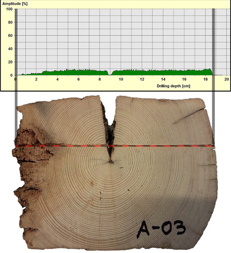
The device was first calibrated in the laboratory by performing approximately 50 measurements in eight different samples of timber from comparable 18th and 19th-century buildings. The samples used for calibration ranged in moisture content and condition. Prior to testing, each piece was cleaned and inspected to identify superficial defects and cracks. The pieces were then fixed to prevent any movement during testing and the moisture content was measured. The locations for testing were marked and identified with a code and then the drilling resistance measurements were performed. The final step was the analysis of the results which took into account both the average resistance and the amplitude of the oscillations in the data. After testing, the beams were cut to compare the cross-section with the results from the drilling resistance test as shown in .
5 Analysis of beam cross-section
The damage resulting from drilling resistance measurement is very limited, and if required, it is possible to perform a number of tests to identify the location and extent of areas of degradation with minimal loss of structural strength. The graphs recorded by the device corresponding to various types of decay have different characteristics; for instance, areas with total decay offer no resistance and the drilling resistance graph will appear as a flat line at zero (Rinn Citation1996; Kasal and Anthony Citation2004; Kasal and Tannert Citation2010).
Drilling resistance measurements
Prior to carrying out drilling resistance measurements, an initial assessment of the condition of the pillars and beams in the basement was performed using impact sounding. This is a common method for identifying decayed areas in timber elements. First, the beams and columns are carefully surveyed and examined along their entire length. The level of compactness is then ascertained by hitting the surfaces of the timbers with a hammer to determine which columns and foundation beams require further investigation.
For the present study, every column and foundation beam was identified on a grid (). Because of the differences in cross-section and condition of the timbers, the drilling test was carried out on all of the selected columns and foundation beams, and additional tests were performed on areas of potential decay identified by the impact sounding assessment and the visual inspection. The results of the drilling resistance measurements depend mainly on three factors: the species of wood, the condition of the wood (decay, cross-section loss and moisture content) and the direction of drilling (the angle of penetration of the needle).
6 Grid used for the identification of the elements. Basement plan
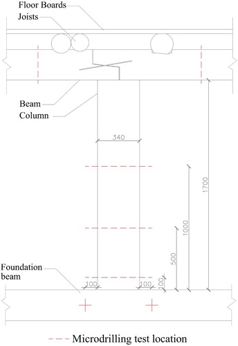
A minimum of three measurements were taken for each column and foundation beam. The columns were tested at 10, 50 and 100 cm above ground level with further investigations where necessary. The beams were tested close to the joints with the columns and in any additional areas identified during the visual inspection. shows the location of the points where measurements were taken.
7 Location of the drilling resistance measurement points
The main wooden elements were classified according to their condition based on the wood species and degree of decay obtained from the results of the visual inspection and the drilling resistance tests. The measured levels of decay were classified according to their extent from superficial decay to loss of cross-section.
Observations
Visual inspection was used to form the basis of this study. It was used to identify the areas for more thorough investigation and to determine the structural response of the individual members to obtain a preliminary idea of the load-bearing system. More details of the visual survey, the moisture content measurements and the impact sounding inspection can be found in Frontini, Siem and Nilsen (Citation2015). A table containing information regarding the results of the visual survey, the moisture content measurements and the drilling resistance measurements for each of the elements was created. An extract from this table is shown in .
Table 1 Extract from the table of observations of this investigation
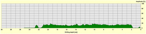
The results indicate that the wood within the columns and beams of the basement is in good condition and there is no evidence of decay or cross-section loss. None of the columns had exceeded their strength limit or displayed any signs of damage or decay. A typical graph from a drilling resistance test of a column is shown in ; it is clear that the resistance is normal and continuous throughout the cross-section. A small crack was detected close to the surface, but this was judged as insignificant with respect to the strength and stability of the element.
8 Drilling resistance graph for Column 0-B3

The main area of concern within the basement structure is the foundations. On the west side of the building, most of the foundation beams are missing and the columns are resting on the ground or on an unstable stone foundation. Beneath the columns there are stumps which show where the foundation beams were located in the original structure. On the east side of the building, the drilling test measurements show that some of the foundation beams have superficial decay or cross-section loss.
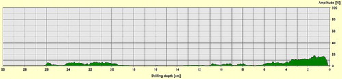
shows an example of a graph from a drilling resistance test of a foundation beam. In this particular beam, more than 40% of the cross-section shows low or no resistance at all and the area adjacent to one of the surfaces is also rotten.
9 Drilling resistance graph for foundation beam 0H4-0H5
Conclusions
It has been demonstrated in this paper that a drilling resistance device is an efficient and useful tool for evaluating damage and decay of a timber structure in order to form a basis to plan rehabilitation of the building. This was based on a study of a 19th-century warehouse located in Trondheim (Norway).
The results of the visual inspection and drilling resistance tests in this study show that the timber elements of the warehouse had a number of types of degradation: cracking, superficial and internal decay, and fungal growth due to the humid environment. The visual inspection formed the basis of the study and identified the main damaged zones for further investigation, which in this case were located in the basement. These areas were then examined using drilling resistance measurements to detect the above-mentioned defects. According to the tests, the condition of the columns and beams in the basement were good although they had a very high moisture content (see ). The foundation beams were in the worst condition and they affect the load-bearing capacity of the entire structure. The results of the drilling resistance tests were used to create a map of the undamaged members in the basement structure, see .
10 Map showing condition of the foundation beams
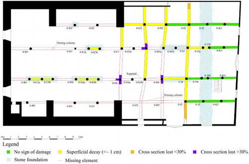
It is clear from this map that there is no sign of damage or superficial decay in the elements on the east side of the structure where the timber is in a more favourable environment with the potential for it to dry. In the central part of the basement, the beams have superficial decay or a small cross-section loss (<30%). Some of these beams are still weight-bearing even though they are in urgent need of repair. The beams on the west side of the building are in the worst condition and the results of the drilling resistance tests indicate that most of the surviving beams have high levels of cross-section loss. A high percentage of the original beams are missing in this area and as a result some columns are now resting on the ground (). This map highlights the elements which require replacement; the elements in green will be saved, while the others need to be replaced with new beams. It will also be necessary to design a membrane to separate the foundation beams from the ground to reduce moisture levels.
Table 2 Classification of foundation beams
A number of areas for future study have been planned. In the next stage, a detailed structural analysis will be carried out to develop the details of future repair works. The drilling resistance method will be used further to determine the effective cross-section of the elements (Lourenco et al. Citation2013). Furthermore, a study of the joints and their required repairs will be carried out. Finally, a plan for future monitoring and maintenance will be proposed.
Acknowledgement
The author gratefully acknowledges the valuable assistance of the Professor J.H. Siem.
References
- Bale, S. 2004. Non-destructive identification of defects in timber bridges. Road System and Engineering Technology Forum. Brisbane: The Bardon Centre, Department of Main Roads, Queensland Government.
- Branco, J. M., Piazza, M. and Cruz, P. J. S. 2010. Structural analysis of two king-post timber trusses: non-destructive evaluation and load-carrying tests. Construction and Building Materials. 24(3): 371–383. doi: 10.1016/j.conbuildmat.2009.08.025
- Cruz, H., et al. 2013. Guidelines for the on-site assessment of historic timber structures. International Journal of Architectural Heritage. accepted for publication.
- Frontini, F., Siem, J. and Nilsen, D. 2015. Assessment of an Historic Timber Structure using NDT: ‘Bryggene’ in Trondheim (Norway). Wrocáaw, Poland: DolnoĞląskie Wydawnictwo Edukacyjne (DWE), 491–503.
- GmbH, 2011. IML Instrumenta Mechanik Labor System. IML-Resi Manual and Warranty, Terms & Conditions. Wiesloch, Germany: Instrumenta Mechanik Labor System GmbH, Parkstraße.
- Godal, J.B. 2013. Kjøpmannsgata 27, enkel vurdering av tilstand og framlegg til tiltak før istandsetting til ny bruk.
- Kasal, B. and Anthony, R.W. 2004. Advances in situ evaluation of timber structures. Progress in Structural Engineering and Materials. 6: 94–103. doi:10.1002/pse.170.
- Kasal, B. and Tannert, T. 2010. In situ Assessment of Structural Timber. Ed. BOOKSERIES, RILEM. London: Springer Dordrecht.
- Lear, G.C. 2006. Improving the Assessment of In Situ Timber Members with the Use of Non-destructive and Semi-destructive Testing Techniques. MS Theses, NCSU libraries, North Carolina State University.
- Lourenco, P. B., et al. 2013. In situ measured cross section geometry of old timber structures and its influence on structural safety. Materials and Structures. 46: 1193–1208. doi: 10.1617/s11527-012-9964-5
- Riggio, M., et al. 2014. In situ assessment of structural timber using non-destructive techniques. Materials and Structures. 47(5): 749–66. doi: 10.1617/s11527-013-0093-6
- Rinn, F. 1992. Chancen und grenzen bei der untersuchung von konstruktionshoelzern mit der bohrwiderstandsmethode. Köln, Germany: Bauen mit Holz.
- Rinn, F. 1996. Resistographic visualization of tree-ring density variations. In: Tree Rings, Environment, and Humanity, Radiocarbon. Tucson: Department of Geosciences, University of Arizona, 871–878.
- Rinn, F. 2013. Practical application of micro-resistance drilling for timber inspection. Holztechnologie. 54(4): 32–38.
- Singh, J. 2000. The Resistograph and the Non-destructive Assessment of Timber Decay. Milton Keynes, UK: BCD Special Report Historic Churches.
- Solberg, H. and Suul, T. 1999. Arkitektur I 1000 År: En arkitekturguide for Trondheim. Trondheim: Trondhjems arkitektforening.